International Journal of Emerging Technology and Advanced Engineering
Website: www.ijetae.com (ISSN 2250-2459,ISO 9001:2008 Certified Journal, Volume 3, Issue 12, December 2013)
142
Design and Performance Analysis of DS-CDMA with Rake and
without Rake Receiver Communication System
Vaibhav Khairnar
1, Jitendra Mathur
2, Hema Singh
31
M. Tech. Scholar, 2Assistant Professor, 3Head, Assistant Professor, (Department of Electronics and Communication), RGPV University, Bhopal
Abstract—In this paper we have shown the performance analysis of DS-CDMA wireless communication system with and without Rake Receiver for multiple input using MATLAB simulator. It could satisfy the next generation requirement of multiple input environments. Here we use a simulator which simulates the multiple input waveform signals in the form of channels or fingers through wireless towards the Rake Receiver which will follow through the DS-CDMA technique due to its performance. As we know the CDMA is an excellent technique to analyze the cellular systems. The simulator will give the tremendous functional ideas about the different values of the design option. Here, the backbone of this system is a Matlab Simulator. As nowadays this becomes the iconic tradition to do the analysis. The effective method of system modeling is used to speed up the simulations. With the help of simulator we get the variations in the system parameters due to its different inputs. The transmitted data and the received data can be analyzed in the form of signal waveforms and channels. We can also analyze the input data with Rake and without Rake for different attenuation factor with Bit error rate.
Keywords— BER (Bit Error Rate), CDMA (Code Division Multiple Access), DS-CDMA (Direct Sequence CDMA), FDMA (Frequency Division Multiple Access), SNR (Signal to Noise Ratio), TDMA (Time Division Multiple Access).
I. INTRODUCTION
As Code Division Multiple Access (CDMA) is an application which is concerned with accommodating a number of simultaneous signal transmissions on the same channel, Code division multiplexing systems uses the spread spectrum technology and the Rake receiver concept to minimize communication errors resulting from multipath effects. In general, the number of multipath signals in the wireless channel is unknown and difficult to predict. The spread spectrum technology designs to spread the information signal over a wider bandwidth to make jamming and interception more difficult [1, 12].
A rake receiver allows each arriving multipath signals to be individually demodulated and then combined to produce a stronger and create an accurate signal.
The Rake receiver from the IS-95A CDMA system will use the three correlators and also a searcher, while the CDMA system TIA/EIA-95B limits the number of correlators in the Rake receiver to Six [4, 8].
The objective of this paper is to develop a Rake receiver through Matlab simulation that is able to increase the signal to noise ratio (SNR) performance with a minimum number of correlators.
CDMA is the popular application of DS spread spectrum techniques made it as DS-CDMA concept.
A. Frequency Division Multiple Access
In Frequency Division Multiple Access (FDMA), the available bandwidth is subdivided into a number of narrower band channels. Each user from the channel is allocated a unique frequency band where transmit and receive is on. During a same call no any other user can use the same frequency band.
[image:1.612.370.517.550.625.2]Each user is assigned a forward link channel (from the base station to the mobile phone) and also a reverse channel (revert back to the base station); each is being a single way link. The transmitted signal of each channel is all the way continuous uses analog transmissions. The bandwidth of FDMA channel is generally low (30 kHz) as each channel only supports only one user. FDMA is used as the primary breakup of large allocated frequency bands and is used as part of most multi-channel systems [6].
Fig 1: Frequency Band Channel [2]
B. Time Division Multiple Access
International Journal of Emerging Technology and Advanced Engineering
Website: www.ijetae.com (ISSN 2250-2459,ISO 9001:2008 Certified Journal, Volume 3, Issue 12, December 2013)
143
[image:2.612.53.280.228.290.2]Fig. 2 shows how the time slots are provided to users in a round robin fashion, with this each user being assigned one time slot per frame. TDMA system also transmit the data in a buffer and burst method, hence the transmission of each channel is non-continuous and will provide the accurate mode of signal to be propagated by considering its signal to noise ratio[6].
Fig 2: TDMA Scheme [1]
C. Code Division Multiple Access
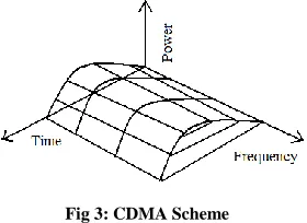
Code Division Multiple Access (CDMA) is a spread spectrum technique that uses neither frequency channels nor time slots. In CDMA, the narrow band message is multiplied by a larger bandwidth signal, which is a pseudo random noise code. All users in a CDMA system uses the same frequency band and transmit it very simultaneously. The transmitted signal is then recovered by correlating the received signal with the PN code used by the transmitter [1, 12].
In the demodulation of each type of PN signal, the signals from the other side users of the channel appear as an additive interference. A major advantage of CDMA is that a large number of users can be accommodated if each transmits messages for a short period of time [12].
[image:2.612.331.557.301.410.2]Some useful properties that have made CDMA stronger are: Signal hiding and non-interference with existing systems, Anti-jam and interference rejection, Information security, Accurate Ranging, Multiple User Access, Multipath tolerance.
Fig 3: CDMA Scheme
The data to be transmitted (a) is spread before transmission by modulating the data using a PN code. This broadens the spectrum as shown in (b).
In this example the process gain is 100 as the spread spectrum bandwidth is 125 times greater the data bandwidth. Part (c) shows the actual received signal. This may consists of the required signal with background noise and interference from any other CDMA users or radio sources.
The received signal is recovered by multiplying the signal by original spreading code. Also this process may cause the wanted effective received signal to be dispread back to the original effective transmitted data. When all the other signals are uncorrelated with the PN spreading code, they become more spread. The wanted signal in (d) is then filtered removing the wide spread interference and noise signal, it is shown in the Fig.4 below
Fig. 4: Basic CDMA Generation [2]
D. Direct Sequence Spread Spectrum
The spread spectrum modulation techniques are originally developed for use in the military and intelligence communications systems due to their resistance against jamming signals and low probability of interception (LPI). They are immune to various kinds of noise and multipath distortion.
[image:2.612.101.241.542.644.2]International Journal of Emerging Technology and Advanced Engineering
Website: www.ijetae.com (ISSN 2250-2459,ISO 9001:2008 Certified Journal, Volume 3, Issue 12, December 2013)
[image:3.612.344.537.143.219.2]144
Fig.5: Basic model of DS-SS Communication System [12]
II. RAKE RECEIVER
[image:3.612.52.285.150.276.2]Rake receiver architecture allows an optimal combining of energy received over path with different signal waveforms. It avoids the wave cancellation (fade) if delayed path arrive with phase differences and weighs signals coming in with different Signal to noise ratios. It also reduces the bit error rate and bit transmission rate. The basic components and the models of channel for the Rake Receivers are as mentioned in Fig. 6[12].
Fig. 6: Rake Receiver Process [12]
In the matched filter receiver, the signal is being correlated with a locally generated signal waveform. However, the signal is distorted by the channel; the receiver should be correlate the incoming signal by an expected received signal, rather than by transmitted waveform. Hence the receiver should estimate the delay profile of the channel, and adapt its locally generated copy according to this estimate signal [4, 8].
[image:3.612.330.557.412.565.2]In the multipath channel, delayed reflections, noise, signal waveforms interfere with the direct signal. Whereas a DS-CDMA signals suffering from multipath dispersion can detect a Rake receiver. This receiver extremely combines signals received by multiple paths.
Fig. 7: Matched Filter Receiver for AWGN Channel [1]
III. MULTIPATH FADING CHANEL
The communication channel is the medium which the transmitting radio signal goes through in order to reach the receiver. The channel can be modeled as a linear filter with a time varying channel impulse response. A channel impulse response describes the amplitude and phase effects that the channel will impose on the transmitting radio signal, as it transmits through the medium.IS-95 CDMA Communication channels are often modeled as a multi path fading channel, as it is the best Modeling for a mobile communication channel.
For the different transmitter how the Rake Receiver works to receive the date is shown in the below Fig. 8.
Fig.8: Rake Receiver with 5 channels [1]
[image:3.612.49.284.426.487.2]International Journal of Emerging Technology and Advanced Engineering
Website: www.ijetae.com (ISSN 2250-2459,ISO 9001:2008 Certified Journal, Volume 3, Issue 12, December 2013)
145
IV. MULTIPATH RECEPTION
In a multipath reception, delayed channel reflections interference with direct signal only. Though, a DS-CDMA signal is coming from multipath dispersion is then detected by a rake receiver. This rake receiver can combines all the signals received over multiple Path.
In designing of a RAKE receiver, it is ideal to have as many fingers as possible. Each finger picks a different delayed signal and therefore all fingers of a RAKE receiver contains, the higher costs associated with its manufacture and operation.
The main advantage of CDMA is the capability and capacity of the signals that arrive in the receivers with different time delays. This technique is called multipath.
[image:4.612.64.262.377.523.2]FDMA and TDMA, which are narrow band systems, cannot do have the finger concept for the multipath arrivals, and results to equalization which is the negative effects of multipath .Due to its wide bandwidth and rake receivers, CDMA uses the multipath signals and also combines them to make an stronger signal at the receivers.
Fig. 9: Bit Error in Multipath Fading [1, 7]
V. SYSTEM MODEL ANALYSIS
The rake receiver gathers the energy received over all the different delayed propagation paths. As per the maximum ratio combining principle, the SNR at the output is nothing but the sum of the SNRs in the separate branches, provided that,
1. We assume that only AWGN is present (no interference) 2. Codes with a time offset are truly orthogonal.
Signals are arriving with the same excess propagation delay as the time offset in the receiver are retrieved exactly, because
This reception concept is repeated for every delayed path that is received with accurate power. According to single correlator branch, multipath self-interference from any other paths is attenuated here, because one can choose codes such that [1, 11].
VI. PURPOSE OF SIMULATOR
The objective of this research is to simulate and evaluate the performance of deferent parameter and RAKE receiver performance for the CDMA. It is well known that CDMA simulator and the simulation software developed for this research implements RAKE and without RAKE methods in combination with CDMA standard.
This work will provide crucial information leading to the implementation of CDMA simulator in a real-world system. RAKE to multiple stages of interference cancellation. RAKE was used in this work along with receivers that used the information in the channel. For both rake and without rake, we compare them in multipath environment. It will be shown that the use of number of bit error in received data by the RAKE receiver is less than the received data of without RAKE receiver advantages of RAKE receivers [4, 10].
VII. SIMULATION ANALYSIS
International Journal of Emerging Technology and Advanced Engineering
Website: www.ijetae.com (ISSN 2250-2459,ISO 9001:2008 Certified Journal, Volume 3, Issue 12, December 2013)
146 A. Command Window for simulation of CDMA with Rake
receiver
[image:5.612.323.569.126.320.2]When we run the w_rake.m then this will open this command window. This simulation shows the information about the no. of user, no. of finger, 15 bit transmitted bit data and 15 bit received bit data. In simulation with rake, it shows the user data and received data which is 15 bit in the form of having 15 columns.
Fig. 10: Command Window for simulation of CDMA with Rake receiver
B. Command Window for simulation of CDMA without Rake receiver
[image:5.612.48.289.236.424.2]When we run the wo_rake.m then this will open this command window. The simulation will perform on this command window, this also shows the information about the no. of user, 15 bit transmitted bit data and 15 bit received bit data. In simulation with rake, it shows the user data and received data which is 15 bit in the form of having 15 columns. The user has to put information about the no. of user only (no need to add finger) to simulate and after simulation we will get figure of transmitted data and received data which has same users bits at both the sides.
Fig. 11: Command Window for simulation of CDMA without Rake receiver
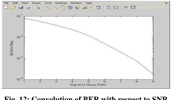
C. Convolution of Bit Error Rate with respect to Signal to Noise Ratio
When we run the BER.m then this will open this figure window. The simulation will perform on this command window base on the input provided in built. As the bit error rate is decreased, the signal to noise ratio will increase accordingly.
Fig. 12: Convolution of BER with respect to SNR
D. The above Fig. 2 illustrates an GUI for simulation of CDMA
When we run the rake.m then this will open this GUI, This simulation will perform on GUI shows the information about the no of user, user to simulate, no. of bit error rate and attenuation factor and after simulation we
will get figure of transmit data and received data,it shows
[image:5.612.356.532.440.542.2]International Journal of Emerging Technology and Advanced Engineering
Website: www.ijetae.com (ISSN 2250-2459,ISO 9001:2008 Certified Journal, Volume 3, Issue 12, December 2013)
[image:6.612.318.572.108.310.2]147
Fig. 13: GUI for simulation of CDMA
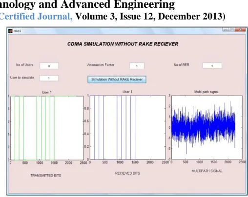
E. GUI for CDMA simulation without RAKE when attenuation factor is 1
When we run the rake1.m then this will open this GUI, This simulation will perform on GUI shows the information about the no of user, user to simulate, no. of bit error rate and attenuation factor. After the simulations we will get figure of transmit data bits and received data bits, number of bit error in received data for without RAKE
receiver, this result show the comparison between
simulation with and without RAKE receiver in CDMA. When we push the push button simulation without RAKE Receiver button with attenuation factor 1 then the transmitting data and receiving data, no of bit error, the attenuation factor is one in this condition bit error is zero this shows that the power level of transmitting data is high then the bit error in receiving data is less.
As we increase the attenuation factor the bit error rate will decreases, it shows that as we attenuate the signal frequently, we would get the efficient output at the receiver.
When we push the push button simulation without RAKE Receiver when attenuation factor is 1 then the multipath receiving signal will be multipath data as shown in third session.
Fig. 14: GUI for CDMA simulation without RAKE when attenuation factor is 1
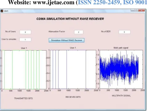
F. GUI for CDMA simulation without RAKE when attenuation factor is 2
When we run the rake1.m then this will open this GUI, This simulation will perform on GUI shows the information about the no of user, user to simulate, no. of bit error rate and attenuation factor. After the simulations we will get figure of transmit data bits and received data bits, number of bit error in received data for without RAKE
receiver, this result show the comparison between
simulation with and without RAKE receiver in CDMA. When we push the push button simulation without RAKE Receiver button with attenuation factor 2 then the transmitting data and receiving data, no of bit error, the attenuation factor is one in this condition bit error is zero this shows that the power level of transmitting data is high then the bit error in receiving data is less.
As we increase the attenuation factor the bit error rate will decreases, it shows that as we attenuate the signal frequently, we would get the efficient output at the receiver.
[image:6.612.50.291.127.338.2]International Journal of Emerging Technology and Advanced Engineering
Website: www.ijetae.com (ISSN 2250-2459,ISO 9001:2008 Certified Journal, Volume 3, Issue 12, December 2013)
[image:7.612.318.567.111.303.2]148
Fig. 15: GUI for CDMA simulation without RAKE when attenuation factor is 2
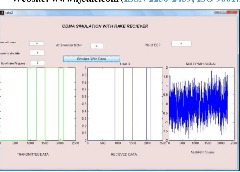
G. GUI for CDMA simulation with RAKE when attenuation factor is 1
When we run the rake2.m then this will open this GUI, This simulation will perform on GUI shows the information about the no. of user, user to simulate, no. of rake fingers, no. of bit error rate and attenuation factor. After the simulations we will get figure of transmitted data
bits and received data bits, number of bit error in received
data for with RAKE receiver, this result show the
comparison between simulation with and without RAKE receiver in CDMA.
When we push the push button simulation with RAKE Receiver button with attenuation factor 1 then the transmitting data and receiving data, no of bit error, the attenuation factor is one in this condition bit error is zero this shows that the power level of transmitting data is high then the bit error in receiving data is less.
As we increase the attenuation factor the bit error rate will decreases, it shows that as we attenuate the signal frequently, we would get the efficient output at the receiver.
When we push the push button simulation with RAKE Receiver when attenuation factor is 1 then the multipath receiving signal will be multipath data as shown in third session.
Fig. 16: GUI for CDMA simulation with RAKE when attenuation factor is 1
H. GUI for CDMA simulation with RAKE when attenuation factor is 2
When we run the rake2.m then this will open this GUI, This simulation will perform on GUI shows the information about the no. of user, user to simulate, no. of rake fingers, no. of bit error rate and attenuation factor. After the simulations we will get figure of transmitted data
bits and received data bits,number of bit error in received
data for with RAKE receiver, this result show the
comparison between simulation with and without RAKE receiver in CDMA.
When we push the push button simulation with RAKE Receiver button with attenuation factor 2 then the transmitting data and receiving data, no of bit error, the attenuation factor is one in this condition bit error is zero this shows that the power level of transmitting data is high then the bit error in receiving data is less.
As we increase the attenuation factor the bit error rate will decreases, it shows that as we attenuate the signal frequently, we would get the efficient output at the receiver.
[image:7.612.50.289.121.301.2]International Journal of Emerging Technology and Advanced Engineering
Website: www.ijetae.com (ISSN 2250-2459,ISO 9001:2008 Certified Journal, Volume 3, Issue 12, December 2013)
[image:8.612.51.294.126.300.2]149
Fig. 17: GUI for CDMA simulation with RAKE when attenuation factor is 2
VIII. FUTURE SCOPE
We have developed a simulator made in our paper work, we have shown in this paper that how rake receiver in used for CDMA to decrease bit error due to multiple input interferences and also it can simulate with the different attenuation factor. It can simulate a CDMA encoding and decoding process, here the data is assumed to be travelled through multiple path and the effect of multiple path and CDMA is assumed to generate the multipath effect and the data is pass through the different path and assumed at receiver end just before the decoder to avoid the multipath effect RAKE receiver is used the RAKE receiver concept is introduced in the decoding process.
In future, we can add more factors to implement this system to get effective received signal like symbol error rate, equalizer parameters and Relayed fading channel parameters, etc.
IX. CONCLUSION
The system which can be efficiently reduce the bit error rate is introduced in this paper i.e. DS-CDMA technique. It is also putting the impact on the wireless system that how we increase or decrease the attenuation factor and hoe it affect on the wireless system while applying the multiple inputs.
Acknowledgement
The authors like to express their sincere thanks to the Electronics and Communication Department of TIT (Excellence), RGPV University, Bhopal for their contribution and continuous support and encouragement during this Project and Paper work.
REFERENCES
[1] Vaibhav Khairnar, Jitendra Mathur and Hema Singh, “Multiple Input Analysis of DS-CDMA Rake Receiver Simulator”, in International Journal of Engineering Research and Applications, ISSN:2248-9622, Vol.3, Issue 6, pp. 788-792, Nov-Dec 2013.
[2] M. F. Hashmi, Pradip Dhakad and Baluram Nagaria. “Design and Analysis of DS-CDMA Rake Receiver Simulator for Wireless Communication,”, in IEEE Vol. 978-1-4244-9190-2/11, IEEE publications, 2011.
[3] N. Anand Ratnesh, K. Balaji, J. V. Suresh, L. Yogesh and B. Anil Babu, “Performance Analysis of DS-CDMA Rake Receiver over AWGN channel for Wireless Communications” in International Journal of Modern Engineering Research, Vol. 2, Issue 3, pp. 859-863, May-June 2012.
[4] Leila Gazzah, Hatem Boujemaa and Mohamed Siala, “Discrete time Rake receiver for cooperative DS-CDMA systems”, IEEE publications, 2011.
[5] K. Murali.Krishna, Abhijit Mitra and Cemal Ardil, “A Simplified Single Correlator Rake, Receiver for DMA Communications” International Journal of Information Technology Volume 2, Number 4, 2005
[6] P. Jung, P. W. Baier, and A. Steil, “Advantages of CDMA and Spread Spectrum Over FDMA and TDMA in Cellular Mobile Radio Applications,” IEEE Transactions Vehicular Technology, Vol. 42, no. 3, pp. 357- 364, August
[7] J. C. Liberti and T. S. Rappaport, “Analytical Results for Capacity Improvements in CDMA,” IEEE Transactions on Vehicular Technology, Vol.43, No. 3, pp. 680-690, August 1994.
[8] Thierry clessienne, “A general expression of Rake receiver performance in DS-CDMA downlink”, IEEE publications, 2007. [9] W. C. Y Lee, “Overview of cellular CDMA”, IEEE Trans. on
Vehicular Technology, Vol. 40. No.2. pp.291-302, May 1991 [10] R. Lupus and S. Verdi, “Linear Multiuser Detectors for Synchronous
Code Division-Multiple-Access Channels,” IEEE Trans. Info. Theory, vol. 35, no.1, pp. 123-136, Jan. 1989.
[11] R. A. Cameron and B. D. Werner, “An Analysis of CDMA with Imperfect Power Control”, Proceedings of 42nd IEEE Vehicular Technology Conference, Denver, CO, pp. 977-980, 1992.
[12] John G. Proakis and Masoud Salehi, “Digital communications”, McGraw-Hill, New York, 2008, 5th Edition.
[13] Esmael H. Dinan and Bijan jabbari “Spreading codes for Direct sequence CDMA and wideband CDMA cellular Networks” IEEE communications magazine, Sep 1998.
![Fig 1: Frequency Band Channel [2]](https://thumb-us.123doks.com/thumbv2/123dok_us/8721482.884305/1.612.370.517.550.625/fig-frequency-band-channel.webp)
![Fig. 7: Matched Filter Receiver for AWGN Channel [1]](https://thumb-us.123doks.com/thumbv2/123dok_us/8721482.884305/3.612.330.557.412.565/fig-matched-filter-receiver-awgn-channel.webp)
![Fig. 9: Bit Error in Multipath Fading [1, 7]](https://thumb-us.123doks.com/thumbv2/123dok_us/8721482.884305/4.612.64.262.377.523/fig-bit-error-multipath-fading.webp)