Evaluation of Pressure changes for Capillary
and Fishbone valves In Lab-on-CD systems
Peyman J.1, student member IEEE, A. Akbar Nozari2, N. Soin1, member IEEE, F. Ibrahim3, member IEEE 1 Dept. of Electrical Engineering, Faculty of Engineering, University of Malaya, 50603 Kuala Lumpur 2 Dept. of Mechanical Engineering, Faculty of Engineering, University of Malaya, 50603 Kuala Lumpur 3 Dept. of Biomedical Engineering, Faculty of Engineering, University of Malaya, 50603 Kuala LumpurEmail: [email protected]
Abstract-This paper describes an investigation in Capillary and Fishbone valves as controlling medium of liquid flow for micro-devices and diagnosis methods like Enzymed Linked Immonusorbent Assays (ELISA). Numerical simulation by MATLAB programming was employed to predict the pressure gradient at the Capillary valve expansion part and Fishbone valve section. The analysis results of pressure gradient versus channel width values depicted that an increase in the width of channel leads to a decrease in the pressure gradient. While an increase in Surface tension raises up the required pressure gradient for both valves. Pressure gradient sensitivity to contact angle between liquid and gas in the Capillary valve is more than the Fishbone valve.
I. INTRODUCTION
The novel systems and devices in various fields of life and research from natural and biological science to industrial and technological field are totally concerned with Microsystems. Improvement of machine’s friendliness, Reduction in energy consumption, size and weight of system, increase the accuracy and reliability of result, minimization of process time and cast caused accelerated growth in micro scale apparatus [1, 2]. Special attention has been given to Micro-system in Biomedical subjects and diagnosis of diseases because it consumes very slight volume of sample like antibody, subtract and enzyme. Lab-On-a-CD, Lab-On-a-Chip (LOC), Biochip and BioMEMS are prominent units in this area [3, 4]. Application of centrifugally driven assay unit comprises High-Throughput Screening (HTS), CD platform for Enzymed Linked Immonusorbent Assays (ELISA), Multiple parallel assays, Cellular Based assays On CD platform, Automated Cell Lysis on a CD, Integrated Nucleic Acid Sample Preparation and PCR amplification [4]. All of mentioned devices and methods have some common fundamental law, and they employed similar equations and parts. Amongst micro pumps, micro channel and micro valve as three main parts of Microsystems [5], the latter has specific importance and complexity which it uses to control the fluid flow inside the micro channel. Invention of variety of controlling trends e.g. thermally actuated gels, magnetically actuated ferrofluid,
pneumatically controlled membranes generally active valves which need motivation or moving parts and on the other side Capillary valve, polymer check valves, elastomer valves and hydrophobic valves in general manner passive valves that do not require animating pieces [1, 6, 7], illustrates how different condition and application direct the researchers and engineers to new designs. Valve could be divided into three major categories based on the motivation of the flow: mechanical, electrical and thermal valves [8]. Considering the passive valves, Capillary valve widely utilized in microfluidic flow system as a pressure barrier to halt the fluid. It works based on surface tension between liquid and gas and performance of this one direction valve depend on geometry of channel [5]. The Capillary valve can be divided into 2 types; hydrophobic patch Capillary valve and sudden expansion Capillary valve [9]. Although Capillary valve benefit from advantages of possibility of rapid prototyping, easily integration, and continuity in subtract material flow, it suffers from three main drawbacks; difficulty for reconfiguring, dependency on fabrication process variances and capability of being used for a limited range of fluidic medium and fluid are principal disadvantages of Capillary valve [10].
Material which is employed for the micro-channel fabrication is customarily single crystal silicon [9] or mostly hydrophobic polymers for instance polymethylmethacrylate (PMMA) from thermoplastic polymers and polydimethylsiloxane (PDMS) from Elastomeric polymers [10]. Not only the fluid property affect the system parameters, but also Hydrophobicity of micro-channel surface is a prominent feature that it determines the contact angle of meniscus with a wall. Generally it was observed that the liquid advanced in the channel with hydrophobic wall much slower than corresponding hydrophilic condition [1], so, preference is given to hydrophobic surface for this microfluidic flow application. The passing fluid in the micro-channel could influence hydrophobicity of channel and consequently contact angle. Protein, inevitable material in ELISA process for occupying the vacant space between antibodies or antigens on the wall, is prone to bind to the wall so it causes the contact angle between the fluid and the wall decreases.
hydrophobicity. In spite of that the fluorine-plasma treatment method on the surface is the most prevailing approach for making the superhydrophobic surface, the Fishbone sketch was based on repetitive geometrical changes in cross section of the channel. In this manner it can be fabricated and integrated to the system comfortably and similarly Capillary valve fabrication and integration to the main part [6].
Capillary valve could be shaped in different frames, and all the results of pressure changes for Capillary valve associated to circular, rectangular and trapezoidal cross section of channel revealed as in [9]. This paper presents the evaluation and analysis between the Capillary and Fishbone valves in controlling the liquid flow for micro-devices.
II. THEORETICAL ANALYSIS
A. ELISA method
Enzyme-linked immunosorbent assay (ELISA) employs as a powerful approach in survey for chemical, biological, clinical, environmental and industrial applications. Recently, novel designed and fabricated CD of centrifugal microfluidic platform for ELISA superseded by a 96-well microtiter plate. ELISA should comprise fundamental stages to incubate essential components on the wall and on the sublayer components. After that a defined mark illustrates the result in detection segment. The surface of detection segment is host of antibodies at the first step to be incubated on it. After unbounded antibodies are washed away from the detection chamber, blocking proteins enter there to occupy vacant places among the antibodies.
This strategy leads to efficient binding of antigens to antibodies instead of chamber surface. When the surplus proteins are washed away, Antigen incubation is executed and unrestrained antigens are conveyed to the waste reservoir. The secondary antibody (conjugate) incubation succeeds the enzyme substrates for adding to the previous chains. The detectable signal e.g. fluorescence or different colors can be seen when the enzyme substrates react with conjugates [4]. The intensity of radiated fluorescence strongly depends on utilized solution e.g. De-ionized water (DI water) or Tris Assay Buffer (TAB) and it changes by time up to the point which the slope of figure tends to zero [11].
The Capillary valve is widely used in ELISA systems to control the sequence of the materials injection to the detection chamber. The rotation frequency determines which reservoir should release its liquid into the channel. From the mechanical aspect, the fluid flows in the channel when the pressure gradient behind the liquid from centrifugal force overcomes the pressure gradient originated from surface tension between liquid and gas.
Figure 1.The general principle and procedures of ELISA [7].
B. Theory of Capillary valve
Capillary valve is considered as a passive valve which it defines as abrupt expansion in the micro-channel in this study and the pertaining equation would be given as follow. Relation of pressure gradient between the inside and outside of the fluid in the channel called Young-Laplace equation is a primary statement in the Capillary valve and its value governs the fluid flow and stagnation. The pressure gradient can be determined by Surface tension γ, and the contact angle θ. As a matter of fact, the different between pressure in inlet and outlet equals to total surface tension component along with the length of micro-channel divided to cross section area of channel. Equation (1) denotes pressure gradients for the circular cross section channel [5].
D s
P =−4γsinθ
Δ (1)
where D is diameter of round tube. Differentiation of total interfacial energy Ut with respect to injected liquid volume Vl assesses Pressure gradient for rectangular channel [12].
(2)
where θv is the liquid contact angle with the top or bottom walls, θs is the contact angle of side wall and w stands for the width of channel as well as h for its height [8].
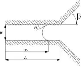
[image:2.612.317.565.76.152.2]This study, concentrated in disk-like micro-fluidic platform. Figure 2 shows the schematic configuration of the Capillary valve where β is the expansion angle of the valve [12]. Figure 3 depicts the sketch of Fishbone valve [13].
Figure 2. Schematic configuration and parameters defined for the meniscus developed in a rectangular Capillary channel [12]
⎟
⎠
⎞
⎜
⎝
⎛
+ −
= Δ
h v w
s s
[image:2.612.362.500.573.687.2]Figure 3. Schematic configuration and parameters defined for the meniscus developed in a rectangular Fishbone channel [13]
Centrifugal force inspires the fluid in the micro-channel on a rotating disk, depends on the frequency of rotation and distance of beginning and ending point of liquid from the center of the disk. Therefore, the pressure gradient indicated in (3) depends on rotating frequency [11].
(
)
⎟
⎠
⎞
⎜
⎝
⎛
+− =
Δ
2 2 1 1 2
2 r r r r
c
P ρω (3)
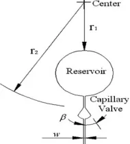
where r1 and r2 are the radius from the center of CD to the beginning of the reservoir and to the beginning of the Capillary valve, respectively(Figure 4).
C. Fishbone valve
Preventive force originated from surface tension is very sensitive to contact angle. The fluid in the channel is capable of changing the surface property and consequently the contact angle. The blocking protein in the ELISA strongly affects on the surface of the wall and reduces the contact angle through making the surface more hydrophilic. Fishbone valve is an alternative technology to overcome this problem. In fact, Fishbone valve is series of Capillary valves follow each other in sequence. Figure 3 shows that the Fishbone has width of wb, Fishbone distance of d along the length of channel and n as the number of them. Effect of Fishbone valve parameters appears in rotational speed (ω) as mentioned in [13].
[image:3.612.319.566.531.680.2]Fishbone formula completely complies with the Capillary valve equation. Equality of the centrifugal force and the surface tension assess the rotating speed of the motor when the liquid release in the channel. The frontier surface of the fluid is called meniscus. Burst frequency is the rotating speed in which the meniscus starts to move. The Fishbone burst frequency can be represented in terms of the valve parameters [13].
Figure 4. Schematic of micro-fluidics fabricated on a rotating disk equipped with a Capillary valve to regulate the centrifugal-driven flow. A straight micro-channel links the reservoir and the Capillary valve [12]
III. NUMERICAL SIMULATION
The study has developed a programming code with MATLAB according to the Fishbone and Capillary valves input variables specifications. The channel width and height are between 50 µm to 150 µm, while the radius of r1 and r2 are 25000 µm and 30000 µm, respectively. The density of the fluid (
ρ
) is 1 g/cm3 and the surface tension (σ) is from 10(N*103)/m to 90(N*103)/m. The Fishbone wf and d are 100 µm and it has five Fishbones in a valve (see Figure 3). The kinetic model was used in numerical simulation to obtain the side-view contact angle on top and bottom of the channel [13]. When considering these input variables, the study has developed the output performance in terms of the pressures between r1and r2 (ΔP) versus the width of channel (wc) and the surface tension (σ).The capillary valve just opens one time when the Fishbone valve opens number of times in different sections. For a specific place on a platform with the same geometry, the pressure in Capillary valve section was compared with the pressure in last Fishbone.
IV. RESULTS AND DISCUSSIONS
The preliminary result of the MATLAB program was compared with the empirical result conducted by Alain Gliere [9] for the validation the accuracy of the program. The numerical simulation results obtained in this study are in agreement with Alain Gliere.
Theoretically different contact angle will have an effect in the pressure gradient. Thus, in this study two contact angles of 60o and 90o were used to analyze the pressure gradient for the Fishbone and Capillary valve [5]. Fluid in this study is Water with density of 1 kg/m3 and surface tension of 72.9 mN/m.
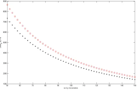
The pressure gradient in the Fishbone and Capillary valves
[image:3.612.113.208.581.686.2]versus different values of the channel width are shown in Figure 5. In Figure 5 the point constitutes upper line refers to the Capillary valve and the lower line consists of points for the Fishbone valve results. The Figure 5 depicts that the pressure for Capillary valve is more than Fishbone valve for each specific width of the channel.
Both valves had the decreasing rate of changes when the width of channel increased. The Fishbone valve employed for applications that the surface hydrophobicity of micro-channel or Capillary valve changes to more hydrophilic state, so the fluid could flow in the channel with less pressure gradient. The Fishbone valve can determine the burst time, therefore it regulates the releasing time from reservoir for the liquid with proteins which alters the surface characteristic and contact angle.
Figure 6 illustrates the pressure changes in terms of width of micro-channel for 90o as the contact angle. Drastic effect of contact angle can be seen for the channel with smaller width. Comparison of the curves for Fishbone and Capillary valves by different contact angles 60o and 90o showed the Capillary valve is more sensitive to contact angle changes than Fishbone valve. This is the advantage of fishbone for using in micro-channel which it carries the protein contained liquid. The difference of pressure gradient between Capillary and Fishbone valves is noticeable for micro-channels with smaller width and it reduces as the channel width increases. So, for smaller micro-channel carries the proteins, pressure gradient of the Fishbone valve could not be replaced with corresponding value from Capillary valve carve, but whenever the width of channel were enlarged the substitution does not have great effect in pressure gradient. Operating liquid in ELISA contains antibodies, antigens, proteins and enzymes
[image:4.612.318.554.301.457.2]that they changed the physiochemical properties of pure water.
Figure 6. Pressure gradient vs. channel width. Comparison of simulated results for Capillary valve (□) and Fishbone valve (*) by contact angle 90o.
Since there was no study on the comparison between the Capillary and Fishbone valves, the only way conducts the analysis is to do practical experiment.
Figure 7 discloses how pressure gradient changes for range of surface tension from 10 to 90 mN/m in Capillary and Fishbone valves. The pressure gradient of Capillary and Fishbone valves are very close to each other for small quantity of surface tension i.e. in 10 mN/m, and they were enlarged linearly for the larger surface tension meanwhile differences between them increase, eventually at surface tension of 90 mN/m it became maximum.
Figure 7 also shows the result for both Capillary and Fishbone valves with contact angle of 60o when the width of channel is constant and equal to 10 µm. Figure 7 could be useful to know the range of pressure gradient for each specific surface tension.
[image:4.612.37.279.500.658.2]Figure 8 depicts the pressure gradient versus surface tension for contact angle of 90o. The rate of changes did not
Figure 7. Pressure gradient vs. surface tension. Comparison of simulated results for Capillary valve (□) and Fishbone valve (*) by contact angle 60o.
Figure 8. Pressure gradient vs. surface tension. Comparison of simulated results for Capillary valve (□) and Fishbone valve (*) by contact angle 90o.
[image:4.612.319.559.500.658.2]oscillate for 60o and 90o, but higher pressure gradient is required for θ = 90o, moreover this value for Capillary valve isgreater than Fishbone valve for the same surface tension.
V. SUMMARY
Capillary valve commonly employs in micro-fluidic devices is low cost, high accuracy, easy fabrication, commercially available in a wide range of material and readily manipulation. Biomedical and diagnostic assay like ELISA require reliable controlling mechanics. The Capillary valve regulates the fluid flow in its micro-channels. Proteins binding to the surface of channel and chamber changes the contact angle. Fishbone valve application is suitable for protein containing systems. Centrifugal force drives the fluid out of the reservoir whereas the surface tension intends prevent this motion. Numerical simulation reveals how the pressure gradient changes with width of channel for Capillary and Fishbone valves. Less pressure is required for Fishbone valve rather than Capillary valve in the same condition. In other analysis, the effect of contact angle was illustrated for 90o and 60o in different width and surface tension. The pressure linear changes in terms of surface tension, showed that for the same surface tension and width, Capillary valve required greater pressure gradient than Fishbone valve. Contact angle, surface tension and width of channel could completely change the pressure gradient in Fishbone valve as well as Capillary. The result of this study can used to determine which valves are appropriate for the case of which contains protein in a specific limited geometry of space or area only.
Acknowledgment
This research is supported by University Malaya Research Grant, Project No. : RG023/09AET.
REFERENCES
[1] Critical pressure for Capillary valves in a Lab-On-a-Disk: CFD and flow visualization, Goncalo Silva, Nuno Leal, Viriato Semiao, 2009.
[2] Integrated sample preparation, Reaction and Detection on a High-frequency Centrifugal Microfluidic Platform, J. Steigert, M. Grumann, T. Brenner, K. Mittenbuhler, T. Nann, J. Ruhe, I. Moser, S. Haeberle, L. Riegger, J. Riegler, W. Bessler, R. Zengerle, and J. Ducree, October 2005.
[3] Fundamental of microfabrication, Centrifuge Based Fluidic Platforms, Jim V. Zoval and M. J. Madou,
[4] Design and testing of a microfluidic biochip for cytokine enzyme-linked immunosorbent assay, Hongyan He, Yuan Yuan, Weixiong Wang, Nan-Rong Chiou, Arthur J.Epstein, and l James Lee, 2009.
[5] How the Capillary burst microvalve works, Hansang Cho, Ho-Young Kim, Ji Yoon Kang, Tae Song Kim, 2006.
[6] New valve and bonding designs for microfluidic biochips containing proteins, Chunmeng Lu, Yuing Xie, Yong Yang, Mar M. C. Cheng, Chee Guan koh, Yunling Bai and James Lee, Yi Je Juang, 2007.
[7] Passive flow switching valves on a centrifugal microfluidic platform, Jitae Kim, Horacio Kido, Roger H. Rangel, Marc J. Madou, 2007.
[8] Modeling of flow burst, flow timing in Lab-On-a-CD systems and its application in Digital Chemical Analysis, Mei Liu, Jinlong Zhang, Yu Liu, W. M. Lau, Jun Yang, 2008. [9] Modeling and fabrication of Capillary stop valves for planar microfluidic systems, Alain Gliere, Cyril Delattre, 2006.
[10] Study of a Capillary force driven passive valve for a microfluidic package, Michelle Chew, William Teo, Ling Xie, CS premachandran, Wai Hing Wong, Diao Xu, Qiang Yao, 2006.
[11] Design of a compact Dist-like Microfluidic platform for Enzyme-Linked Immunosorbent Assay, Siya Lai, Shengnian Wang, Jun Luo, L. James Lee, Shang-Tian Yang, and Marc J. Madou, 2004.
[12] Analysis and experiment of Capillary valves for micro-fluidics on a rotating disk, Jerry M. Chen, Po-Chun Huang, Mou-Gee Lin, 2007.