International Journal of Emerging Technology and Advanced Engineering
Website: www.ijetae.com (ISSN 2250-2459,ISO 9001:2008 Certified Journal, Volume 4, Issue 12, December 2014)
132
Numerical
Analysis of Excavation Backfilled with Soil-based
Controlled Low-Strength Materials: Part I- Static Analysis
Huang Li-Jeng
1, Sheen Yeong-Nain
2, Hsiao Darn-Horng
3, Le Duc-Hien
41Associate Professor, 2Professor, 3Associate Professor, 4Ph.D. Candidate, Department of Civil Engineering, National
Kaohsiung University of Applied Science, 80778, Taiwan, Republic of China Abstract—This paper presents the quasi-steady numerical
analysis of excavation backfilled with sustainable material, a controlled low-strength material (CLSM), using finite element (FE) and boundary element (BE) methods. The CLSM is backfilled in the excavation after a retaining wall and acts as part of pavement of a road. The Young’s moduli of CLSMs are obtained from laboratory tests for different ages including 1, 7, 28 days and two kinds of mixtures; while the Poisson ratio is assumed to be constant. Two-dimensional plane strain is employed in the FE and BE formulation for displacement and stress analyses. Typical examples will be employed for comparison study of backfill materials using CLSMs, densely sandy soil and concrete. Emphasis is put on the lateral pressure on wall and vertical surface settlement induced by three kinds of typical surface surcharges: concentrated wheel load, uniform strip load and uniform lane loads, based on the specification of AASHTO. Programs will be coded in MATLAB, convergence studies will be completely assured. Results are expected to elucidate the applicability of CLSM as a suitable sustainable material employed for excavation backfill in highway and geotechnical engineering
Keywords—Boundary element method (BEM), Controlled low-strength material (CLSM); Excavation backfill, Finite element method (FEM), Sustainable materials.
I. INTRODUCTION
Recently, sustainable materials have been widely studied and developed especially for construction and civil engineering. In this field, controlled low-strength material (CLSM) is commonly used as backfilled materials. It would be a friendly environment-cheap material and typically consists of small amount cement, supplementary, fine aggregates, and a large amount of mixing water. Self-compacting/ -leveling, significantly low strength, as well as almost no measured settlement after hardening are remarkable characteristics of CLSM [1]. Recent studies have reported that maximum CLSM strength of approximately up to 1.4 MPa is suitable for most of backfilling applications when re-excavation is required [2,3] It is also recommended that depending upon availability and project requirements, any recycle materials would be acceptable in production of CLSM with prior tests its feasibility before uses [1].
Literature reviews showed that on-site residual soil after pipeline excavation may be an alternative source for fine constituent in production of soil-based CLSM, effectively used as backfill around buried pipelines [3, 4]. Schmitz et al. have conducted experimental and computational works on the use of CLSM as abutment backfill [5]. The authors also conducted some preliminary studies on engineering properties of CLSM [6-8].
However, in order to assure the CLSM to be available and confident material for backfilling the mechanical behaviors should be clearly understood. Numerical analyses based on finite element methods (FEM) or boundary element methods (BEM) might become available and convenient tools. The paper is aimed at the quasi-steady numerical analysis of excavation backfilled with CLSM using finite element (FE) and boundary element (BE) methods.
II. EXPERIMENTAL RESULTS 2.1 Materials used, and mix proportion
Selection of materials for the CLSM mixture in this study consisted of fine aggregate, type I Portland cement, stainless steel reducing slag (SSRS), and water. Fine aggregate was formed by well blending between river sand and residual soil with a given proportion (e.g., 6:4, by volume) for grading improvement. The soil was obtained from a construction site. The experimental work was conducted on two binder content levels in mixtures (i.e. 80- and 130 kg/m3). The water-to-binder ratio was selected via few trial mixes until the acceptable flow-ability for CLSM of 150300 mm were achieved. The detailed can be seen in [8].
2.2 Testing results
(a) Stress-strain behavior and modulus of elasticity at different ages
International Journal of Emerging Technology and Advanced Engineering
Website: www.ijetae.com (ISSN 2250-2459,ISO 9001:2008 Certified Journal, Volume 4, Issue 12, December 2014)
[image:2.612.333.556.137.360.2]133
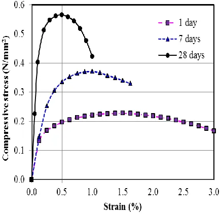
The strain after each loading increment was measured by reading on two dial gages, graduated in 0.01 mm. It can be observed that the longer ages the higher UCS was obtained along with a drastic change in shape of stress-strain curve, as typically shown in Fig. 1. The results imply that at early ages, CLSM behaves as a soil material with more ductile characteristic, but with long-term ages the material acts more like concrete, with higher strength and lesser strain (brittleness).Figure 1. Stressstrain response for Mix-1 at 1-, 7-, and 28 days.
(b) Modulus of elasticity of different mixtures
From the plot of obtained strain versus corresponding applied stress, the elastic modulus was calculated as the slope of the secant line drawn from the origin to a point on the stress-strain curve at 40% peak stress. The values of 28-day elastic moduli of all CLSM mixtures were displayed in Fig. 2. The B80 and B130 denote for mixture series containing 80 and 130 kg/m3, respectively.
Figure 2. 28-day Elastic moduli of CLSM with different mixtures
III. NUMERICAL ANALYSIS OF THE BACKFILLED ZONE 3.1 Problem description
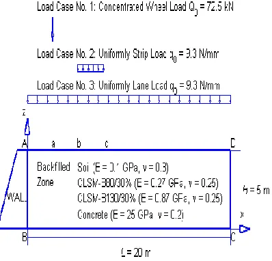
A backfilled zone with lengthL20m, height H 5m after a retaining wall is considered (Figure 3). Different backfilled materials will be investigated as follows: (1) Soil: E0.1GPa, 0.3;
(2) CLSM(B80/30%):E0.27GPa, 0.25;
(3) CLSM(B130/30%)E0.87GPa, 0.25;
(4) Concrete: E25GPa, 0.2.
We consider three loading conditions:
[image:2.612.58.275.251.462.2]International Journal of Emerging Technology and Advanced Engineering
Website: www.ijetae.com (ISSN 2250-2459,ISO 9001:2008 Certified Journal, Volume 4, Issue 12, December 2014)
134
(b) Load Case No. 2: vertical uniform strip load:m kN
q0 9.3 / distributed from bH to c1.5H
) 5 . 0
(bc H .
(c) Load Case No. 3: vertical uniform lane Load: m
kN
q0 9.3 / distributed on ADL4H .
[image:3.612.82.281.324.515.2]Load Case No. 1 and 3 are based on AASHTO LRFD Bridge Design Specifications (1998) [9]. Load Case No. 1 is equivalent to the single heaviest wheel load of a common AASHTO HS20 truck (or HL-93 truck in the AASHTO LRFD version).
Figure 3. Problem description
3.2 Basic assumptions
The basic assumptions of numerical analysis are: 1)Retaining wall is perfectly rigid;
2)Backfilled zone is homogeneous ad isotropic and is in the state of plane strain, material constants are assumed to be time-independent (quasi-steady);
3)Displacements perpendicular to the bottom, left-hand side and right-hand side boundaries of backfilled zone are fixed.
3.3 Finite element formulation
We can deduce the general finite element equations of equilibrium in the matrix form as [10]:
} { } ]{
[K x f (1)
Where [K]denotes the global stiffness matrix, {x} and }
{f denotes the nodal degrees of freedom ad nodal loads of the finite element system.
3.4 Boundary element formulation
The boundary element formulation for the problem can be expressed in matrix form as [11]:
} ]{ [ } ]{ [ } ]{
[H u G p C b (2)
in which [H],[G] denotes the influence matrices corresponding to the displacement and traction vectors,
}
{u and {p}, respectively.
ij G ij C i n j r j n i r n r j r i r ij r ij H j r i r ij r G ij G } ) , , )( 2 1 ( ] , , 2 ) 2 1 {[( ) 1 ( 4 11 ] , ln ) 4 3 [( ) 1 ( 8 1 (3)
IV. NUMERICAL RESULTS AND DISCUSSION 4.1 FE and BE meshes for the problem
International Journal of Emerging Technology and Advanced Engineering
Website: www.ijetae.com (ISSN 2250-2459,ISO 9001:2008 Certified Journal, Volume 4, Issue 12, December 2014)
135
Figure 4. 200 constant strain triangular (CST) finite element meshFigure 5. 50 constant boundary element mesh
Figure 6. 100 constant boundary element mesh
Figure 7. 200 constant boundary element mesh
4.2 Convergence tests
International Journal of Emerging Technology and Advanced Engineering
Website: www.ijetae.com (ISSN 2250-2459,ISO 9001:2008 Certified Journal, Volume 4, Issue 12, December 2014)
[image:5.612.64.270.146.330.2]136
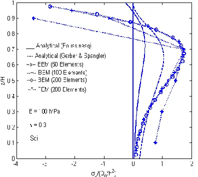
Figure 8. Settlement of backfilled zone under concentrated wheel loadFigure 9. Lateral wall pressure along retaining wall under concentrated wheel load
4.3 Comparison study of CLSM backfilled materials at different ages
From Figure 1 we can estimate the modulus of elasticity of CLSM Mixture-1 at different ages to be:
1 day: E120MPa0.12GPa
7 days: E140MPa0.14GPa
28 days: E470MPa0.47GPa
The Poisson’s ratios are all assumed to be 0.25. Figure 10 and Figure 11 show the BE results of CLSM at different ages using 200 constant elements.. It can be seen that 1-day and 7-days CLSM have nearly the same surface settlements as that of soil while 28-days CLSM gives less settlement. However, lateral wall pressures caused from all the CLSMs are a little greater than that of concrete but smaller than that of soil. In engineering practice more than 28-days curing is required for CLSM application.
Figure 10. Settlement of the backfilled zone under concentrated wheel load
[image:5.612.68.266.364.541.2]International Journal of Emerging Technology and Advanced Engineering
Website: www.ijetae.com (ISSN 2250-2459,ISO 9001:2008 Certified Journal, Volume 4, Issue 12, December 2014)
137
4.4 Comparison study of CLSM with different bindermixtures under various surface surcharges
We then study the mechanical behavior of different kinds of backfilled materials subjected to three different surface loading conditions. The material constants employed for comparison are shown in Figure 3 where two different binder mixtures for CLSM are emphasized: CLSM-B130/30% and CLSM-B80/30%.
4.4.1 Load case No. 1 (concentrated wheel load)
[image:6.612.341.540.148.357.2]Figure 12 shows that the surface settlements are influenced significantly by the modulus of elasticity (E). Both CLSMs depict smaller settlements than soil. In Figure 13 two kinds of CLSM and concrete depict the same smaller lateral wall pressures than soil. This is due to the effect of Poisson’s ratio rather than the modulus of elasticity.
Figure 12 Settlement of the backfilled zone under concentrated wheel load
Figure 13. Lateral wall pressure along retaining wall under concentrated wheel load
4.4.2 Load case No. 2 (uniform strip load)
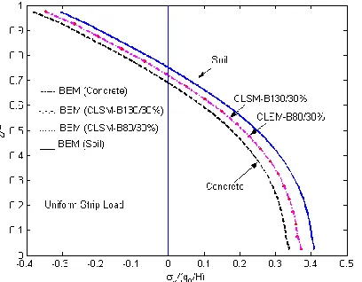
[image:6.612.63.271.349.560.2]Figure 14 and Figure 15 show the boundary element predictions on the surface settlements and lateral wall pressure of four kinds of backfilled materials under uniform strip load. It is noticed that, from Figure 10, settlement under loading area and heaving on two sides of strip load are less for both CLSMs than soil. Figure 11 also reveals that lateral wall pressure of CLSMs lie between that of concrete and soil.
[image:6.612.338.540.504.671.2]International Journal of Emerging Technology and Advanced Engineering
Website: www.ijetae.com (ISSN 2250-2459,ISO 9001:2008 Certified Journal, Volume 4, Issue 12, December 2014)
[image:7.612.67.271.145.304.2]138
Figure 15. Lateral wall pressure along retaining wall under uniformstrip load
4.4.3 Load case No. 3 (uniform lane load)
[image:7.612.337.550.146.292.2]Figure 16 shows different and reasonable surface settlement for 4 kinds of materials, with the maximal settlement ratio nearly to be 0.01, 0.1, 0.3, 0.7. Figure 17 also depicts more interesting result that in this loading case the lateral wall pressures caused by two CLSMs (1.05) are quite smaller than those by soil (1.38) and only lightly greater than those by concrete (0.81). If the Poisson’s ratios of CLSMs are 0.19, the maximal lateral wall pressures will be 0.75 and thus smaller than those by concrete (not shown here). The results shown in Figure 16 and 17 explain that the CLSM seems to be a very good candidate employed for backfilling materials.
Figure 16. Settlement of the backfilled zone under uniform lane load
Figure 17. Lateral wall pressure along retaining wall under uniform lane load
V. CONCLUDING REMARKS
Numerical results based on theory of elasticity show that boundary element method can provide a converged, satisfactory and efficient scheme for displacement and stress analysis of backfilled zone since in this problem most of interesting information lies on the boundary. This study also reveals that:
(a) lateral pressure exerted on the retaining wall by the backfilled materials mainly depends on the Poisson’s ratio,
, of the backfilled materials and it is in general that of CLSMs smaller than that of concrete. This reveals that CLSM is a good backfilling material if prepared well.(b) surface settlement of the backfilled zone depends on more the modulus of elasticity, E, than the Poisson’s ratio,
, of the backfilled materials. Settlement of CLSM backfilled zone lies between those of soil and concrete too.(c) Consideration of both lateral pressure on the wall and
surface settlement,
CLSM(B130/30%)(E0.87GPa, 0.25) shows to be a good material for backfilling construction.
Acknowledgements
[image:7.612.62.270.499.652.2]International Journal of Emerging Technology and Advanced Engineering
Website: www.ijetae.com (ISSN 2250-2459,ISO 9001:2008 Certified Journal, Volume 4, Issue 12, December 2014)
139
REFERENCES[1] ACI-229R, 2005. Controlled-low strength materials (Reproved 2005), Farmington Hills (MI).
[2] Lachemi, M. Şahmaran, M., Hossain, K. M. A. and Lotfy, A. 2010. Properties of controlled low-strength materials incorporating cement kiln dust and slag. Cement and Concrete Composites, 32, 623-629. [3] Finney, A.J., Shorey, E. F. and Anderson, J. 2008. Use of native soil
in place of aggregate in controlled low strength material (CLSM), International Pipelines Conference 2008, Atlanta, Georgia, United States, 1-13.
[4] Howard, A., Gaughan, M., Hattan, S., Wilkerson, M. 2012. Lean, Green, and Mean: The IPL Project. ICSDEC 2012: American Society of Civil Engineers, 359-366.
[5] Schmitz, M. E., Parsons, R. L., Ramirez, G. and Zhao, Y.2004. Use of controlled low-strength material as abutment backfill, Technical Report K-TRAN: KU-02-6, The Kansas Department of Transportation, Topeka, Kansas, University of Kansas, U.S.A. [6] Sheen, Y. N., Huang, L. J. and Le, D. H. 2014. Engineering
properties of controlled low-strength material made with residual soil and Class F fly ash, 3rd International Conference for Advanced Materials Design and Mechanics and Workshop on Android Robotics, Singapore, May 23-24.
[7] Huang, L. J., Sheen, Y. N. and Le, D. H. 2014. On the multiple linear regression and artificial neural networks for strength prediction of soil-based controlled low-strength material, 3rd International Conference for Advanced Materials Design and Mechanics and Workshop on Android Robotics, Singapore, May 23-24..
[8] Sheen, Y. N., Hsiao, D. H., Huang, L. J. and Le, D. H. 2014. Stress-strain behavior of soil-based controlled low-strength material, the International Conference on Green Technology for Sustainable Development 2014, Ho Chi Minh, Viet Nam, October 30 - 31. [9] American Association of State Highway ad Transportation Officials.
1998. LRFD Bridge Design Specification, 2nd edition, Washington D. C..
[10] Rao, S. S. 1982. The Finite Element Method in Engineering, Pergamon Press..
[11] Brebbia, C. A. and Walker, S. 1980. Boundary Element Techniques in Engineering, Newnes-Butterworths..
[12] Das, B. M. 1990. Principles of Geotechnical Engineering, 5th edition, International Thomson Publishing.
[13] Boussinesq, J. 1983. Application des Potentials L’Equilibre et du Mouvement des Solides Elastiques, Gauthier-Villars, Paris. [14] Gerber, E. 1929. Untersuchhungen über die Druckvertelung im
Örlich belasteten Sand, Technisch Hochschule, Zurich.