International Journal of Emerging Technology and Advanced Engineering
Website: www.ijetae.com (ISSN 2250-2459, ISO 9001:2008 Certified Journal, Volume 7, Issue 3, March 2017)
139
Real Time Implementation of PV Fed IEEE Bus System
Interfaced by 3-Phase 4-Leg Inverter Using OPAL-RT
Prashant Kumar
1,
Shimi S. L
2, Arindam Chowdhury
3 1,3ME Student, Electrical Engineering, NITTTR, Chandigarh2Assistant Professor, Electrical Engineering, NITTTR, Chandigarh
Abstract- In recent years, with the advancement of power
electronic technology, the expenses of renewable energy technology has decreased so that applications can be economically justified by utility. Renewable energy electric generations are being used increasingly interconnected in distributed network with the use of power electronic converters in reasonable way since it is placed near the load with more efficient operation. This paper represents 3-phase 4-leg interfacing inverter to interface renewable energy sources (RESs) to electric power system (EPS) in which PV is interconnected to IEEE 14 bus system. The PV system which is integrated to distributed network with 3-phase 4-leg interfacing inverter, is analyzed for voltage profile of each bus along with active and reactive power flow at each bus of IEEE 14 bus system using MATLAB/SIMULINKTM software. The
real-time voltage profile, active and reactive power flow is also analyzed by OPAL-RT which is PC/FPGA based Real-Time Digital Simulator (RTDS).
Keywords: Renewable Energy Sources (RES), Photovoltaic
(PV), Electric Power System (EPS), Point of Common Coupling (PCC), Custom Power Device (CPD), Real-Time Digital Simulator (RTDS)
I. INTRODUCTION
Dearth of conventional fossils fuel and their higher emissions are the twin concern for centralized power generation. To meet the energy demand and to have sustainable growth and social progress, it is obligatory to utilize RESs like Solar, Wind, Hydro, Biomass, Cogeneration etc. [1].
Energy requirement cannot be meet by RESs alone since RESs can be used as hanging energy sources which will work in coordination with existing conventional plants so it is necessary to integrate power sources from renewable sources like solar and wind into power network to reduce environmental impact of already existing conventional plant such as thermal, hydral etc.
The integration of RESs adds on some power quality issues to power network such as voltage regulation, harmonic distortion, flicker, stability, distortion, etc., these power quality issues are to be confined to IEC and IEEE standards.
Due to the intermittent and unpredictable nature of sources, mainly sun or wind, integration of RESs in smart grid is a challenging task. Research in this field divulge that there may occur power quality issues at the generation, transmission and distribution [2]. IEEE-519 standard is widely accepted for power quality at the point of common coupling (PCC) with the utility grid [3]. Some remedies to these power quality problems are investigated in the literature [4]. Custom Power Devices (CPDs) are used for compensation of the power quality problems in the current, voltage and both current and voltage respectively.
Different Power Quality issue has been discussed in [5]. Researchers presented control strategy to improve PQ of electric power system (EPS) for achieving maximum benefits from grid-interfacing.
International Journal of Emerging Technology and Advanced Engineering
Website: www.ijetae.com (ISSN 2250-2459, ISO 9001:2008 Certified Journal, Volume 7, Issue 3, March 2017)
140
Fig.1 Schematic of Renewable Based Distributed Generation System [8],[12]
Since 4 leg VSI has advantageous over both 2 leg inverter and UPQC [9], [13], [14], [15] in terms of operating voltage and inherent property of 4th leg in compensating neutral current, hence the proposed model use 3-phase 4-leg interfacing inverter for interconnection of RES with existing grid. Hysteresis control method is being used which compare actual current and reference current of inverter to give gate pulse.
Fig.1 shows the schematic diagram of proposed RES based generation system. The proposed model is simulated by considering PV as RES for distributed generation.
OPAL-RT is PC/FPGA based Real-Time Digital Simulators, Hardware-In-the-Loop (HIL) testing equipment and Rapid Control Prototyping (RCP) systems. Real-time hardware based simulation platforms enable model execution at the same rate as actual time [16].
OPAL-RT provides a complete range of real-time digital simulators and control prototyping systems for power grids, power electronics, motor drives and other mechatronic systems. In addition, the RT-LAB, core OLAP-RT software, enables user to develop models for real-time simulation [17]. These real-time systems help to perform feasibility studies, develop new concepts, design and test controllers for a wide variety of applications including small power converters, hybrid electric drives, large power grids and renewable energy systems. Hence, OPAL-RT is a solid alternative to overpriced Real-Time Digital Simulators.
Fig.2 Schematic of OPAL-RT Implementation
In this paper, PV is integrated at bus 9 of IEEE 14 bus system and its real-time implementation is analyzed using OPAL-RT for voltage profile, active and reactive power flow.
II. OPERATING PRINCIPAL
The single phase equivalent circuit for R phase of system is shown in Fig. 3.
Fig.3 Single Phase Equivalent Circuit of the System and VSI
Load current for R phase can be written as
𝐼𝐿𝑅= 𝐼𝐿𝑅𝑓+ 𝐼𝐿𝑅ℎ (1)
𝐼𝐿𝑎 = 𝐼𝐼𝑛𝑣𝑅+ 𝐼𝑠 (2)
ILR IInvR I
s
S4 S1
𝑉
𝑅+
~International Journal of Emerging Technology and Advanced Engineering
Website: www.ijetae.com (ISSN 2250-2459, ISO 9001:2008 Certified Journal, Volume 7, Issue 3, March 2017)
141
Where, 𝐼𝐿𝑅𝑓 is the fundamental component and 𝐼𝐿𝑅ℎharmonic component of load current. Since supply side should be free the harmonic component of load current, the inverter has to inject a current whose magnitude should be equal to harmonic component.
This condition should be satisfied,
𝐼𝐿𝑅ℎ = 𝐼𝐼𝑛𝑣𝑅 (3)
From equation (2) and (3),
𝐼𝑠 = 𝐼𝐿𝑅𝑓 (4)
If 𝐼𝐿𝑅ℎ > 𝐼𝐼𝑛𝑣𝑅 S4 should be OFF and S1 should be ON so the current generated by dc capacitor 𝐼𝐼𝑛𝑣𝑅 is equal to 𝐼𝐿𝑅ℎ.
If 𝐼𝐿𝑅ℎ < 𝐼𝐼𝑛𝑣𝑅 S4 should be ON and S1 should be OFF so the current 𝐼𝐼𝑛𝑣𝑎 should be transferred to the ground in order to
have 𝐼𝐼𝑛𝑣𝑅= 𝐼𝐿𝑅ℎ.
III. CONTROL STRATGY
A Phase Locked Loop (PLL) is used to extract the pure sinusoidal signal at fundamental frequency. The output of the PLL gives 𝑈𝑅 (unit vector for phase R) which is
expressed mathematically as,
𝑈𝑅= sin(ω𝑡) (5)
The unit vector for phase Y and phase B can be obtained by proper phase shifting and is expressed as,
𝑈𝑌= sin(ω𝑡 − 120) (6)
𝑈𝐵= sin(ω𝑡 + 120) (7)
The dc-link voltage (𝑉𝑑𝑐) is passed through a first-order
low pass filter (LPF) in order to eliminate the switching ripples on the dc-link voltage and in the generated reference current signals. The difference of this filtered dc-link voltage (𝑉∗
𝑑𝑐) and reference dc-link voltage is passed through a
discrete-PI regulator to maintain a constant dc-link voltage under varying generation and load conditions. The dc-link voltage error 𝑉dcerr(n) at 𝑛th sampling instant is given as,
𝑉dcerr(n)= 𝑉∗𝑑𝑐(𝑛)− 𝑉𝑑𝑐(𝑛) (8)
The output of discrete-PI regulator at nth sampling instant is expressed as,
𝐼𝑚(𝑛)= 𝐼𝑚(𝑛−1)+ 𝐾𝑃𝑉𝑑𝑐(𝑉𝑑𝑐𝑒𝑟𝑟(𝑛)− 𝑉𝑑𝑐𝑒𝑟𝑟(𝑛−1)) +
𝐾𝐼𝑉𝑑𝑐𝑉𝑑𝑐𝑒𝑟𝑟(𝑛) (9)
Where, 𝐾𝑃𝑉𝑑𝑐 and 𝐾𝐼𝑉𝑑𝑐 are proportional and integral
gains of dc-voltage regulator.
The peak amplitude (𝐼𝑚) is then multiplied with unit
vector templates giving reference current signals for shunt APF.
The reference three phase grid currents are enumerated as their instantaneous values as
𝐼∗
𝑅= 𝐼𝑚− 𝑈𝑅 (10)
𝐼∗
𝑌= 𝐼𝑚− 𝑈𝑌 (11)
𝐼∗
𝐵= 𝐼𝑚− 𝑈𝐵 (12) The forth leg of grid-interfacing inverter compensates neutral currents if presents due to loads connected to neutral conductor since it should not be drawn from the grid. In other words, the reference current for the grid neutral current is considered as zero and can be expressed as,
𝐼∗
𝑛= 0 (13)
The reference grid currents (𝐼∗
𝑅, 𝐼∗𝑌, 𝐼∗𝐵 and 𝐼∗𝑛 ) are
compared with actual grid currents (𝐼𝑅, 𝐼𝑌, 𝐼𝐵 and 𝐼𝑛) to
compute the current errors as,
𝐼𝑅𝑒𝑟𝑟= 𝐼∗𝑅− 𝐼𝑅 (14)
𝐼𝑌𝑒𝑟𝑟= 𝐼∗𝑌− 𝐼𝑌 (15)
𝐼𝐵𝑒𝑟𝑟= 𝐼∗𝐵− 𝐼𝐵 (16)
𝐼𝑛𝑒𝑟𝑟 = 𝐼∗𝑛− 𝐼𝑛 (17)
These current errors are given to hysteresis current controller which then generates the switching pulses (𝑃1to
𝑃8) for the gate drives of grid-interfacing inverter as shown
in Fig. 4.
International Journal of Emerging Technology and Advanced Engineering
Website: www.ijetae.com (ISSN 2250-2459, ISO 9001:2008 Certified Journal, Volume 7, Issue 3, March 2017)
142
The average model of 4-leg inverter can be obtained by the following state space equations𝑑𝐼𝐼𝑛𝑣𝑅
𝑑𝑡 =
(𝑉𝐼𝑛𝑣𝑅−𝑉𝑅)
𝐿𝑠ℎ (18)
𝑑𝐼𝐼𝑛𝑣𝑌
𝑑𝑡 =
(𝑉𝐼𝑛𝑣𝑌− 𝑉𝑌)
𝐿𝑠ℎ (19)
𝑑𝐼𝐼𝑛𝑣𝐵
𝑑𝑡 =
(𝑉𝐼𝑛𝑣𝐵− 𝑉𝐵)
𝐿𝑠ℎ (20)
𝑑𝐼𝐼𝑛𝑣𝑛
𝑑𝑡 =
(𝑉𝐼𝑛𝑣𝑛−𝑉𝑛)
𝐿𝑠ℎ (21)
𝑑𝑉𝑑𝑐
𝑑𝑡 =
(I𝐼𝑛𝑅𝑑+I𝐼𝑛𝑌𝑑+𝐼𝐼𝑛𝐵𝑑+𝐼𝐼𝑛𝑛𝑑)
𝐶𝑑𝑐 (22)
Where, 𝑉𝐼𝑛𝑣𝑅, 𝑉𝐼𝑛𝑣𝑌, 𝑉𝐼𝑛𝑣𝐵, 𝑉𝐼𝑛𝑣𝑛, are the three-phase ac
switching voltages generated on the output terminal of inverter. These inverter output voltages can be modelled in terms of instantaneous dc bus voltage and switching pulses of the inverter as,
𝑉𝐼𝑛𝑣𝑅= (𝑃1−𝑃4)
2 𝑉𝑑𝑐 (23)
𝑉𝐼𝑛𝑣𝑌= (𝑃3−𝑃6)
2 𝑉𝑑𝑐 (24)
𝑉𝐼𝑛𝑣𝐵= (𝑃5−𝑃2)
2 𝑉𝑑𝑐 (25)
𝑉𝐼𝑛𝑣𝑛= (𝑃7−𝑃8)
2 𝑉𝑑𝑐 (26)
Similarly the charging currents 𝐼𝐼𝑛𝑣𝑎𝑑, 𝐼𝐼𝑛𝑣𝑏𝑑, 𝐼𝐼𝑛𝑣𝑐𝑑 and
𝐼𝐼𝑛𝑣𝑛𝑑 on dc bus due to the each leg of inverter can be
expressed as,
𝐼𝐼𝑛𝑣𝑅𝑑 = 𝐼𝐼𝑛𝑣𝑅(𝑃1− 𝑃4) (27)
𝐼𝐼𝑛𝑣𝑌𝑑 = 𝐼𝐼𝑛𝑣𝑌(𝑃3− 𝑃6) (28)
𝐼𝐼𝑛𝑣𝐵𝑑= 𝐼𝐼𝑛𝑣𝐵(𝑃5− 𝑃2) (29)
𝐼𝐼𝑛𝑣𝑛𝑑 = 𝐼𝐼𝑛𝑣𝑛(𝑃7− 𝑃8) (30)
The switching pattern of each IGBT inside inverter can be formulated on the basis of error between actual and reference current of inverter, which can be explained as,
a. If, 𝐼𝐼𝑛𝑣𝑅< (𝐼∗𝐼𝑛𝑣𝑅− ℎ𝑏) then upper switch 𝑆1 will be
OFF (𝑃1= 0) and lower switch 𝑆4 will be ON (𝑃4=
1) in the phase “a” leg of inverter.
b.If,𝐼𝐼𝑛𝑣𝑅> (𝐼∗𝐼𝑛𝑣𝑅− ℎ𝑏) then upper switch 𝑆1 will be
ON (𝑃1= 1) and lower switch 𝑆4 will be OFF (𝑃4=
0) in the phase “a” leg of inverter.
Where, ℎ𝑏is the width of hysteresis band. On the same
principle, the switching pulses for the other remaining three legs can be derived.
IV. MATHEMATICAL MODEL
The proposed model consists of PV system with their MPPT so that maximum power can be tracked under given temperature and solar insolation. PV is a dc source of energy hence dc-ac converter is needed. 3-phase 4-leg interfacing inverter is designed in SIMULINK for the dc-ac conversion as well as controlling the aspects of existing grid at the instant of interconnection. The controlling action is achieved by switching pulse of IGBTs of interfacing inverter. In this paper a MATLAB/SIMULINK model is modelled in which RES is integrated to bus 9 of the existing IEEE 14 bus network. Fig.5 is the MATLAB model of interfacing inverter and Fig.6 is the model for switching pattern of interfacing inverter.
Fig.5 SIMULINK Model of 3-Phase 4-Leg Grid Interfacing Inverter.
International Journal of Emerging Technology and Advanced Engineering
Website: www.ijetae.com (ISSN 2250-2459, ISO 9001:2008 Certified Journal, Volume 7, Issue 3, March 2017)
143
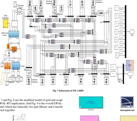
[image:5.612.74.541.161.573.2]Fig. 7 Subsystem of SM_GRID
Fig. 7 and Fig. 8 are the modified model of grid and scope after RT implication. And Fig. 9 is the overall OPAL-RT model which has basically two part Master and Console connected together.
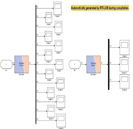
Fig. 8 Subsystem of SC_SCOPE
Fig. 9 OPAL-RT Model of PV Integrated System
[image:5.612.63.272.550.706.2]International Journal of Emerging Technology and Advanced Engineering
Website: www.ijetae.com (ISSN 2250-2459, ISO 9001:2008 Certified Journal, Volume 7, Issue 3, March 2017)
[image:6.612.61.277.125.324.2]144
Fig. 10 OPAL-RT Model Interfaced with OP4510V. SIMULATION RESULT
PV is interconnected to the existing IEEE 14 bus system at t=0.7s. The simulation result for bus no 9 of IEEE bus network is shown in Fig. 12. It can be seen that at t=0.7, transient condition has occurred and later it saturates with some disturbance in their waveform.
[image:6.612.334.554.165.450.2]Fig. 11 is the confirmation pop-up window which is automatically generated by OPAL-RT after the model is built and loaded to OP4510.
Fig. 11 New Console Automatically Generated by OPAL-RT
The OPWRITE block help to save all the measurement data of SC_SCOPE which is later plotted and analyzed.
[image:6.612.61.273.466.672.2]Fig.12 Voltage Waveform at Bus 9
Fig. 13 shows the voltage magnitude (pu) of all buses of IEEE 14 bus network obtained from SIMULINK result, OPAL-RT result and by the Newton Rapshon (N.R) method and their relative error is shown in Fig. 14.
[image:6.612.339.554.523.676.2]International Journal of Emerging Technology and Advanced Engineering
Website: www.ijetae.com (ISSN 2250-2459, ISO 9001:2008 Certified Journal, Volume 7, Issue 3, March 2017)
[image:7.612.338.548.142.268.2]145
Fig.14 Voltage ErrorFrom Fig.14 it is seen that the difference in voltages of both MATLAB/SIMULINK and OPAL-RT. It shows the error in voltage at each bus is less. This validate the proposed model.
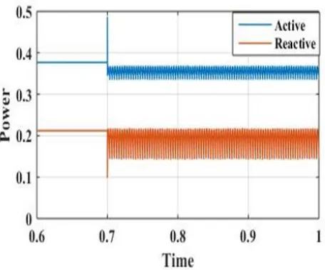
[image:7.612.66.269.145.321.2]Active and Reactive power flow through each bus is analyzed. Fig.15 shows power flow at bus 9 having transient at t=0.7 when RES is integrated and a slight difference with fluctuation after interconnection.
[image:7.612.330.553.340.495.2]Fig.15 Active and Reactive power flow at Bus
Fig. 16 is shown represents that the voltage across dc link of the RES is constant which is desired for RESs like PV sources.
Fig.16 Voltage across dc Link
Fig. 17 is the current fed to grid from RES. Before 0.7s, the current fed from PV is zero then after circuit is made at the instant of 0.7s, sinusoidal waveform is generated by interfacing inverter.
Fig. 17 Current Fed to Grid from PV
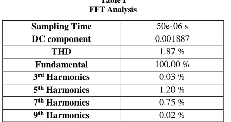
FFT analysis of voltage waveform at bus 9 for one cycle is analyzed in Fig.18 and the result is shown in Table 1.
[image:7.612.56.284.433.622.2] [image:7.612.335.542.566.686.2]International Journal of Emerging Technology and Advanced Engineering
Website: www.ijetae.com (ISSN 2250-2459, ISO 9001:2008 Certified Journal, Volume 7, Issue 3, March 2017)
[image:8.612.58.283.139.258.2]146
Table IFFT Analysis
Sampling Time 50e-06 s DC component 0.001887
THD 1.87 %
Fundamental 100.00 % 3rd Harmonics 0.03 %
5th Harmonics 1.20 %
7th Harmonics 0.75 %
9th Harmonics 0.02 %
From FFT analysis it is seen that THD is 1.87 % (less than 5 %) which is in permissible limit which also validate the proposed model.
VI. CONCLUSION
This paper has presented an interconnection model of PV system to existing IEEE 14 bus network using 3-phase 4-leg interfacing inverter while maintaining voltage profile of the distributed network. From the simulation result and OPAL-RT implementation of the model, it can be concluded that 3-phase 4-leg grid interfacing inverter can be effectively utilized for existing bus network interconnection maintaining voltage profile of the network.
REFERENCES
[1] Kerekes, T. Sera, D. Teodorescu, R., "Overview of Recent Grid Codes for PV Power Integration," IEEE Conference in Optimization of Electrical and Electronic Equipment, Brasov, pp.959-965, 24-26 May 2012.
[2] El-Samahy, El-Saadany, "The Effect of DG on Power Quality in a Deregulated Environment," IEEE Conference in Power Engineering Society General Meeting, San Francisco, pp.2969-2976, 12-16 June 2005.
[3] “IEEE Recommended Practices and Requirements for Harmonic Control in Electrical Power Systems 519-1992”, IEEE Industry Application Society, pp.1-112, 9 April 1993.
[4] S. K. Khadem, M. Basu, and M. F. Conlon, “Power Quality in Grid Connected Renewable Energy Systems : Role of Custom Power Devices”, International Conference on Renewable Energies Power Quality, Granada Spain, pp. 1-6, 2010.
[5] K. S. V. P. Kumar and S. Venkateshwarlu, “A Review on Power Quality in Grid Connected Renewable Energy System”, CVR Journal of Science and Technology, Vol. 5, pp.1-6, December, 2013.
[6] R.Teodorescu, F.Blaabjerg U. Borup M. Liserre,” A New Control Structure for Grid-Connected LCL PV Inverters with Zero Steady-State Error and Selective Harmonic Compensation”, IEEE Conference on Applied Power Electronics Conference and Exposition, Anaheim, California, Vol.1, pp. 580-586, 2004. [7] Xiaoming Yuan, Willi Merk, Herbert Stemmler, and Jost Allmeling, ”Stationary-Frame Generalized Integrators for CurrentControl of Active Power Filters With Zero Steady-State
Error for Current Harmonics of Concern Under Unbalanced and Distorted Operating Conditions”, IEEE Transactions on Industry Applications, Vol. 38, No. 2, March/April 2002.
[8] M. E Meral, A Teke, K. C Bayindir, M Tumay, “Power Quality Improvement with an Extended Custom Power Park”, Electric Power Systems Research, Vol. 79, pp 1553–156, 2009.
[9] Modesto, R.A.; Oliveira da Silva, S.A.; Albano de Oliveira Júnior, A., "Power Quality Improvement Using a Dual Unified Power Quality Conditioner/Uninterruptible Power Supply in Three-Phase Four-Wire Systems", IEEE Conference in Power Electronics, Vol.8, No.9, pp.1595-1605, September 2015. [10] M. Singh, V. Khadkikar, A. Chandra, and R. K. Varma, “Grid Interconnection of Renewable Energy Sources at the Distribution Level with Power-Quality Improvement Features”, IEEE Transactions on Power Delivery, Vol. 26, No. 1, pp. 307–315, 2011.
[11] S. Premalatha, S. S. Dash, and P. C. Babu, “Power Quality Improvement Features for a Distributed Generation System Using Shunt Active Power Filter”, International Conference on Design and Manufacturing, Kancheepuram, Vol. 64, pp. 265–274, June 2013.
[12] V.Ilavarasi, C.Christober Asir Rajan, “Power Quality Improvement in Grid Connected System Using Four Leg VSI”, IEEE Conference on Advances in Engineering, Science and Management , pp. 540-546, Tamil Nadu , March 2012.
[13] Maoh Chin Jiang, “Analysis and Design of a Novel Three-Phase Active Power Filter”, IEEE Transactions on Aerospace and Electron Systems, Vol. 37, No. 3, pp. 824-831, July 2001. [14] Y. Li, D. M. Vilathgamuwa, and P. C. Loh, “Microgrid Power Quality Enhancement Using a Three-Phase Four-Wire Grid-Interfacing Compensator”, IEEE Transactions on Industrial Application, Vol. 41, No. 6, pp. 1707–1719, 2005.
[15] Jayaprakash, P.; Singh, B.; Kothari, D.P., "Three-Phase 4-Wire DSTATCOM Based on H-Bridge VSC with a Star/Hexagon Transformer for Power Quality Improvement", IEEE Conference on Industrial and Information Systems, Kharagpur, pp.1-6, 8-10 December 2008.