International Journal of Emerging Technology and Advanced Engineering
Website: www.ijetae.com (ISSN 2250-2459,ISO 9001:2008 Certified Journal, Volume 4, Issue 3, March 2014)
16
Implementation of Efficient CT Reconstruction From
Projection By A Discrete Radon Transform Using FRA
Chinchu Thangam Chacko
1, Vaisakhi.V.S
21
ME communication systems, NIET, Coimbatore, India
2Asst. professor, ECE, NIET Coimbatore, India
Abstract -Tomography refers to imaging by sections or sectioning using any kind of penetrating wave .when x-ray is used for tomography called computed tomograhy(CT). The Radon transform is widely app-licable to tomography, which means an image is created from the scattering data associated with cross-sectional scans of an object. The Discrete Radon Transform (DRT) was defined as an analog of the continuous Radon transform for discrete data. In this paper we demonstrate the applicability of Fourier Reconstruction Algorithm (FRA) for the reconst-ruction of a 2-D object from its projection. The DRT and its inverse are shown more accurate as the number of samples increases. we can use either parallel projection or fan-beam projection for acquisition purpose. Numerical results for reconst-ruction using FRA are presented. We also shown that the FRA can be used for reconstruction from fan-beam projections.
Index Terms- Computed tomography(CT), Discrete Radon Transform(DRT), Fourier Reconstruction Algorithm(FRA), parallel projections, fan-beam projections, Fast Fourier Transform(FFT).
I. INTRODUCTION
Tomography is a non-invasive imaging technique allowing for the visualization of the internal structure of an object without the superposition of over and under-lying structures. A computed tomography (CT) slice captures each image in its actual dimensional position. Tomographic recons-truction underlies nearly all diagnostic imaging modalities, including X-ray computed tomography (CT), positron emission tomography, single-photon emission tomography, and certain acquisition methods for magnetic resonance imaging. Also, It is widely used for non-destructive evaluation in manufacturing and, more recently, for airport baggage security[2]. Image reconstruction in CT is a mathematical process that generates images from X-ray proj-ection data acquired at many different angles around the patient. Image reconstruction has a essential impact on image quality and therefore on radiation dose. It is desirable to reconstruct images with the lowest possible noise without sacrificing image quality and resolution, for a given radiation dose. Images of acceptable quality can be reconstructed at lower dose.
Reconstruction in tomography means a recovery from samples of either the X-ray transform (set of line-integral projections) or the Radon transform (set of integrals on planes) of an unknown object density distribution. This is same in 2-D case. In CT reconstruction
f x y
( , )
is the distribution of the x-ray attenuation coefficient within the object. The aim of CTimaging is to reconstruct
f x y
( , )
from the projections of the object, each projection is the collection of line integrals. Two commonly used acquisition geometries are parallel and fan-beam projections. Parallel beam projection can be represented in terms of radon transformas
f
( , )
s
with fixed θ and varying s. From a single source, fan-beam projection are formed a line integrals along rays.In parallel geometry a projection consists of a collection of line integrals taken along straight parallel line in the plane lines. In fan-beam a single source of radiation is used. The vertex point is the converging point of the line integrals in a fan-beam projection, and the vertex path is the trajectory along which the projections are measured.
Speedups in computations to recover objects from projections (either parallel or fan beam) are important for next-generation real time imaging processes. Several fast reconstruction algorithms have been proposed. S. Babu and Y. Bresler [8],[10] uses fast hierarchical algorithms for tomographic reconstruction where filtered back projection (FBP) is the reconstruction method. Other fast reconstruction
algorithms which exhibit
o n
(
2log )
n
complexity have been proposed. One of them is multilevel inversion (MI) algorithm. MI is based on back projection. A back projection is the sum of back projected single projections,each at direction
p. Now, the back projected projectionvaries only in the
p direction, and is constant in theInternational Journal of Emerging Technology and Advanced Engineering
Website: www.ijetae.com (ISSN 2250-2459,ISO 9001:2008 Certified Journal, Volume 4, Issue 3, March 2014)
17
In this paper, we propose an approach to reconstruct an image using Fourier reconstruction algorithm (FRA). FRA are based on the Fourier slice theorem [3], which states that the Fourier transform of a projection at angle θ is a radial slice through the 2-D Fourier transform of the object at direction θ. The Fourier slice theorem build a polar 2-D Fourier space from the 1-D transformed projections of the scanned object, that is re-sampled into a Cartesian grid. Inverse 2D Fourier transform eventually yields the recons-tructed image.
A model for finite Radon transforms that is composed of Radon projections is presented in [15]. They do not interpolate between points, but they perform summation over lines with “wrap-around”. In some discretizations, “wraparound” is inherent, and this is a major drawback since algorithms, which are based on summation along wrapped lines, cannot be used for reconstruction from continuous projections.
A Fourier based iterative reconstruction techni-que, termed Equally Sloped tomography (EST) [11], is developed in conjunction with advanced mathematical regularization to investigate radiation dose reduction in x-ray CT. Radon transform is preferable here for reconstruction because of two reasons: 1) correctly sampled projection reconstr-uction exhibits virtually no visible artifacts apart of a smoothing caused by the aperture function. 2) the FRA algorithm is faster than the iterative procedure used in FBP.
The reconstruction procedure presented in this paper shows that this algorithm is faster and easier than other algorithms used in [8] and [11], with little or no added artifact, and also less complexity. In the proposed paper we review the application of Fourier theory to the field of tomo-graphy, both for projection and reconstruction. We address the basics of direct Fourier method as well as some implementations.
II.BASICS OF TOMOGRAPHY
Tomography refers to imaging by sections or sectioning, by the use of any kind of penetrating wave. A device used for tomography is called a tomograph, while the image produced is a tomogr-aphy. Tomography as the computed tomographic (CT) scanner was invented by Sir Godfrey Hounsfield, and thereby made an large contribution to medicine. The method is used in radiology, archaeology, biology, geophysics, materials science, astrophysics, quantum Information, and other sciences. In most cases it is based on the mathematical procedure called tomographic recon-struction. In tomography the distribution of a parameter on a transversal section of an object can be modeled as a 2-D
function
f
(object function) in the( , )
x y
plane of the section.For example in most of the medical applications, the function
f
is limited in space, which means that it vanishes outside a finite region of the plane.It consist of two parameters θ (slope of the line +
/ 2
) and s (distance to the center of rotation) specify the line with equationcos
sin
x
y
x
(1.1)in the (x, y) plane and the general formula for line integral , known as the Radon transform of f(x, y) , is
( , )
( , ) ( cos
sin
)
p
s
f x y
x
y
s dxdy
(1.2)
A projection consist of a collection of integrated values of f(x, y) taken along a set of straight lines in the plane and the projection data set is given by a number of projections taken with different orientations. Basically, two geometries have been defined for the set of line integrals making a 2-D projections: 1)Parallel projection, 2)Fan-beam pro-jection(divergent projection).In parallel
projection, a projection
p s
( )
consists of a collection of line integral taken along straight parallel lines in the plane, that means a collection of p(θ, s) with constant θ(fig.1) and
,
2 2
s s
s
.Fig.1. An object f(x, y) and its parallel projection
p s
( )
In divergent geometry, each angular position of the focus corresponds a fan of focus detector lines (the detector being an array of detector element). Here, each
line is defined by a pair of parameter
( , )
, where β is the slope of the central line of the beam +2
and γ is the
angular offset of the line relative to the central one (fig.2). Being
the fan-angle and r focus-center of rotation distance, the equation of the line iscos(
)
sin(
)
sin
x
y
r
(1.3) and each divergent projection is described by the formula :International Journal of Emerging Technology and Advanced Engineering
Website: www.ijetae.com (ISSN 2250-2459,ISO 9001:2008 Certified Journal, Volume 4, Issue 3, March 2014)
18
( )
( , ) ( cos(
)
sin(
)
sin )
p
f x y x
y
r
dxdy
(1.4)With constant β and
1 1
,
2 2
.Fig.2. An object f(x, y) and its fan-beam projection
p
( )
The radon function computes the line integral from multiple sources along parallel paths, or beams in a certain direction. To represent an image, the radon function takes multiple parallel beam projections of the image from different angles by rotating the source around the center of the image. In case of fan-beam function, it computed projections of an image matrix along specified directions. From a single source radiation, the fan-beam function computes the line integrals along paths , forming a fan shape. To represent an image, the fan-beam function takes multiple projections of the image from different angles by rotating the source around the center of the image.
III. TWO-DIMENSIONAL DRT
In the 2-D ,the radon transform, the Radon transform of a function
f x y
( , )
, denoted by
f
( , )
s
,is defined as the line integral off
along a line L inclined at angle θ and at distances from the orgin. Formally( , )
f
s
=L
f(x, y)du=
f(x, y)( x cos𝜃 +y sin𝜃-s)dxdy(3.1)
Where 𝛿(x) is Dirac’s delta function [1],[3].
The Radon transform provide the mathematical basis for reconstructing tomographic images from measured projection or scattering data. Generally speaking, the DRT is defined by summing the discrete samples of an
image
I u v
( , )
along lines with absolute slope less than 1. Two forms of lines are considered here:1) The line of the form
y
sx t s
(
1)
,basically a horizontal line , and 2) The line of the form' ' '
(
1)
x
s y t s
, basically a vertical line. In case ofbasic horizontal lines, we transverse each lines by unit
horizontal steps
,....,
1
2
2
n
n
x
, and for each x, weinterpolate the image sample at position (x, y) by using trigonometric interpolation along the corresponding image column. In case of basic vertical lines, we
interpolate the line equation
y
sx t s
(
1)
as' '
(
'1)
x
s y t s
. In this case we transverse eachlines by unit vertical steps, and for each integer y, we interpolate the value at x coordinate by using trigonometric int-erpolation along the corresponding image row. Using this families of lines, a formal definition of Radon transform from [6] for discrete images is provided in the following.
Definition III.1: 2-D Radon transform: Let
I u v
( , )
,where
,
,...,
1
2
2
n
n
u v
, be ann n
array .Let sbe a slope such that
s
1
,and let t be an intercept such thatt
n
,...,
n
.Then
2 11
2
, ( , ) (3.2)
n
n u
Radon y sx t I I u su t
%
2 12
2
, ( , ) (3.3)
n
n v
Radon x sy t I I sv t v
% Where
,
,...,
1, ,
2
2
n
n
u v
x y
¡
1 2 1
2
( , )
( , )
(
) (3.4)
n
m n
v
I u y
I u v D
y v
%
1 2 2 2( , )
( , )
(
) (3.5)
n
m n
u
I
x v
I u v D x u
%
sin(
)
,
2
1 (3.6)
sin(
/ )
m
t
D
t
m
n
m
t m
International Journal of Emerging Technology and Advanced Engineering
Website: www.ijetae.com (ISSN 2250-2459,ISO 9001:2008 Certified Journal, Volume 4, Issue 3, March 2014)
19
For an arbitrary line l with slope s and intercept t, such that
s
1
and t=-n,…..,n, the Radon transform is given by
( , ), ( )( , )
( , ),
Radon y sx t I l is basically horizontal line RI s t
Radon x sy t I l is basically vertical line
(3.7)
1
I
%
and2
I
%
in Eqn.(3.4) and (3.5) are column-wise and row-wise interpolated version of I , respectively, using the Dirichlet KernalD
mwith m=2n+1.The function
f
( , )
s
is often referred to as a sinogram because the Radon transform of an off center point source is a sinusoid. A typical slice image and its Radon transform are shown in Fig.3, here we take a standard test image known as Shepp-Logan phantom is used as a slice image. It serves as the model of a human head in the development and testing of image reconstruction algorithms, the advantage of Shepp-Logan is that an analytic expression for its projections can be derived.Fig.3. Shepp-Logan phantom and its Radon transform
The task of tomographic reconstruction is to find f(x, y) from the radon projection
f
( , )
s
.The sinogram( , )
f
s
has many mathematical properties , an important one of which is( , )
(
,
) (3.8)
f
s
s
The 2-D discrete definition of the Radon transform is shown in [6], where the lines used for the summation exhibit no wraparound effect and also it satisfies a Fourier slice theorem. Fourier slice theorem states that the 1-D Fourier transform of the DRT is equal to the samples of the Pseudopolar Fourier transform of the image that lie along a ray. The DRT has both forward
and inversion algorithms with complexity
O n
(
2log )
n
for images of size
n n
. Here we describe the inversion algorithm as they are the main ingredient of reconstruction procedure . An iterative and a direct are the two inversion algor-ithms, we use the discrete version of the Fourier slice theorem [6] in both cases.This slice theorem transform the Radon domain into the Fourier domain, thus creating the reconstruction problem as the inversion of a non uniform Fourier transform on a certain non uniform grid. The outcoming frequency grid is the so-called pseu-dopolar grid [1].
The iterative algorithm is based on the application of the conjugate-gradient method to the Gram operator of the pseudopolar Fourier transform. Since both the forward pseudopolar Fourier transform and its adjoint
can be computed in
O n
(
2log )
n
operations, wheren n
is the size of the input image, so in the same complexity the Gram operator can also be computed.The 2-D FFT of an
n n
images requires10
n
2log
n
operations. The number of iterations is shown in [5] to be small for any practical image size. The advantage of the iterative inversion algorithm is its simplicity. On the other hand, it does not utilize the special frequency domain structure of the transform, and its execution time depends on the specific image to invert. Thus [5] provides a direct inversion algorithm, which directly resample the pseudo-polar grid to a Cartesian frequency grid and then recovers the image from the Cartesian frequency grid. This algorithm is based on an “onion-peeling” procedure that, at each step, recovers two rows-columns of the Cartesian frequency grid i.e., from the outer-most rows-/columns to the origin, by using columns/rows recovered in previous steps. The Cartesian samples of each row/column are recovered using trigonometric interpolation that is based on a fast multipole method. Finally, the original image is recovered from the Cartesian frequency samples, by using a fast Toeplitz solver. Full details on both algorithms are given in [5].In Radon space (θ, s),the space of f(x, y) Radon transform, a projection data set for a given geometry corresponds to a set of samples taken over a specific sampling grid . A projection data set for parallel geometry called sinogram, is a 2-D matrix (fig.3) where to each row corresponds a value for the parameter θ (a parallel projection), and to each column a value for the parameter s .Similarly, a projection data set for a fan-beam geometry is a 2-D matrix where to each row corresponds a value for the parameter β (a fan-beam projection) and to each column a value for the parameter γ.
IV. RECONSTRUCTION USING FRA
International Journal of Emerging Technology and Advanced Engineering
Website: www.ijetae.com (ISSN 2250-2459,ISO 9001:2008 Certified Journal, Volume 4, Issue 3, March 2014)
20
Fourier reconstruction algorithm (FRA) is based on the Fourier slice theorem, which defines as the Fourier transform of a projection at angle θ is a radial slice through the 2-D Fourier transform of the object at direction θ.FRA consist of following sequence of steps: 1) a FFT (fast Fourier transform) is applied to the zero padded image using the central slice theorem, 2) interpolate from the polar grid to a 2-D Cartesian FFT grid, 3) a 2-D inverse FFT is used to recover the image. The interest for Fourier reconstruction method has been growing due to their reduced computational complexity. With the use of FFT method , FRA algorithms turned out
to be the fastest with the availability of
o n
(
2log )
n
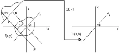
operations, being suitable for 3-D reconstruction. The interest for this method have been growing and Fourier based reconstruction methods have been developed which are able to compete with FBP method in cases of reconstructed image quality. We present here an implementation of a direct Fourier method for tomographic reconstruction, which is applicable to parallel beam x-ray image. Direct Fourier reconstruction uses the central-slice theorem to build a polar 2-D Fourier space from the 1-D transformed projections of the scanned objects then it is resampled into a Cartesian grid. Using inverse 2-D Fourier transform ,we get the reconstructed image. A sample application is presented and illustrated on the Sheep-Logan head phantom. We also show appropriate input zero padding and oversampling rates together with interpolation improves the interpolation of the 2-D image and is an efficient remedies to reduce artifacts. FRA is also known as Direct Fourier method or Fourier based method, which follow directly from the procedure explained above and are adapted to the discrete case.The central slice theorem defines that the Fourier transform in r of the radon projection at a given angle is equal to the axial slice at the same angle of the Fourier transform of the original volume:
,z
( )
r z(
rcos( ),
rsin( ))
p
k
F k
k
(4.1) [image:5.595.342.534.143.228.2]Where
p
,z( )
k
r is the 1-D Fourier transform in r of the projection acquired at angle θ and axial position z, and whereF u v
z( , )
is the in-plane 2D Fourier transform of the volume at axial position z. This relation is illustrated in Fig.4 shown below.Figure 4: Graphic visualisation of Fourier slice theorem statement
The most striking advantage of DFR (Direct Fourier
reconstruction) is its
O n
(
2log )
n
complexity imposed by the inverse 2D-FFT in step 3, whereas the more widely used filtered back projection (FBP) algorithm [image:5.595.327.536.410.524.2]usually performs in
O n
( )
3 . The major drawback of DFR lies in step 2 ie., inappropriate interpolation during the Cartesian re-sampling may cause image artifacts. There are some solutions to overcome this artifacts, which includes zero-padding of the input data and oversampling of the 2D Cartesian Fourier space.Fig. 5. Direct Fourier reconstruction algorithm overview
International Journal of Emerging Technology and Advanced Engineering
Website: www.ijetae.com (ISSN 2250-2459,ISO 9001:2008 Certified Journal, Volume 4, Issue 3, March 2014)
21
For each input line, data is shifted to the line ends around the origin and modulated to shift the DC to the center of the Fourier line. Once all projections of a slice have been transformed into Fourier space, the 2D-DFT is
re-sampled. The over sampling rate
n
g shortens the effective polar radius and then the angle is determined. The angle is then converted into a floating point index, used to linearly interpolate between the two adjacent angular samples. Thus radial interpolation is obtained. Note that, if the upper angular index overflows, the modified interval size ∆ applies, the angle is trimmed and the radius changes sign. After the inverse 2D-FFT, the requested region is collected from the edges of the image and demodulated to undo the FFT-shift.(a) (b)
(c) (d)
(e) (f)
(g)
Fig.6. Reconstruction using FRA (a) Original image, (b) Radon projection, (c) Slice in Fourier space,(d) Surface of Fourier Radon
on space, before interpolation, (e) Surface of Fourier Radon on space, before interpolation, (f) Interpolated Fourier space, (g)
Reconstructed image .
In summary, for each slice, each radial line of the sinogram is zero-padded, shifted and modulated before transforming it in 1D Fourier domain. The DC is shifted to the Nyquist frequency by Modulation, i.e. the line center in Fourier domain. The Cartesian 2D Fourier space is re-sampled from the polar data. After inverse 2D Fourier transformation, the image is unpadded and the image is recovered, results are illustrated in Fig.6. Overall we demonstrate that our algorithm produces good reconstruction quality whenever projections are correctly sampled.
V. FOURIER RECONSTRUCTION METHOD FOR FAN -BEAM PROJECTIONS
Unfortunately, since Fourier slice method applies just to parallel projections, the above described FRA don’t match the case of fan-beam geometry. There are two possible way to apply Fourier reconstruction method to Fan-beam projections. The first way includes a pre-reconstruction step called rebinning, which will be described below and allow to obtain parallel proj-ections from fan-beam projection data set by interpolation. Once obtained a full set of parallel projection, then any direct Fourier method can be simply applied be applied. The second way is to develop a Fourier reconstruction method directly to Fan-beam data set. We will describe a FRA to be applied directly to the fan-beam projections, without any rebinning and interpolation process, which means that we have developed based on the NUFFT(Non Uniform Fast Fourier Transform).
A. Rebinning
Rebinning is a well known interpolation process that has been used in the first fan-beam CT scanners until the development of reconstruction methods dedicated to that geometry. Since interpolation is performed in the projection domain, it is not critical operation like it is in the Fourier domain and can even be performed linearly without introducing noticeable error. Comparing equation (1.1) and (1.3), we see parameters of a ray in the parallel geometry are related to the parameters of the corresponding ray in the fan-beam geometry by the simple equations:
(5.1)arcsin
s
r
(5.2)International Journal of Emerging Technology and Advanced Engineering
Website: www.ijetae.com (ISSN 2250-2459,ISO 9001:2008 Certified Journal, Volume 4, Issue 3, March 2014)
22
It’s interesting to notice that to a line of sonogram samples corresponds a line of points slanted
45
0 in the fan-beam projections space (Fig.7), has to be pointed out that in order to obtain a complete sinogram for[ ,
]
, at least fan-beam projections with[ , ]
2 2
has to be knownFig.7. Rebinning process: dots represent the desired sonogram sample points and the corresponding interpolated points in the
divergent projections.
B. NUFFT based Direct Fourier method for fan-beam projections
Given a divergent projection data set, we can reorganize the samples in classes based on the inclinations θ= β + γ of the corresponding projections ray. This can be done by dividing the interval [0,π], in a number N of sub-interval equal to the desired number of parallel projections and taking as a parallel projection
j=1….N, the set of samples with θ in the th
j
sub interval. Since such a projection will contain non-uniformly distributed samples, to each sample in a projection will be associated the value of the parameter sof the corresponding projection ray. Applying 1-D NUFFT to each of these sample set we can obtain samples on the polar grid in the 2-D Fourier space and the algorithm can follow the same way like in the case of parallel projections. The following step shows our implementation method: 1) filter of the fan-beam projection with a Shepp-Logan window in Fourier space, 2) apply zero padding to the projection, 3) reorganization of the divergent sample set in parallel projection sample set, 4) Samples of a conventional oversampled polar grid is obtained from Fourier space by a 1-D NUFFT, 5) applied 2-D NUFFT to the polar samples to obtain reconstructed image from fan-beam projections. This method is computationally expensive due to the sample reorganization step, however, the quality of the reconstructed image is similar to the one obtained from parallel projections.
VI. CONCLUSION
In this paper we demonstrate the applicability of Fourier Reconstruction Algorithm (FRA) for the reconstruction of a 2-D object from its projection. Numerical results for reconstruction using FRA are presented. We also shown that the FRA can be us-ed for reconstruction from fan-beam projections. We then provide extensive results based on the standard Shepp-Logan phantom image. We also discuss the various reconstruction parameters and show their impacts on the outcome of recons-truction. The results have been analysed and showing that Fourier reconstruction algorithm are a valid alternative to the commonly used FBP algorithm with a remarkable reduction in complexity and computation time, with little or no added distortion. CT reconstruction using FRA can also be suitable for 3-D reconstruction.
REFERENCES
[1] Amir Averbuch, Ilya Sedelnikov and Y. Shkolnisky “CT Reconstruction From Parallel and Fan-Beam Projections by a 2D-Discrete Radon Transform”, vol. 21, no. 2, Feb 2012.
[2] S. R. Deans, The Radon Transform and Some of Its Applications. New York: Wiley, 1983.
[3] F. Natterer, The Mathematics of Computerized Tomography. New York: Wiley, 1986.
[4] A. Kak and M. Slaney, Principles of Computerized Tomographic Imaging. New York: IEEE Press, 1988.
[5] A. Averbuch, R. R. Coifman, D. L. Donoho, M. Israeli, and Y. Shkolnisky, “A framework for discrete integral transformations I– the pseudo-polar Fourier transform,” SIAM J. Sci. Comput., vol. 30, no. 2, pp. 764–784, Feb. 2008.
[6] A. Averbuch, R. R. Coifman, D. L. Donoho, M. Israeli, Y. Shkolnisky, and I. Sedelnikov, “A framework for discrete integral transformations II–the 2D discrete Radon transform,” SIAM J. Sci. Comput., vol. 30, no. 2, pp. 785–803, 2008.
[7] A. Brandt, J. Mann, M. Brodski, and M. Galun, “A fast and accurate multilevel inversion of the Radon transform,” SIAM J. Appl. Math., vol. 60, no. 2, pp. 437–462, 2000.
[8] S. Basu and Y. Bresler, “
O N
(
2log
2N
)
filtered backprojection reconstruction algorithm for tomography,”IEEE Trans. Image Process., vol. 9, no. 10, pp. 1760–1773, Oct. 2000. [9] S. Basu and Y. Bresler, “Error analysis and performanceoptimization of fast hier-archical backprojection algorithms ,”IEEE Trans. Image Process., vol. 10, no. 7, pp. 1103–1117, Jul. 2001.
[10] S. Basu and Y. Bresler, “Fast hierarchical backprojection method for imaging,” U.S. Patent 6 282 257, Aug. 28 2001.
[11] J. Miao, F. Förster, and O. Levi, “Equally sloped tomography with oversampling reconstruction,” Phys. Rev. B, vol. 72, no. 5, pp. 052 103- 1–052 103-4, Aug. 2005.
International Journal of Emerging Technology and Advanced Engineering
Website: www.ijetae.com (ISSN 2250-2459,ISO 9001:2008 Certified Journal, Volume 4, Issue 3, March 2014)
23
[13] B. P. Fahimian, Y. Mao, P. Cloetens, and J. Miao, “Low-dose X-ray phase-contrast and absorption CT using equally sloped tomography,” Phys. Med. Biol., vol. 55, no. 18, pp. 5383–5400, Sep. 2010.
[14] H. Schomberg and J. Timmer, “The gridding method for image reconstruction by Fourier transformation,” IEEE Trans. Med. Imag., vol. 14, no. 3, pp. 596–607, Sep. 1995.
[15] F. Matus and J. Flusser, “Image representation via a finite Radon transf-orm,”IEEE Trans. Pattern Anal. Mach. Intell., vol. 15, no. 10, pp. 996–1006, Oct. 1993.
[16] K. Fourmount, “Non-equispaced fast Fourier transform with applications to tomography”, pre-print , 2000.
[17] D. Gottlieb, B. Gustafsson and P. Forssen. On the Direct Fourier Method for Computer Tomography. IEEE Transacti-ons on Medical Imaging,19(3):223–232, March 2000.