Experimental and numerical study of buoyancy
driven flow within a bottom heated vertical
concentric cylindrical enclosure
Asif Hussain Malik1*, Shahab Khushnood1, Ajmal Shah2
1Department of Mechanical Engineering, University of Engineering and Technology, Taxila, Pakistan; *Corresponding Author: [email protected]
2Department of Mechanical Engineering, Pakistan Institute of Engineering and Applied Sciences, Islamabad, Pakistan
Received 28 February 2013; revised 1 April 2013; accepted 8 April 2013
Copyright © 2013 Asif Hussain Malik et al. This is an open access article distributed under the Creative Commons Attribution Li-cense, which permits unrestricted use, distribution, and reproduction in any medium, provided the original work is properly cited.
ABSTRACT
The study of buoyancy driven flow within bot- tom-heated vertical concentric cylindrical en- closure was important with respect to the proc- esses in chemical and nuclear industries. In this research paper, experimental and numerical stu- dy of the axial temperature gradient and the heat transfer mechanism within the enclosure were performed. The numerical simulations were vali- dated by comparing the numerical results with experimentally measured axial temperature. The numerical results of the streamlines within the enclosure depicted the real picture of the buoy- ancy effects. Eighteen different experiments were performed by using inner cylinder of different materials and outer cylinder of different diame-ters within the bottom disc temperature range of 353 - 433 K. The CFD simulations were per- formed to study the buoyancy effects within the enclosure. At the bottom disc with temperature up to 393 K, the streamlines within the inner cylinder were almost the same for both con- figurations being independent of outer cylinder diameter, while at 433 K streamlines within the inner cylinders varied. With larger diameter outer cylinder configuration, the buoyancy effects in the outer annulus were stronger as compared to smaller one.
Keywords:Experimental; Numerical Study;
Buoyancy Driven Flow; Cylindrical Enclosure; Materials; Temperature
1. INTRODUCTION
The buoyancy flow in the cylindrical enclosures has
been studied in the last couple of decades. Different pa- rameters of interest have been investigated to dig out different hidden precious pearls out of the ocean of knowl- edge, but still leaving thrust of searching the new one. It has many engineering applications in the solar collectors, centrifuge machines, heat exchangers, materials proc- essing, storage tanks, furnace designs and nuclear de- signs, etc.
The past researchers have conducted numerical study of buoyancy flow through different enclosures. The past authors [1-4] have numerically investigated the buoyancy effects within the cylindrical enclosures with thermo- physical fluid properties assumed to be constant except density variation which varies according to Boussinesq approximation. Lemembre et al. have numerically inves-tigated the two-dimensional laminar natural convection heat transfer in cylindrical enclosures of heated lateral walls at uniform heat flux and cooled at the same heat flux at the top surface by insulating the bottom surface [5]. The convection heat transfer was enhanced with the increase of aspect ratio and Rayleigh number. Chen et al. have numerically presented the two-dimensional steady- state laminar natural convection in the rectangular en- closures [6]. The flow and heat transfer in the enclosure were strongly affected by an asymmetric specification of the side wall temperatures. The asymmetry has induced a disproportionately higher increase in the Nusselt number of the hotter side wall relative to the decrease in Nusselt number of the colder wall.
experimental and numerical study of steady natural con- vection in two-dimensionalNewtonian and incompressi- ble fluid-filled enclosures. They have concluded that heat conduction has reduced the average temperature differ- ence across the enclosure, produced partial stabilization of the flow and decreased natural convection heat trans- fer. The heat transfer and fluid flow leading to thermal stratification inside the enclosure were also studied. Bohn et al. have experimentally investigated the heat transfer between parallel and perpendicular vertical walls in a three-dimensional water-filled cubical enclosure with an adiabatic top and bottom and isothermal sides and dis- cussed many aspects of natural convection flow [10].
Glakpe et al. have numerically investigated the lami-nar, three-dimensional natural convection in the air-filled vertical annular space formed by a square rod enclosed within a cylinder strongly affected by the Rayleigh num- ber [11]. They have studied the effects of thermal radia- tion exchange between walls of an enclosure. Liaqat et al. have numericallyanalyzed laminar two-dimensional con- jugate natural convection in an enclosure [12]. Their re- search has shown a significant change in the buoyancy flow parameters as compared to convectional investiga- tions. Kuznetsov [13] has numerically investigated the two-dimensional conjugate convective-conductive heat transfer in a rectangular enclosure due to the local heat and contaminant sources and convective-radiative heat exchange with environment. The research work on the experimental study of conjugate heat transfer within a bottom heated vertical concentric cylindrical enclosure have been performed in Malik et al. [14].
In this research paper, the buoyancy effects within the vertical concentric cylindrical enclosure have been stud- ied experimentally and numerically. The experimental results were measured at selected discrete points within the enclosure. Therefore, 2-D numerical simulations were performed using Fluent code to have a better under- standing of the heat transfer and buoyancy effect, espe- cially within the inner cylinder. The CFD results were validated using the experimental results of temperature along the wall of inner cylinder, already published in [14] and the new experimental axial temperature data along the axis of the enclosure. The numerical simulation re- sults of streamlines of the each experiment were obtained to study buoyancy forces behavior due to change in the temperature of the bottom disc as well as the effects of thermal conductivities of the inner cylinder materials.
2. EXPERIMENTAL SETUP
In this research paper the CFD analysis of experimen- tal work of the enclosure is performed to study the mate- rial effects of the disc and inner cylinder and diametric effects of the outer cylinder on the enclosure within the
temperature range of 353 - 433. The experimental model used in this research work includes two vertical concen- tric cylinders with the inner shorter than the outer one, an electric heater, foundation box, temperature sensors, tem- perature controller, data acquisition system and a com- puter. Eighteen experiments are performed by changing the bottom disc temperature, inner cylinder material and outer cylinder diameter. The top as well as the bottom of the enclosure, except the bottom disc, are insulated with a layer of ceramic wool placed between two sheets of Teflon. N-type thermocouple is mounted to the upper central location of the disc. In the experiment 82 PT-100 type thermocouples are used. The uncertainty in the reading of N-type thermocouple is estimated to be less than 1.5% and that of PT-100 sensors less than 1.1%, including the effect of the scatter of observed experi-mental data as given in detail in Malik et al. [14].
3. MATHEMATICAL FORMULATION
Mathematical formulation of the buoyancy flow ef- fects in the fluid-filled enclosures includes the governing equations of conservation of mass, momentum and en- ergy to solve the flow domain. To deal with the conduc- tion within the solids and radiations from hot surfaces their mathematical formulation must be added. In the subsequent articles a brief introduction of the equations necessary for solving conjugate heat transfer processes is given.
The Navier-Stokes governing equations in their dif-ferential form in 2-D cylindrical coordinate system (r, z) can be written as below:
rz r
v
v v
t z r r
Sm (1)
1 1
1 2 2
3 1
z z z r z
z
z r
z
v r v v r v
t r z r r
v
p r v
z r z z
v v
r F
r r r z
v (2)
22
1 1
1
2
1 2 2
3 2
2 3
r z r
r z
r
r z
r
v r v v r v
t r z r r
v v
p
r
r r z z r
v
r v
r r r
v v v F r r r
r rv
(3)
2 . 3T
v v
(4)
eff j j eff h
j
E v E p
t
k T h J v S
(5)
These equations have been mentioned in detail in [15- 18].
Where, r = radial coordinate, z = axial coordinate, vr = radial velocity of the fluid, vz = axial velocity of the fluid,
ρ = density of fluid, Sm = mass source term within the differential volume, p = static pressure, τ = stress tensor, g = acceleration due to gravity, F = external body forces including other model-dependent source terms such as porous medium and user-defined sources, μ = dynamic viscosity, I = unit tensor, keff = effective conductivity in- cluding the effect of turbulent thermal conductivity Jj = diffusion flux of species, and J. τeff = effective stress ten-sor, Sh = energy source term including radiation source, chemical reaction source etc.
The first three terms on the right side of Eq.5 give en- ergy transfer due to conduction, species diffusion and viscous dissipation, respectively. The buoyancy forces can be designated by the ratio of Grashof and Reynolds numbers as shown below:
2 2
Re
Gr g TL
v
(6)
There are strong buoyancy effects on the fluid flow when the above number approaches or exceeds unity. The strength of the buoyancy-induced flow in the pure natural convection is measured by the Rayleigh number;
3
g TL
Ra
(7)
where, β = coefficient of thermal expansion and α = thermal diffusivity.
p k
c
(8)
A buoyancy-induced laminar flow is assumed at Ra < 108 and transition from laminar to turbulence is assumed in the range of 108 < Ra < 1010.
According to the Boussinesq approximation the den-sity of the fluid is given by:
1
o T T
o
T
(9)
where, ρo = constant density of the fluid in the closed
domain, To = operating temperature and β = coefficient
of thermal expansion.
Fourth term of the energy equation (Eq.5) (Sh) also
includes the heat source due to radiation. Rosseland ra- diation model is used which is faster and requires less memory as compared to other radiation models and deals with axisymmetric geometries and contains the effect of scattering. The radiative heat flux equation, the equation becomes;
2 3
16
r
q n T (10) Both the specific radiative (qr) and specific conduction heat fluxes (qc) have the same form, therefore, these can be written as,
c r r
q q q k k T (11) where, k is the thermal conductivity, kr is the radiative conductivity.
3.1. Boundary Conditions
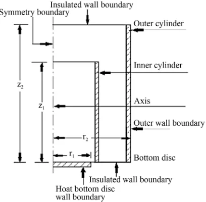
[image:3.595.101.287.83.178.2] [image:3.595.322.526.510.710.2]In this research work the experimental model used is the vertical concentric cylindrical enclosure as shown in Figure 1. The mathematical formulation of these bound- ary conditions is given below.
3.1.1. Bottom Disc Wall Boundary
Heat source is applied at the bottom of the disc of ra-dius, r1. The temperatures are specified for different ex-periments at z = 0 and known. Its boundary conditions are;
At z0; 0 r r1;
v v
T is known; r z 0 (No slip condition). 3.1.2. Bottom Insulated Wall Boundary
Bottom surface of enclosure is assumed to be insulated except bottom disc heated by the heat source. Its bound-ary conditions are:
At z0;r1 r 2;
0
vrvz (No slip condition); r for an adiabatic wall.
0
in out q q
3.1.3. Side Wall Boundary
Natural convection heat transfer coefficient ho is taken as a boundary of enclosure. Heat entering from the hot bottom disc after passing through the walls of inner cyl- inder comes out of the wall of outer cylinder of enclosure. Its boundary conditions are: at r r 2; 0zz2.
3.1.4. Symmetry Boundary
In 2-D axisymmetric geometry the axis is used as a symmetry boundary and half of the geometry is taken for the analysis as shown in Figure 1 as used by the past researchers [19-21]. Its boundary conditions are:
at r0; 0zz2; 0; z 0; r 0
v v
T
r r r
.
3.1.5. Top Insulated Wall Boundary
Top wall of enclosure is taken as insulated or adiabatic one. Its boundary conditions are;
At (No slip condition);
. 2,; 0 2; zz r r
0
out
q q vr vz 0
in
4. NUMERICAL SIMULATIONS
In this research paper the experimental and numerical study of the heat transfer and buoyancy driven flow along axis of the enclosure is studied. The numerical simulations of inner cylinder of the enclosure are per-formed validating the experimental results of Malik et al. [14] the chemical processes take place within the inner cylinder of the enclosure and main concentration of the chemical reactions is along axis of the enclosure. The numerical simulations are validated by comparing with experimental results and presented streamlines of the each experiment clearly depicting the real picture of the of the enclosure showing buoyancy forces due to change in the temperature range of the bottom disc.
This research study provided a thorough insight of the buoyancy flow and its effects due to the change of inner cylinder wall material in the enclosure and outer cylinder diameter. FLUENT 6.3 software is used to study the buoyancy forces within the enclosure, compare and vali- date numerical results with the experimental ones and get insight of the flow and heat transfer mechanism within the enclosure as used by the past researchers [9,19,22].
Two-dimensional steady state analysis is carried out. The Rosseland radiation model is selected. Air is treated as a stationary, incompressible and laminar fluid. The FLUENT have used the pressure-based solver. The sec- ond order scheme is used for pressure, while the second order upwind discretization schemes are used for mo-
mentum and energy [23]. The flow and energy equations are solved by the FLUENT [15] and the Green-Gauss cell-based gradient scheme is selected. Boussinesq ap- proximation is used. In order to solve the pressure-ve- locity coupling SIMPLE algorithm is used [1,4,24-28]. The convergence criteria are different for different cases [29-31]. Iterations took place till the convergence is achieved in the range of 765 - 4968 iterations. Eighteen experiments are performed at the specific temperatures of 353, 393 and 433 K on the upper central location of bottom discs. The mesh selected is square and total cells of both configurations (O1 and O2) are 213,960 and 247,400 respectively.
4.1. Geometry and Meshing
In this research work the geometry considered for analysis is a two-dimensional axisymmetric one due to which the axis is used as a symmetry boundary. The half of the geometry is taken for the analysis due to its axi-symmetric geometry [19-21]. Gambit 2.3.16 is used as a preprocessor to construct the geometry and mesh.
The geometry is generated and meshed in the Gambit software as shown in the Figure 2. Square mesh is used
to mesh the geometry. The grid points along the axis of the geometry are 1541 while at its top and bottom are 211. Due to change in diameters of the radial grid points are 139 and 151 for outer cylinders, O1 and O2 respec- tively.
The buoyancy flow about the geometry axis is as-sumed to be symmetric. 2-D axisymmetric simulations are carried out. The bottom disc of the enclosure being simulated has been shown in the Figure 1. Top and bot- tom walls of the enclosure except the bottom disc are assumed to be adiabatic with no heat flux and no heat generation with no slip condition on the enclosure walls. The walls within the enclosure are thermally coupled. The convection heat transfer coefficient, h is selected as a boundary condition at the outer surface of the outer vertical cylinder by hit and trial method.
The inner and outer cylinders walls are considered as conducting walls. The user defined function has incur- porated the experimental temperature results of bottom disc and coupled with the FLUENT [15]. The three inner cylinders of aluminum, mild-steel and stainless-steel having similar dimensions are used in different configu- rations.
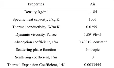
[image:5.595.57.288.497.635.2]The outer surface of the simulated enclosure is far away from heat source, it was assumed that the pressure and temperature at the outer surface of the enclosure are equal to the ambient to allow free movement across this surface. There is an ambient temperature at the top of the vertical enclosure, so the enclosure was assumed as an infinite enclosure. The properties of fluid and materials used in these simulations are given in the Tables 1 and 2 respectively as taken from research paper [32].
Table 1. Properties of Fluid (air).
Properties Air Density, kg/m3 1.184
Specific heat capacity, J/kg·K 1007 Thermal conductivity, W/m·K 0.02551
Dynamic viscosity, Pa·sec 1.8949E−5 Absorption coefficient, 1/m 0.49919, constant
[image:5.595.58.286.666.737.2]Scattering phase function Isotropic Scattering coefficient, 1/m 0 Thermal Expansion Coefficient, 1/K 0.0033445
Table 2. Properties of Materials.
Properties Aluminum Mild Steel Stainless Steel
Density, kg/m3 2739 7833 8238
Specific heat capacity, J/kg·K 896 502 468 Thermal conductivity, W/m·K 222 45.3 13.4
4.2. Grid Independence Study
The grid independence study is carried out by taking the grids of cell sizes 2 mm, 1.5 mm, 1mm and 0.5 mm as shown in the Table3. There is a prominent percentage error of cell sizes 2 mm, 1.5 mm and 1mm, while cell sizes 1mm and 0.5 mm have almost the same percentage error with the experimental results of the axis of the en-closure Malik et al. [14]. Therefore, cell size of 1 mm is taken while meshing the enclosure under research. The numerical simulations results are compared with the ex-perimental results.
5. RESULTS AND DISCUSSION
Before discussing numerical results an effort was made to validate the numerical simulations. The experimental data of eighteen different experiments was used to vali- date the numerical results. Three different inner cylinders made of aluminum, mild steel and stainless steel and two outer cylinder diameters have been used in the experi- ments. The comparison between experimental and nu- merical simulation results of temperature within enclo- sure configurations with inner cylinders of aluminum, mild steel and stainless steel at different bottom disc cen- tral temperatures (353, 393 and 433 K) is shown in Fig- ure 3. The positive and negative errors of numerical si- mulation results with the experimental ones are 1% and 1.3% respectively. This shows that numerical simulation results are in best agreement with experimental ones.
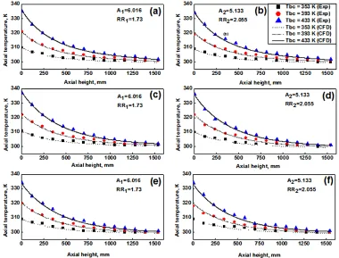
5.1. Temperature Profile along the Enclosure Axis
The heat transfer mechanism within the inner cylinder has a strong effect on the process of segregation of chemi- cals taking place here. The temperature behavior at the wall of inner cylinder using experimental data for the same geometry has been studied previously by Malik et al. [14], however, the experimental temperature data along the axis of the inner cylinder and the numerical results of streamlines within the enclosure have been presented in this paper to study the buoyancy effects. The comparison of experimental and numerical axial temperature distri-bution along the axis of vertical concentric cylindrical enclosure under different operating conditions is shown in Figure 4. The experimental results of axial tempera-ture match closely with the numerical simulation results and thus validating the numerical simulations. The aspect ratio and radius ratio of the enclosure geometry with outer cylinder O1 are 6.016 and 1.73, while with outer cylinder O2 these values are 5.133 and 2.055 respec-tively.
Table 3. Grid independence study.
[image:6.595.60.544.105.438.2]Grid of cell size = 0.5 mm Grid of cell size = 1 mm Grid of cell size = 1.5 mm Grid of cell size = 2 mm Number of cells 855,840 213,960 96,135 54,260 Percentage error 1.91 1.94 2.9 4.2
Figure 3. Comparison of experimental and CFD results of enclosure with inner cylinders of aluminum, mild steel and stainless steel.
[image:6.595.107.487.421.710.2]Figures 4(c)-(f) show that the axial temperature distribu- tion using mild steel and stainless steel inner cylinders is a function of the outer cylinder diameter especially at higher temperatures of the bottom disc. This response might be due to high thermal conductivity of aluminum as compared to mild steel and stainless steel.
5.2. Temperature Profile along the Inner Cylinder
As mentioned before the experimental temperature data along the wall of inner cylinder has been published previously [14], however, this data is used in this work to validate the numerical results. The comparison of ex- perimental and numerical axial temperature distribution along the wall of inner cylinder under different operating conditions is shown in Figure 5.
It is observed in Figures 5(a) and (b) that using inner cylinder of aluminum material, under different tempera-tures of the bottom disc and using two different outer cylinders O1 and O2. Figures 5(c)-(f) show the same re- sults using inner cylinders of mild steel and stainless steel respectively. It is observed in Figures 5(a) and (b) that using inner cylinder of aluminum the axial tempera- ture distribution along the inner cylinder is independent of the outer cylinder diameter, while using inner cylin- ders of mild steel and stainless steel (Figures 5(c)-(f))
the axial temperature along the inner cylinder depends on the diameter of outer cylinder.
The close agreement between the experimental and numerical results of axial temperature along inner cylin-der supports the numerical simulation of vertical concen-tric cylindrical enclosure. By comparing the Figures 4 and 5 along the axis and the inner surface of inner cylin-der of the enclosure respectively it is observed that the temperatures along the axis are slightly higher than along the wall of the inner cylinder at the same axial location. This temperature gradient boosts the buoyancy effect and therefore helps the segregation of chemicals as well as transfer of heat out of the inner cylinder.
5.3. Buoyancy Effect in the Enclosure
[image:7.595.118.483.419.703.2]When an object is partially or fully immersed in a flu- id the upward force exerted on the object is called buoy- ancy force. The value of this buoyancy force is equal to the weight of the fluid displaced by the object. The fluid density varies with temperature by the addition of heat to a fluid and flow is induced by the gravitational force acting on the density variations called natural convection flows. The streamlines clearly depict the buoyancy ef- fects in the enclosure with the change of inner cylinder material and outer cylinder diameter at bottom disc tem- perature range of 353 - 433 K.
5.3.1. Contours of Streamlines at 353 K
The contours of streamlines are obtained from nu- merical simulations for the enclosure configurations O1 and O2 at bottom disc central temperature of 353 K and are shown in Figure 6. Figures 6(a) and (b) show streamlines for two configurations (O1, O2) of aluminum inner cylinder, while Figures 6(c)-(f) show the corre- sponding results for mild steel and stainless steel inner cylinders.
It was observed in Figures 6(a) and (b) that the streamlines within the inner cylinder are same for both configurations (O1, O2) of aluminum inner cylinder. The same behavior was observed in case of mild steel (Fig- ures 6(c) and (d)) and stainless steel inner cylinders (Figures 6(e) and (f)). However, the streamlines in the inner cylinder of Figures 6(a) and (b) show weak buoy- ancy effects as compared to Figures 6(c)-(f). Another important observation made regarding Figure 6 is that the buoyancy effects are stronger in the outer annulus with outer cylinder configuration O2 as compared to con- figuration O1 for all three inner cylinders used. The buoyancy effects in the outer annulus are stronger in case of aluminum inner cylinder as compared to mild steel and stainless steel for the same outer configuration. The same behavior was observed in case of mild steel inner cylinder as compared to stainless steel.
At the bottom disc central temperature of 353 K the quantity of heat transfer added to the enclosure is small
and therefore the effect of outer cylinder configuration on the heat transfer from the inner cylinder to the outer annulus region is negligible. However, due to difference of thermal conductivity buoyancy effects are relatively weak in Figures 6(a) and (b) as compared to Figures 6(c)-(f). With outer cylinder configuration O2 the buoy- ancy effects are stronger due to increase in volume as compared to configuration O1 for three inner cylinders used. In the outer annulus the buoyancy effects are stronger while using inner cylinder of aluminum as compared to other inner cylinders due to its high thermal conductivity.
5.3.2. Contours of Streamlines at 393 K
[image:8.595.57.539.433.708.2]The contours of streamlines are obtained from nu-merical simulations for the enclosure configurations O1 and O2 at bottom disc central temperature of 393 K and are shown in Figure 7. Figures 7(a) and (b) show streamlines for two configurations (O1, O2) of aluminum inner cylinder. Similarly Figures 7(c)-(f) show the cor- responding results for mild steel and stainless steel inner cylinders. It is observed in Figures 7(a) and (b) that the streamlines within the inner cylinder are same for both configurations (O1, O2) of aluminum inner cylinder. The same behavior is observed in case of mild steel and stainless steel inner cylinders (Figures 7(c)-(f)), but the streamlines in the inner cylinder of Figures 7(a) and (b) show weak buoyancy effects as compared to Figures 7 (c)-(f).
Figure 6. Streamlines of enclosure for configuration O1 (a) aluminum inner cylinder, (c). mild steel inner cylinder, (e) stainless steel
Figure 7. Streamlines of enclosure for configuration O1 (a) aluminum inner cylinder, (c). mild steel inner cylinder, (e) stainless steel
inner cylinder, for configuration O2 (b) aluminum inner cylinder, mild steel inner cylinder, (f), stainless steel inner cylinder at 393 K.
The buoyancy effects are stronger in the outer annulus with outer cylinder configuration O2 as compared to con- figuration O1 for all three inner cylinders used. The buoy- ancy effects in the outer annulus are stronger in case of aluminum inner cylinder as compared to mild steel and stainless steel for the same outer configuration. The same behavior is observed in case of mild steel inner cylinder as compared to stainless steel.
Like 353 K at the bottom disc central temperature of 393 K the quantity of heat added to the enclosure is small due to which the heat transfer on outer annulus region with the increase of outer cylinder diameter is negligible. Contours of streamlines are at 433 K.
However, due to difference of thermal conductivity buoyancy effects are relatively weak in Figures 7(a) and (b) as compared to Figures 7(c)-(f). With outer cylinder configuration O2 the buoyancy effects are stronger due to increase in volume as compared to configuration O1 for three inner cylinders used. In the outer annulus the buoyancy effects are stronger while using inner cylinder of aluminum as compared to other inner cylinders due to its high thermal conductivity.
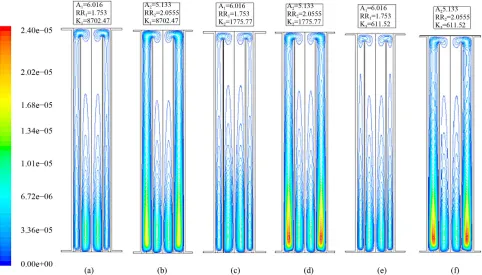
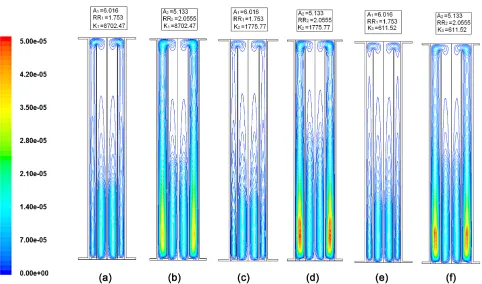
The contours of streamlines are obtained from nu-merical simulations for the enclosure configurations O1 and O2 at bottom disc central temperature of 433 K and are shown in Figure 8. Figures 8(a) and (b) show streamlines for two configurations (O1, O2) of aluminum inner cylinder, while Figures 8(c)-(f) show the
corre-sponding results for mild steel and stainless steel inner cylinders. It is observed in Figures 8(a) and (b) that at bottom disc temperature of 433 K the streamlines be-havior within the inner cylinder changes with outer cyl-inder configuration for aluminum inner cylcyl-inder. Simi-larly the same behavior is observed for mild steel and stainless steel inner cylinders (Figures 8(c)-(f)). The most remarkable observation made regarding Figure 8 is that the buoyancy effects are stronger in the outer annu-lus with configuration O2 as compared to configuration O1 for all three inner cylinders used. The buoyancy ef- fects in the outer annulus are stronger in case of alumi-num inner cylinder as compared to mild steel and stainless steel for the same outer configuration.
Figure 8. Streamlines of enclosure for configuration O1 (a) aluminum inner cylinder, (c) mild steel inner cylinder, (e) stainless steel
inner cylinder, for configuration O2 (b) aluminum inner cylinder, mild steel inner cylinder, (f) stainless steel inner cylinder at 433 K.
Figure 9. Streamlines of lower half of the enclosure for configuration O2 (a) aluminum inner cylinder, (b) mild steel inner cylinder, (c)
stainless steel inner cylinder at 433 K.
through the wall of the aluminum inner cylinder forming one axially dominant thermo-siphoning in the outer an-nulus as shown in the Figure 9(a). For the mild steel and
[image:10.595.61.537.396.660.2]the enclosure with the lower one as radially dominant and upper one as axially dominant as shown in the Fig- ures 9(b) and (c).
Due to high thermal conductivity of aluminum, the buoyancy effects within the inner cylinder are less and more heat is transferred through the wall of aluminum inner cylinder than mild steel and stainless steel ones forming one axially dominant thermo-siphoning in the outer annulus as shown in the Figure 9(a). While, due to low thermal conductivities of mild steel and stainless steel buoyancy effects are more and walls of the inner cylinders are at higher temperatures than the walls of the aluminum inner cylinder as shown in the Malik et al. [14]. Therefore, in their outer annuli there are two thermo- siphonings with the lower one as radially dominant and upper one as axially dominant as shown in the Figures 9(b) and (c).
In the outer annulus the buoyancy effects are stronger while using inner cylinder of aluminum as compared to other inner cylinders due to its high thermal conductivity. The stream lines in Figures 6-9 also suggest that due to high thermal conductivity of aluminum inner cylinder, the heat conduction in inner cylinder wall in the axial direction is high as compared to inner cylinders of mild steel and stainless steel. This behavior is more clearly visible in Figure 9, where due to low thermal conductiv-ity of mild steel and stainless steel double vortices are formed in the outer annulus region with outer cylinder configuration O2 (Figures 9(b) and (c)). Apart from the above discussion there are other numerous points which can be highlighted using the numerical simulation re- sults.
6. CONCLUSIONS
In this research paper, experimental and numerical study of the axial temperature gradient, buoyancy driven flow and the heat transfer mechanism within the enclosure were performed. The numerical simulations were vali- dated by comparing the numerical results with experi- mentally measured axial temperature. The numerical re- sults of the streamlines within the enclosure depicted the real picture of the buoyancy effects. Eighteen different experiments were performed in a controlled environment. The axial thermal behavior along the axis and inner cyl- inder of the enclosure were studied by varying bottom disc central temperature (353 - 433 K), inner cylinder material and outer cylinder diameter. The main focus of this study was given on the thermal behavior and buoy- ancy effects of the enclosure by using three inner cylin- ders of different materials and having large difference in their thermal conductivities. The numerical simulations were performed and validated by the experimental results. The heat transfer and buoyancy effects within the enclo- sure geometry were highlighted through streamlines
ob-tained from numerical simulations. As a result of these experiments and numerical simulations, following points were concluded;
1) The heat transfer in the enclosure with stainless steel inner cylinder was more sensitive to outer cylinder diameter as compared to mild steel. In this case, thermal conductivity and the outer cylinder diameter were both the controlling parameters for the heat transfer mecha- nism. Aluminum was non-sensitive to the outer cylinder diameters (O1, O2).
At the bottom disc temperature of 353 K and 393 K, the streamlines within the inner cylinder were almost same for both configurations (O1, O2) of three inner cyl- inders of aluminum, mild steel and stainless steel being independent of outer diameter used, but clear changes were being observed at 433 K.
2) With outer cylinder configuration O2 the buoyancy effects were stronger due to increase in volume as com- pared to configuration O1 for three inner cylinders used.
3) In the outer annulus, the buoyancy effects were stronger while using inner cylinder of aluminum as com- pared to other inner cylinders due to its high thermal conductivity.
One axially dominant thermo-siphoning was formed in the outer annulus due to high thermal conductivity of aluminum inner cylinder, while two thermo-siphonings were formed in the outer annuli with the lower one as radially dominant and upper one as axially dominant due to their low thermal conductivities of mild steel and stainless steel inner cylinders.
REFERENCES
[1] Sharma, A.K., Velusamy, K. and Balaji, C. (2008) Con- jugate transient natural convection in a cylindrical enclo-sure with internal volumetric heat generation. Annals of Nuclear Energy, 35, 1502-1514.
[2] Franke, M.E. and Hutson, K.E. (1984) Effects of corona discharge on free-convection heat transfer inside a verti- cal hollow cylinder. Journal of Heat Transfer, 106, 346- 351. doi:10.1115/1.3246679
[3] Roschina, N.A., Uvarov, A.V. and Osipov, A.I. (2005) Natural convection in an annulus between coaxial hori- zontal cylinders with internal heat generation. Interna- tional Journal of Heat and Mass Transfer, 48, 4518-4525. doi:10.1016/j.ijheatmasstransfer.2005.05.035
[4] Bairi, A. (2003) Transient natural 2D convection in a cylindrical cavity with the upper face cooled by thermoe-lectric peltier effect following an exponential law. Ap- plied Thermal Engineering, 23, 431-447.
[5] Lemembre, A. and Petit J.-P. (1998) Laminar natural con- vection in a laterally heated and upper cooled vertical cy- lindrical enclosure. International Journal of Heat and Mass Transfer, 41, 2437-2454.
doi:10.1016/S0017-9310(97)00367-0
dimensional, natural convection in rectangular enclosures with differently heated walls. Journal of Heat Transfer, Transactions of the ASME, 109, 400-406.
[7] Kee, R.J., Landram, C.S. and Miles, J.C. (1976) Natural convection of a heat generating fluid within closed verti- cal cylinders and spheres. Journal of Heat Transfer, Transactions of the ASME, 98, 55-61.
[8] Kim, D.M. and Viskanta, R. (1985) Effect of wall heat conduction on natural convection heat transfer in a square enclosure. Journal of Heat Transfer, Transactions of the ASME, 107, 139-146.
[9] Vargas, M., Sierra, F.Z., Ramos, E. and Avramenko, A.A. (2002) Steady natural convection in a cylindrical cavity. International Communication of Heat and Mass Transfer, 29, 213-221. doi:10.1016/S0735-1933(02)00312-3 [10] Bohn, M.S. and Anderson, R. (1986) Temperature and
heat flux distribution in a natural convection enclosure flow. Journal of Heat Transfer, Transactions of the ASME, 108, 471-476.
[11] Glakpe, E.K., Watkins, C.B. and Kurien, B.J. (1986) Ef- fect of radiation and specified heat flux on natural con- vection in a vertical region with a rectangular inner boundary. 4th Joint Thermodynamics and Heat Transfer Conferences on AIAA and ASME, Boston, 2-4 June 1986, 10 pages.
[12] Liaqat, A. and Baytas, A.C. (2001) Conjugate natural convection in a square enclosure containing volumetric sources. International Journal of Heat and Mass Transfer, 44, 3273-3280.
[13] Kuznetsov, C.V. and Sheremet, M.A. (2009) Conjugate heat transfer in an enclosure under the condition of inter-nal mass transfer and in the presence of the local heat source. International Journal of Heat and Mass Transfer, 52, 1-8. doi:10.1016/j.ijheatmasstransfer.2008.06.034 [14] Malik, A.H., et al. (2012) Experimental study of conju-
gate heat transfer within a bottom heated vertical concen- tric cylindrical enclosure. International Journal of Heat and Mass Transfer, 55, 1154-1163.
doi:10.1016/j.ijheatmasstransfer.2011.09.055 [15] Fluent (2006) Fluent 6.3 user’s guide. Fluent Inc. [16] Rolf, H., Sabersky, A.J.A. and Hauptmann, E.G. (1971)
Fluid flow: A first course in fluid mechanics. Macmillan Publishing Co., Inc., New York.
[17] White, F.M. (1986) Fluid mechanics. 2nd Edition, Mc- Graw Hill Book Company, Blacklick, 732 pages. [18] Daugherty, R.L., Franzini, J.B. and Finnemore, E.J. (1996)
Fluid mechanics with engineering applications. McGraw Hill Book Company, Singapore.
[19] Wrobel, W., Fornalik-Wajs, E. and Szmyd, J.S. (2010) Experimental and numerical analysis of thermo-magnetic convection in a vertical annular enclosure. International Journal of Heat and Fluid Flow, 31, 1019-1031.
[20] Lin, W. and Armfield, S.W. (2001) Natural convection cooling of rectangular and cylindrical containers. Interna- tional Journal of Heat and Fluid Flow, 22, 72-81. doi:10.1016/S0142-727X(00)00065-5
[21] Papanicolaou, E. and Belessiotis, V. (2002) Transient na- tural convection in a cylindrical enclosure at high rayl- eigh numbers. International Journal of Heat and Mass Transfer, 45, 1425-1444.
doi:10.1016/S0017-9310(01)00258-7
[22] Corvaro, F. and Massimo, P. (2009) The natural convec- tive heat transfer in a partially divided enclosure: A study on the influence of the source position. Journal of Ther- modynamics, 1-11. doi:10.1155/2009/792370
[23] Kuznetsov, Geniy V. and Sheremet, Mikhail A. (2011) Conjugate natural convection in an enclosure with a heat source of constant heat transfer rate. International Jour- nal of Heat and Mass Transfer, 54, 260-268.
[24] Aminossadati, S.M. and Ghasemi, B. (2005) The effects of orientation of an inclined enclosure on laminar natural convection. Heat and Technology, 23, 43-49.
[25] Nazrul, I., Gaitonde, U.N. and Sharma, G.K. (2001) Mix- ed convection heat transfer in the entrance region of hori- zontal annuli. International Journal of Heat and Mass Transfer, 44, 2107-2120.
doi:10.1016/S0017-9310(00)00223-4
[26] Sezai, I. and Mohamad, A.A. (2000) Natural convection heat transfer from a discrete heat source on the bottom of a horizontal enclosure. International Journal of Heat and Mass Transfer, 43, 2257-2266.
[27] Mazumder, S. (2007) On the use of the fully compressible navier stokes equations for the steady-state solution of natural convection problems in closed cavities. Journal of Heat Transfer, Transactions of the ASME, 129, 387-390. [28] Bouali, H., Mezrhab, A., Amouli, H. and Bouzidi, M.
(2006) Radiation-natural convection heat transfer in an inclined rectangular enclosure. International Journal of Thermal Sciences, 45, 553-566.
[29] Yu, E. and Joshi, Y.K. (1999) Heat transfer in discretely heated side-vented compact enclosures by combined con- duction, natural convection and radiation. Journal of Heat Transfer, Transactions of the ASME, 121, 1002-1010. [30] Chang, T.S. and Tsay, Y.L. (2001) Natural convection
heat transfer in an enclosure with a heated background step. International Journal of Heat and Mass Transfer, 44, 3963-3971. doi:10.1016/S0017-9310(01)00035-7
[31] Zhao, F.-Y., Liu, D. and Tang, G.-F. (2008) Natural con-vection in an enclosure with localized heating and salting from below. International Journal of Heat and Mass Transfer, 51, 2889-2904.