HP 9800 Computers
98770 CE Handbook
Part No. 98770-90039 E1083 Requires Binder No. 9282-0683
~~ PACKARD
98770 CE Handbook
f: Copyright t 982, 1983, Hewle1t-Packard Company
This documen1 contains proprietary information which is protected by copyright. All rights are reserved. No part of this document may be photocopied, reproduced or translated to another language without the prior wri1ten consent of Hewle1t-Packard Company. The information contained in this document is subject to change without notice
Restricted Rights Legend
Use, duplication, or disclosure by the Government is subject to restrictions as set forth in paragraph (b)(3)(B) of the Rights in Technical Data and Software clause in DAR 7-104.9(a)
Hewlett-Packard Company
( hilptpr l
')'611U LIIUHillllH'lltdllllstdlldtlOII 1';\1
( hdpl"1 ,~
Q",77() ( IH11Jq11ldlH1l1
( h,'!'1<'r I ')S770 1 }(,1I1Jl, ~l)(H)tlll~
( IIdpl!'1 1 q~/ffl I), H",,, ... Tl,
( hil(lt!'f h
()8770 \dJlI~tlll!'llh
( h,'1)(( 17
'1'6770 i'l'lIph"r,lb
Chdplel S l}S770 Hepldl PIII('111 Prlft<,
( hrlptPI 9 98770 Dld~lfdm.,
Chdptl'f 10 IJI'!770 Hl'tefPIH P
Ii
Printing History
New editions of this manual will incorporate all material updated since the previous edition. Update packages may be issued between editions and contain replacement and additional pages to be merged into the manual by the user. Each updated page will be indicated by a revision date at the bottom of the page. A vertical bar in the margin indicates the changes on each page. Note that pages which are rearranged due to changes on a previous page are not considered revised.
The manual printing date and part number indicate its current edition. The printing date changes when a new edition is printed. (Minor corrections and updates which are incorporated at reprint do not cause the date to change.) The manual part number changes when extensive technical changes are incorporated.
First Edition ... October 1982 Second Edition ... October 1983
Warranty Statement
Hewlett-Packard products are warranted against defects in materials and workmanship. For Hewlett-Packard Fort Collins Systems Division products sold in the USA. and Canada, this warranty applies for ninety (90) days from the date of delivery.' Hewlett-Packard will. at its option, repair or replace equipment which proves to be defective during the warranty period. This warranty includes labor, parts, and surface travel costs, If any Equipment returned to Hewlett-Packard for repair must be shipped freight prepaid. Repairs necessitated by misuse of the equipment. or by hardware, software, or interfacing not provided by Hewlett-PacKara are not cove rea by tnlS warranty
HP warrants that its software and firmware designated by HP for use with a CPU will execute its programming instructions when properly installed on that CPU. HP does not warrant that the operation of the CPU, software, or firmware will be uninter-rupted or error free
HEWLETT-PACKARD MAKES NO WARRANTY OF ANY KIND WITH REGARD TO THIS MATERIAL, INCLUDING, BUT NOT LIMITED TO, THE IMPLIED WARRANTIES OF MERCHANTABILITY AND FITNESS FOR A PARTICULAR PURPOSE. Hewlett-Packard shall not be liable for errors contained herein or for InCidental or consequential damages in connection with the furnishing, performance or use of this material
Chapter
1
Product Information
98770A Specifications
Environmental Range
Operating Temperature: Storage Temperature: Ambient Humidity:Size/Weight
Height: Width: Depth: Net Weight:Power Requirements
AC Line Voltage:
Line Frequency:
Power Consumption
Display Features
Cathode Ray Tube: Scan:
Refresh Rate:
Vertical Scan Rate:
Vertical Retrace Time:
Horizontal Scan Rate: Horizontal Retrace Time:
Dot Scan Rate:
+
5°C to+
40°C ambient - 40°C to+
65°C <80%32 cm
46cm
45cm
29.45 kg (65 lbs. )
110 volts ac (88 to 127 Vac)
220 volts ac (198 to 250 Vac)
48 to 66 Hz (inclusive)
500 watts maximum (typical)
14 inch diagonal, delta-gun, black matrix
Non-interlaced raster scan
60 Hz
60 Hz
1. 03 milliseconds 29.1 kHz
10.2 microseconds
29.7984 MHz
1-2 98770 Product Information
Alphanumeric Display
Alpha Raster SizeScreen Capacity: Character Font: Character Size: Character Colors: Standard Character Set: Additional Character Sets: Cursor:
Highlighting:
Graphics Display
Graphics Raster Size: Matrix Size: Bits Per Point Graphics Colors: Graphics Cursor: Resolution:Vector Drawing Speed:
247 mm x 154 mm (720 dots x 455 dots)l 2400 characters (30 lines of 80 characters)2 7 dot x 9 dot in a 9 x 15 matrix
2.40 mm wide x 3.09 mm high (7 x 9 character) Black, white, red, green, blue, cyan, magenta, yellow 128 ASCII characters
European, Katakana White blinking underline
Inverse video, blinking and underline
192 mm x 154 mm (560 dots x 455 dots) 560 dots x 455 dots (254,800 addressable pOints) 3 (one for each electron gun)
Black, white, red, green, blue, cyan, magenta, yellow Full-screen and small crosshair, blinking underline Dots are spaced .343 mm center to center Approximately 10,000 inches per second
Modifications for 9000 Series 500 Model 20
The 98770A display unit is used with the 9000 computers and must be modified by the addition of a printed circuit board. This board is installed inside its own housing that is attached to the underside of the display housing. This board forms the interface between the 98770A and the 9000 computer. The service information is contained in the Service Manual for the 9000 computers. (HP part number 09020-90038)
1 The 98770A is capable of displaying a 247 mm x 154 mm raster (720 dots x 455 dots). This raster is displayed when using the A13 test switch. the self test fixture and the binary test cartridge. The 9845C does not use all of this area. During normal alpha operation. the alpha raster size is 247 mm x 144 mm (720 dots x 420 dots).
Options and Configurations
The 98770A is available as either a part of the 9845C or as part of the 98771A Upgrade Kit.
Available accessories are:
98775A 98776A 98777A
Light Pen (Also available as 9845C #775 or 98771A #775) RGB Interface (Also available as 9845C #776 or 98771A #776) Camera Attachment
Available character sets are:
9845C ASCII/European 9845C #840 Katakana
(Also 98771A standard) (Also 98771A #772)
Related Documentation
98770-90032 Service Manual
09845-92051 Color Graphics Programming Manual 09845-93005 Installation, Operating, and Test Manual 98770-90039 CE Handbook Section
Product Support Package
98770-66527 Test Fixture 98770-90031 Service Manual 09845-91031 Test Cartridge (TBIN)
09845-92041 System Exerciser Cartridge (B/C)
09845-93005 Installation, Operation and Test Manual
Safety
LETHAL VOLTAGES ARE PRESENT INSIDE THE 98770A. RE-FER TO THE 98770A SERVICE MANUAL FOR GENERAL SAFE-TY GUIDELINES.
Chapter
2
Environmental/Installation/
Preventive Maintenance
Installation
The display assembly fits into place over the mainframe support legs. Early units did not have locking hardware on the feet; current units do. If the hardware is there, lock it.
I
CAUTIONI
THE 98770A RELIES ON THE MAINFRAME TOP COVER FOR WEIGHT SUPPORT. THE MAINFRAME TOP COVER MUST BE INSTALLED BEFORE INSTALLING THE 98770A.
THE 98770A IS HEAVY (29.45 KILOGRAMS OR 65 POUNDS). TO AVOID INJURY, ENLIST THE AID OF A SECOND PERSON WHEN LIFTING THE 98770A. IF HELP IS NOT AVAILABLE, LIFT FROM REAR OF THE UNIT.
Initial Tum-On
I
CAUTIONI
THE 98770A HAS NO POWER SWITCH. IT IS SWITCHED ON VIA A RELAY WHICH IS ACTIVATED WHEN THE 9845C MAIN-FRAME IS SWITCHED ON. ALWAYS SWITCH THE 9845C POW-ER SWITCH TO THE OFF POSITION BEFORE CONNECTING THE 98770A POWER CORD.
Before applying power to the computer, check the following items:
• 98770A is properly installed.
• Voltage selector switches set properly on both display and mainframe. • Proper fuse installed in both display and mainframe.
• Power switch set to off.
• Power cords connected to both display and mainframe.
Switch the power switch on. After a 20-second (approximate) warmup time, the message "9845 READY FOR USE" will appear on the CRT display, followed by the blinking cursor. Adjust the intensity control located beneath the lower left corner of the CRT bezel for the desired display intensity. If the turn-on memory test fails, "PART OF MEMORY FAILED SELF-TEST" is displayed.
2-2 98770 Environmental/Installation/PM
Preventive Maintenance
Clean the case parts and tube face occasionally with mild soap and water or alcohol. Do not use harsh, abraSive, or other general purpose cleaners. Use care to assure that no liquid gets inside of case.
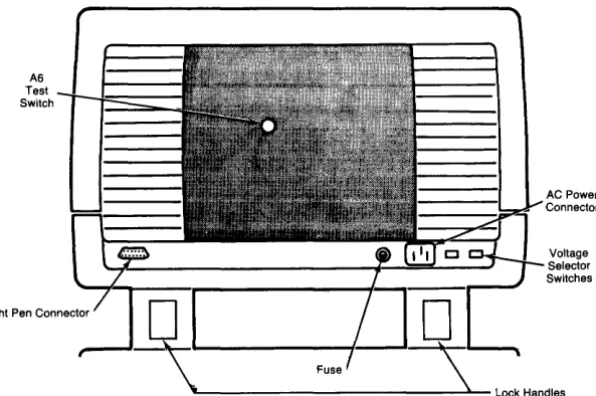
[image:10.380.28.326.108.306.2]A6 Test Switch
Figure 2-1. 98770A Back Panel
AC Power Connector
Chapter
3
Configuration
Base Configuration
The following assemblies must be installed in the 9845C base to support the 98770A. (These parts are included in the 98771A Upgrade Kit.)
98770-65501 Color graphics ROM 1818-1208 Mainframe ROM 1818-1209 Mainframe ROM
98780-65501 Enhanced graphics ROM 1818-1591 Mainframe ROM
or for either
98770-66534 Alpha control assembly (replaces 09845-66503 in Mainframe)
1818-1592 Mainframe ROM
See the 98458 CE Handbook Chapter for locations of these parts.
Interfacing
The 98770A interfaces to the 9845C base via the Alpha Control Assembly (98770-66534) and the Graphics Interface Assembly (09845-66504). Alpha information is stored in block 0 read-write memory, and is refreshed to the display via the IDA bus. Graphics information is transfer-red via the I/O bus to the display, where it is interpreted and entetransfer-red into the display memory.
Status Word
The Status Word may be obtained by executing the following instructions: (requires I/O ROM installed in mainframe)
STATUS 13;A DISPA
15 14 13 12 11
1 0 1 0 1 0 0 1
10 9
o
08 7 6 5 4 3
o
I
011I
0 0o
01 = Interrupts enabled
o
= Interrupts disabled0= ID Bits
1 =ID Bits
2 1 0
o
I
Oil
I
I
0[,
~
Soft Key
Interrupt
1 = Light Pen
Interrupt
Check
[s the base operating? (Try PR[NTER [S 0
PR[NT "HELLO")
[s there any display?
Adjust intensity control. Press control-stop [s there a cursor?
Check voltage select switches, fuse, and line power.
Still no display?
Chapter
4
Troubleshooting
Initial Checks
Action
Yes - Proceed with [nitial Checks. No - Fix base.
Yes - Proceed to Raster Checks No - Proceed with [nitial Checks.
Yes - Proceed to Raster Checks. No - Proceed with [nitial Checks.
Correct any fault.
Proceed to Inoperative Unit Checks.
Inoperative Unit Problem Chart
(Remove top cover.)
Symptom
Fuse keeps blowing.
Neither back panel fan runs.
Fan above voltage selector switches doesn't run.
Probable Cause
Fault in: Power Supply Rear Panel Assembly Transformer Spark Gap
Fault in: Rear Panel Assy Turn-On Relay Transformer
Fuse located below power supply (early units only).
Fault in: Power Supply or other area of unit. (See Power Supply Indicators) Fan
Proceed to Inoperative Unit Problem Chart -Power Supply Indicators.
4-2 98770 Troubleshooting
Inoperative Unit Problem Chart
Power Supply Indicators
Located on top left side of 98770 as you face front of display. See Page 9-8 this handbook.
Left 1 2 3 4 S 6 7 8 RIGHT 2 3 4
Left Group Right Group
o
3 4
Normally all off
Indication
8 4
Normally 1, 2, 3 off, 4 on
Cause
- 80V overcurrent. High Voltage, A44, AS, A6
- 80V overvoltage. A44, AS, A6, High Voltage
+ / -
lSV or+ / -
2SV overvoltage. AS,A44,A3,A2,A6+
12V overvoltage. A44,ASAS Heat Sink over-temperature. AS, defective fan, blocked air inlet.
Switching transformer primary overcurrent. - S.2V overvoltage.
AS, A6, A32, A13 (A33,AS3,AS4), Light Pen A2
+
SV overvoltage.A32, A11, A13 (A33, AS3, AS4), A6, A2
Linear 2 Switching Regulator inhibited. AS, Power Supply
Linear 1 Switching Regulator inhibited. Power Supply
Logic Switching Regulator inhibited. Normally on to indicate
+
i - lSV INT is pre-sent.Inoperative Unit
(Remove top cover)
I
CAUTIONI
BEFORE REMOVING OR INSTALLING ANY tl,SSEMBL Y DIS-CONNECT UNIT FROM POWER SOURCE BY REMOVING POW-ER CORD FROM BACK OF UNIT.
Note
As viewed from rear of unit the left-hand fan is ac powered, the right-hand fan is de powered.
Turn Unit ON
If no display, then observe Power Supply Indicators. See page 4-2.
Observe the fans. If the ac fan (left-hand) is not turning, check: a. Fuse
b. Power source (wall connector, power cord, etc.) c. Computer (use the turn-on fixture)
d. Primary wiring
Note
If the ac fan starts turning as soon as the power cord is connected. the power-on relay controlling it may be stuck closed.
If the ac fan is turning but the dc fan (right-hand) is not, check:
1. Number 4 LED in the right indicator group. If lit (brite), power supply is functional. Skip to Step 2.
2. If off (dark), Power supply is not powered or inoperative. Replace power supply and AS assembly and do this section again. (see AS and power supply procedure See Page 4-S. )
Check Which LED's Are
Lit
The following list is for Left indicator group of LED's unless otherwise stated.
LED #1 Lit
- SO Volt supply overcurrent.
1. Unplug power cord.
2. Disconnect high voltage assembly.
3. Plug in and turn on (no display will be visible).
a. All LED's dark, unplug power cord and replace H.V. assembly.
b. LED #1 still ON, unplug and remove A6 board.
4. Plug in and turn on.
a. All LED's dark, unplug power cord and replace A6 board.
b. If LED #1 still lit. go to minimum configuration tests See Page 4-S.
LED #2 Lit
- SO Volt supply overvoltage.
1. Unplug power cord
2. Replace AS and Power supply.
(See AS and Power Supply procedure See Page 4-S.)
4-4 98770 Troubleshooting
LED #3 Lit
± IS or ± 2S Volt Supply overvoltage.
1. Unplug power cord.
2. Do AS and Power Supply procedure See Page 4-8.
3. Plug in and turn ON. If LED #3 still lit. go to minimum configuration tests.
LED #4 Lit
+ 12 Volt Supply overvoltage.
1. Unplug power cord.
2. Do AS and power supply procedure See Page 4-8.
3. Plug in and turn ON. If LED #4 still lit, go to minimum configuration tests.
LED #5 Lit
AS heatsink temperature higher than 100° C.
1. Check air flow of internal fan (near bottom of heatsink) by holding hand above AS heat sink.
2. No air flow. Unplug power cord.
3. Remove AS and try to rotate fan by hand.
a. If frozen (will not rotate), replace fan.
b. If it spins, disconnect the fan and check the voltage at the connector (2S Vdc). Check the wiring to fan. See Page 9-3, 9-4, 9-S.
4. Do AS and power supply procedure See Page 4-8.
S. Plug in and turn ON. If LED #S still lit, go to minimum configuration tests.
LED #6 Lit
Switching transformer primary overcurrent.
1. Unplug power cord.
2. Replace power supply.
LED #7 Lit
- S.2 supply overvoltage.
1. Do AS and power supply procedure. See Page 4-8. 2. Go to minimum configuration tests, Page 4-S.
LED #8 Lit
+ S Volt supply overvoltage.
1. Replace AS board. See Page 4-8.
2. Go to minimum configuration tests. See Page 4-S.
Right Indicator Group
LED #1 or #2 or #3 lit.
1. Replace Power Supply.
Minimum Configuration Tests
Use this procedure when the unit has an inoperative power supply or will not indicate the presence of ± 15 Volts dc, or when primary wiring defects are suspected.
Minimum Configuration
Minimum configuration consists of:
1. Base assembly and mother board. 2. Power supply and primary wiring. 3. A5 board (98770-66505). 4. A44 board (98770-66544).
5. Turn on fixture or installed on Computer.
I
CAUTIONDO NOT RUN UNIT IN MINIMUM CONFIGURATION FOR MORE THAN 30 SECONDS AT A TIME. (MINIMUM PLUS A33 BOARD CAN BE RUN INDEFINITELY)
To achieve minimum configuration, remove:
1. The A6 board (98770-66506).
2. The All board (98770-66511). 3. The A32 board (98770-66532). 4. The A33 board (98770-66533/13/53/54). 5. The 98775-66501166504 board if present.
6. Three 503 boards (98770-66503). Note the order of removal to avoid reconvergence. 7. The 502 board (98770-66502).
8. Remove the CRT assembly (be careful to disconnect YOKE wiring under the CRT).
Preliminary Procedure
Plug unit into power source and listen to "wake-up" sounds as you turn unit on (ignore LEOS when base is turned OFF):
a. Relay closure click in top. b. All fans turning.
c. Steady beep from base is normal. There is no handshake.
d. Watch LED's. If any LED lit, do A5 and Power Supply Procedure. #4 LED in right indicator group normally lit (brite).
e. Retest. If LED still lit. replace A44 or Mother board (Rare).
f. Unplug unit.
Unit must pass the minimum configuration tests before proceeding to next page.
4-6 98770 Troubleshooting
Unit Rebuild
Do minimum configuration tests before proceeding with unit rebuild.
I
CAUTIONI
BEFORE REMOVING OR INSTALLING ANY ASSEMBLY DIS-CONNECT UNIT FROM POWER SOURCE BY REMOVING POW-ER CORD FROM BACK OF UNIT.
1. Install the A33 Board and test run.
a. Pass - Power supply comes up. #4 LED lit. all other LED's dark. no beep from mainframe.
b. Fail -If any LED lit, except #4, replace A33 board.
c. Test run (repeat Step 1).
2. Install the CRT and Yoke assembly. Make all connections to Yoke. but do not connect high voltage.
a. Pass - Power supply comes up, #4 LED lit, all other LED's dark.
b. Fail-If any LED lit, except #4, replace CRT and Yoke assembly.
c. Test run (repeat Step 2).
3. Connect high voltage.
a. Pass - Power supply comes up. #4 LED lit. other LED's dark. listen for HV crackle.
b. Fail -If any LED lit. except #4. replace high voltage assembly.
c. Test run (repeat Step 3).
4. Install the A6 assembly. Install all mounting screws.
a. Pass - Power supply up. display visible but no horizontal sync. (Retrace lines visible, convergence close but colors separated. no alpha, no graphics). #4 LED lit, other LED's dark.
b. Fail - Replace A6 assembly
c. Test run (repeat Step 4).
5. Connect Video cable from A33 to A6. Assure that the cable keys mate correctly.
a. Pass - Power supply up. Alpha display. convergence close but colors separated. no retrace lines. (If retrace visible. recheck cable for proper key.)
b. Fail - Double check cable key. Replace A33 board.
c. Test run (repeat Step 5).
6. Install the three 503 boards. one at a time (remember the order they were removed in)
a. Pass - Turn on after installing each board. Pov,;er suppl>-' up. Alpha. convergence close but colors separated. no retrace.
b. Fail - Replace the 503 board just installed.
7. Install the 502 board. Do not connect the cable.
a. Pass - Power supply up. Alpha present. convergence close but colors separated. no
b. Fail - Replace the 502 board. c. Test run (repeat Step 7).
8. Connect the cable on the 502 board.
a. Pass - Power supply up. Normal display. convergence close to normal. b. Fail - Double check the cable. Replace the 502 board.
c. Test run (repeat Step 8).
9. Install the 511 board.
a. Pass - Power supply up. No change in display. b. Fail - Replace the 511 board.
c. Test run (repeat Step 9).
10. Install the A32 board.
a. Pass - Power supply up. No change in display. b. Fail - Replace the A32 board.
c. Test run (repeat Step 10).
11. Install the 98775-66501 board (if present).
a. Pass - Power supply up. No change in display. b. Fail - Replace the 98775-66501 board. c. Test run (repeat Step 11).
12. Connect the video cable. Assure that the cable keys mate (if 98775-66501 present).
a. Pass - Power supply up. No change in display. b. Fail - Replace the cable or the 98775-66501 board. c. Test run (repeat Step 12).
13. Do complete diagnostics and alignment.
4-8 98770 Troubleshooting
A5 and Power Supply Replacement Procedure
I
CAUTIONI
BEFORE REMOVING OR INSTALLING ANY ASSEMBLY DIS-CONNECT UNIT FROM POWER SOURCE BY REMOVING POW-ER CORD FROM BACK OF UNIT.
Turn OFF and unplug unit.
Replace both AS and power supply with known good, new assemblies. If unit does not function properly, AS or power supply is not the problem. Turn OFF. unplug and reinstall original AS and power supply. Check out the primary wiring and the mother board assembly. Return to Inoperative Unit procedure or Minimum Configuration procedure.
If unit does function. do the following steps:
1. Remove new supply and reinstall original supply leaving new AS installed. Plug in and turn ON.
a. If unit operates, AS is the problem. Leave new AS in unit.
b. If unit still does not operate, supply is the problem. Reinstall the new supply. Leave new AS in unit.
Raster Problem Chart
Symptom
No display
Improper focus control.
No high voltage. No raster deflection.
Odd raster shapes.
Other raster-related problems.
Improper intensity settings. Color always on or off.
Loss of one color.
Improper purity. Improper blue lateral.
Improper convergence.
Cannot converge one color.
Retrace lines on before desired intensity reached.
Retrace lines "On" at power-up.
Cause
High voltage. A44. CRT
High Voltage. A44. AS. Power Supply
Yoke Assembly A44. AS. A44.AS
A44.AS
Cable not connected. A6. A13 (A33. AS3. AS4).9877S-66S01/66S04.
A6. A13 (A33. AS3. AS4). CRT
A2 A2.AS
A3.A2.AS
A3.AS
A6
Cable to A6 disconnected. A6, A13 (A33, AS3, AS4), 9877S-66S01/66S04.
Graphics Problem Chart
SymptomIncorrect lines being drawn.
Extra or missing lines.
Improper or no area fill.
Improper line type or no line type control.
Random or repetitive dots missing or always on display.
Intermittent display dots.
Groups of dots missing or always displayed.
Cannot read or write into graphics memory.
Softkey problem (no decoding)
Cause All All All All A32 A32 A32 A32
All, cable, softkey switches.
4·10 98770 Troubleshooting
Alpha Problem Chart
Symptom
No alpha display.
No graphics display.
Improper or incorrect characters.
Characters missing (character in lines) or incor-rect.
Incorrect colors or highlighting.
One or more cursors missing or incorrect.
No alpha blanking.
No graphics blanking
Cause
A13. (A33. A53. A54). A34
A13, (A33, A53. A54). All. A32.
98775-6650 I ;66504
A13. (A33. A53. A54). A34
A13. (A33. A53. A54), A34
A13. (A33. A53, A54), A34
A13. (A33. A53. A54)
A13. (A33. A53. A54)
Test Binary Diagnostics
Chapter
5
Diagnostics
1. Use the 9845B/C Test Binary Cartridge 09845-91031 (Rev. C or newer.) 2. Install the cartridge in TI5.
3. Key in: LOAD BIN "TBIN" ( EXECUTE). 4. Menu displayed.
5. Press
OU
orc:JiJ.
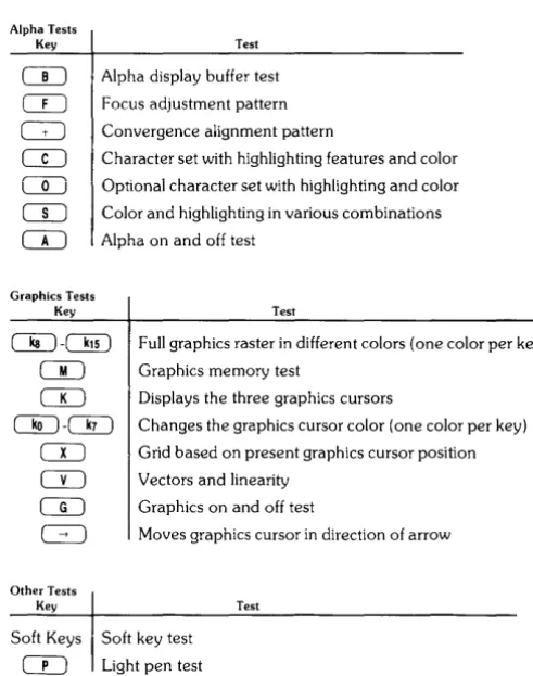
6. Table 5-1 is a listing of the tests contained on the disc. The procedures for individual tests start on the next page. (page 5-3).
Alpha Tests Key
Table 5.1 Test Binary Display Tests
Test
Alpha display buffer test
Focus adjustment pattern
Convergence alignment pattern
Character set with highlighting features and color
Optional character set with highlighting and color
Color and highlighting in various combinations
Alpha on and off test
Graphics Tests Key
ITJ-eJiD
CTI
CD
OU-OU
CIJ
CD
CD
G:J
Other Tests Key TestFull graphics raster in different colors (one color per key) Graphics memory test
Displays the three graphics cursors
Changes the graphics cursor color (one color per key)
Grid based on present graphics cursor position Vectors and linearity
Graphics on and off test
Moves graphics cursor in direction of arrow
Test
Soft Keys Soft key test
CO
Light pen test [image:23.381.79.325.225.537.2]5-2 98770 Diagnostics
Alpha Tests
CTI
Alpha Display Buffer TestPress
CTI;
the CRT displays:This test checks the 80-character line buffers on the A34 assembly, plus the ability to display information.
co
Focus Alignment PatternPress
CO:
two columns of the word "FOCUS" appear. Check the characters to ensure they are clear and readable. If necessary, remove the display's top cover and adjust the focus control to achieve the best overall character focus (refer to Chapter 6 for adjustment procedures). Itmay not be possible to achieve perfect focus in all areas of the display.
c:±:J
Convergence Alignment Patternco
Character Set With Highlighting Features and ColorPress
CO ;
the CRT displays:Note
To see black, press one of the graphics color keys,
GJ
throughO!D.
This test checks the character ROM and the highlight and color latch on the A13, A33, A53, or A54 assembly.
CD
Optional Character SetsPress
CD;
if an optional character ROM is installed (Option 771 or 772), the optional characters are displayed.If test fails replace the A13 (A33, A53, A54) assembly
Note
5-4 98770 Diagnostics
co
Color and Highlighting in Various CombinationsPress
CO ;
the CRT displays:Note
To see black, press one of the graphics color keys,
CJ!J through
DiD.
If test fails replace the A13 (A33, AS3, AS4) assembly
CD
Alpha On and Off TestPress
CD ;
the alpha display should disappear. PressCD
again, the alpha display should appear again. PressCD
again to enable next test.Graphics Tests
c:§:J .
C!!D .
Full Graphics Raster in Different ColorsPress any key from
c:§:J
throughC!!D :
a colored graphics raster will appear. Refer to Chapter 6. page 6-5. for color intensity adjustments.Here is a summary of the keys and the color each key produces.
Key
i
Colorc:§:J
WhiteOU
Red~ Yellow
CJiiJ
GreenDiD
CyanC§J
BlueDiU
MagentaC!!D
BlackThe test checks the graphics memory and color assignment logic on the A32 assembly.
CI)
Graphics Memory TestPress
CI) ;
the three graphics memories on the A32 assembly are tested.Memory errors are dispiayed on the following format
Example X Dot Location
Y Dot Location
Memory Number
Actual Data Expected Data
GRAPHICS X:OOOOO ; Y:OOOOO ; MEM#:OOOOO HAS 000000 NOT 000000
The 98770A Service Manual shows how to isolate this error message to a single memory chip.
CTI
Graphics CursorsPress
CTI ;
initially the small horizontal line cursor (-) appears. PressCTI
again and the full screen cross-hair cursor appears. PressCTI
once more to view the small cross-hair cursor.This test checks the graphics cursor logic on the A13, A33, A53, or A54 assembly.
~
- OQ
Graphics Cursor ColorPress any key from ~ through
OQ
to change the color of the graphics cursor. Here is a summary of the keys and the color cursor each key produces:Key Color
~ White
OU
RedOQ
YellowOLJ
GreenOU
BlueCJQ
MagentaOQ
BlackCD
GridPress
CD ;
a grid is produced, based on the present position of the graphics cursor.5-6 98770 Diagnostics
CL)
Vectors and linearityThere are several sections to this test. Press ( CONTINUE) anytime to return to main Menu.
Press
CL) ;
the first display is five horizontal lines to be used for vertical linearity.Using the alignment mask, ensure that the center line is aligned to the center line of the alignment mask. Then align the bottom and top lines with those on the mask. Refer to Chapter 6 for vertical linearity adjustment procedures.
Press
CL):
the next pattern is vertical lines for horizontal linearity.Press
CL) ;
the following display appears:Press
o=J ;
the display shows the 16 area fill patterns and the 8 line types.5-8 98770 Diagnostics
Press
CD
Press
CD
CTI
Graphics On and Off TestPress
CTI ;
the graphics display should disappear. PressCTI
again, the graphics display should appear again. This test checks the graphics blinking circuit on the A13 (A33, A53, A54) ~~~~_\...1 ••a~,:,t:lllUly.
Ensure that graphics is on and press the arrow keys to move the graphics cursor.
( .... )( .... )( i )( ~ ) Move Graphics Cursor
The arrow keys allow graphics cursor movement within the graphics raster.
Other Tests
Soft Key Test
Press each of the keys on the lower front bezel of the display. An X appears above the key that was pressed. Must be in Main Menu; not Graphics.
CLJ
Light Pen TestPress
CLJ;
a self test is performed on the light pen's position circuits.Press (CONTINUE); position the pen over the cursor and press the "pick" button. "ok" should appear on the display. This tests the ability of the light pen to pick a point.
Press ( CONTINUE); point the light pen at the cursor. Check the offset and field values. The offset value should be 8 ± 3.
The field value should be greater than 18.
Press (CONTINUE); point the light pen at the cursor. A threshold shift test is performed. OK
5-10 98770 Diagnostics
98458 Test Tape Diagnostics
Tools Required
#2 Pozidriv Screwdriver Alignment Tools (non-metallic)
(Recommend HP part no. 8710-0033 and 871O-0933)
Adjustment Summary
Chapter
6
Adjustments
Complete alignment of the 98770A is accomplished in the following order:
Adjustment
Preliminary High Voltage Focus Purity Color Intensity Convergence (Prelim) Raster Position Raster Size Raster Shape Vertical Linearity Convergence (Final) Page 0-.3 6-3 6-4 6-4 6-5 6-6 6-7 6-7 6-8 6-10 6-6
Where to Start Adjusting
Assembly ReplacedCRTlYoke High Voltage Unit 98770-66502 98770-66503 98770-66506 98770-66544
Start at (and do all subsequent)
Preliminary Adjustments High Voltage
Purity
Convergence (Final) Color Intensity High Voltage
6·2 98770 Adjustments
A6 Adjustments
Back
Fan
Focus Adjustment
Top and Bottom Pincushion
Vertical Centering
Top and Bottom Ratio
Convergence Adjustments
A44 Adjustments
Right Side
Front
Preliminary Adjustment
Use this adjustment procedure when adjusting a badly misaligned unit, or one in which the CRT /Y oke assembly has been replaced.
Procedure
1. Set the switch on the A13 (A33. A53. A54) assembly to its forward (red raster) position.
2. Turn the high voltage control (A44) fully CCW for the maximum high voltage
3. Adjust the brightness controi (under iower ieft edge of dispiay unit) ciockwise for a visibie raster. If none appears, adjust the RED color intensity control (A6) until a raster appears.
4. Depress the A6 test switch and adjust the focus control for the sharpest retrace lines.
5. Adjust the two A2 purity controls for an even red color throughout the raster.
6. Adjust the A44 height. width. vertical. and horizontal centering so all raster edges are at least 1 cm inside the screen edges. Touch-up the A2 purity controls if necessary for optimum red purity.
7. Perform a preliminary color intensity adjustment per the procedure on page 6-5.
High Voltage
"t"";lW~iji
DO NOT ATTEMPT TO MEASURE THE CRT ANODE VOLTAGE.
This adjustment sets the high voltage level for the CRT anode.
Procedure
Note
If the A6 video drive assembly has been changed, perform a pre-liminary color intensity adjustment before proceeding.
1. Set the switch on the A13 (A33, A53, or A54) assembly to its rear (white raster) position.
2. Set the brightness control to maximum.
3. Turn the High Voltage adjustment (A44) fully CCW for maximum high voltage.
6-4 98770 Adjustments
Focus
Use this adjustment (High Voltage Unit) to set the CRT focus grid voltage to a value which gives the best overall character focus.
Procedure
".j.';lwnCi
USE A NON-CONDUCTIVE ALIGNMENT TOOL WHEN ADJUST-ING THE FOCUS CONTROL.
1. Set the A13 (A33. A53. A54) assembly to its center position.
2. Use the 9845B/C binary test cartridge (Rev. C or newer) to display the focus pattern. (Refer to Chapter 5.)
3. Turn the focus control to achieve the best overall display focus of the displayed charac-ters.
Purity
This adjustment varies the current in the purity coils so that the beam from the red electron gun strikes only the red phosphor.
This adjustment is interactive with the Raster Position adjustment, and affects Convergence.
Procedure
1. Execute "DEGAUSS" from the keyboard. (Exit Test Binary first by pressing
DiD ).
2. Set the A13, A33, A53 or A54 switch forward for a red raster.3. Adjust the brightness control and the color intensity control (A6) as necessary to produce a medium-bright red intensity level.
4. Adjust the A44 width, height, and centering controls until all raster edges are visible. 5. Turn the vertical and horizontal purity controls (A2) to obtain a pure red raster. 6. Readjust the raster position.
Note
Color Intensity
This adjustment sets the screen grid bias for the red, blue, and green electron guns to proper levels.
In a complete alignment. this adjustment must be done twice because it both affects and is effected by other adjustments. A rough color intensity adjustment should be done prior to high voltage adjustment, and a fine adjustment should be done prior to convergence.
Set the switch on the A13 (A33, AS3, AS4) assembly to the rear position to display a white raster. Turn the brightness control to the minimum brightness position (full CCW).
Procedure
Perform this procedure in normal room lighting.
BEWARE OF THE FANS WHEN MAKING ADJUSTMENTS WITH THE REAR PLASTIC COVER REMOVED.
1. Adjust the 3 color intensity controls (CCW) (A6) until none of the three rasters are visible. (Use an insulated tool only.) If necessary, remove the metal shield.
'''''iuma
REMOVING THE METAL SHIELD EXPOSES LETHAL VOLT-AGES PRESENT ON THE A6 ASSEMBLY.
2. Adjust the green color intensity control clockwise to produce a dim but entirely visible green raster. Turn this control 113 turn more CW from this setting.
3. Adjust the red and blue color intensity controls to cause the raster to appear gray and very slightly increased in brightness from step #2.
4. Turn the brightness control slowly toward maximum brightness, looking for any domi-nant color or tint appearing as the raster changes from gray to white.
5. Adjust the appropriate color intensity control to minimize any objectional color tinting over the brightness range from gray to white. Disregard tinting in small areas which may be related to misconvergence or less-than-perfect purity.
6-6 98770 Adjustments
Convergence
This adjustment converges the red, green and blue electron beams so that as the beams scan across the display area, all beams scan in unison as one dot.
Set the switch on the A13 (A33, A53, or A54) assembly to its center position (Normal position).
Adjust brightness full CW (maximum brightness).
Procedure
1. From the keyboard, type in CONVERGE and press execute.
2. A"
+"
character will appear on the screen along with a number on the right-hand side . • The"+"
character is used to converge the three beams in the area that the"+"
appears .
• The number on the right-hand side indicates the step number (13 total) and it appears directly opposite the convergence controls used for that step.
3. On all 13 convergence steps,
a. converge the red and green"
+"
to make yellow. b. converge the blue"+ "
to make white.c. If on Convergence steps 1, 6, or 8, refer to procedural step 4 below. d. press ( CONTINUE)
4. On steps 1, 6, and 8, you may have to adjust the blue lateral adjustments. (A2)
If the blue is to either side of the converged
+,
use the appropriate blue lateral adjust-ment to center the blue+
horizontally on the converged red and green+.
Example
On step 1 adjust the center blue lateral On step 6 adjust the left blue lateral On step 8 adjust the right blue lateral
Red moves along an upper right to lower left line / ' Green moves along an upper left to lower right line' Blue moves vertically up and down
t
r,)iiiiiiiiiiiiiiiiiiiiiiiiiiiiiiiiiii All 13 Steps iiiiiiiiiiiiiiiiiiiiiiiiiiiiiiiii" Steps 1. 6 and 8
A Converge Red and Green
to Make Yellow
B
Converge Blue to Make White
Raster Position
Two adjustments, horizontal and vertical centering (A44), are used to position the raster in the center of the CRT screen.
The raster position adjustments are interactive with and affected by:
• Raster Size adjustments
• Raster Shape adjustments
• Purity adjustment
These adjustments should be performed after the initial raster position adjustment; then, recheck the raster position and readjust as necessary.
Set the switch on the A13 (A33, A53, or A54) assembly to the rear to display a full white alpha raster.
Procedure
1. Center the raster horizontally with the horizontal center control. 2. Center the raster vertically with the vertical center control.
3. Touch up convergence as necessary (see CONVERGENCE, page 6-6).
4. Check and perform, if necessary, the raster size, raster shape and purity adjustments.
Raster Size
Two adjustments, raster width and raster height are used to dimension the raster to the proper size.
You may have to readjust the raster position slightly after sizing.
Set the switch on the A13 (A33, A53, A54) assembly to the rear to display a full white alpha raster.
Procedure
1. Adjust the raster width and height so that the displayed raster is the same size as shown in drawing.
2. Adjust the raster shape and readjust the raster position as necessary.
19. ,cm
L127xm
25.5cm
\. ---.-/
6-8 98770 Adjustments
Raster Shape
Once the raster is positioned and sized, the raster shape adjustments are used to straighten and proportion the raster sides to obtain a rectangular raster.
The raster shape adjustments interact with each other and may affect the raster size.
Set the switch on the A13, (A43, or A53) assembly to the rear to display a full white alpha raster.
Procedure
1. Adjust the phase control to make the edges of the raster equal in height.
[
J
WrongT
1
Correct • 0 0 Left and Right Sides Equal
1
1
Note
If the raster appears tilted after this adjustment (with the bezel seated evenly), remove the bezel assembly, loosen the four screws securing the CRT assembly and tilt the CRT assembly as necessary to correct the raster tilt. Tighten the four screws securing the CRT assembly, reseat the bezel assembly evenly and recheck the raster tilt.
2. Adjust the top and bottom ratio control to produce an equal but opposite shape on the top and bottom edges of the raster.
3. Adjust the side pincushion control (A44) to straighten the left and right edges of the raster.
Incorrect Left and
Right Edge PincuSrlion
Wrong
Straight Left
and Right Edges
Correct
4. Adjust the top and bottom pincushion control (A44) to straighten the top and bottom edges of the raster.
Incorrect Top and Bottom Ed,\ Pincushion
Wrong
Straight Top and Bottom Edges
Correct
6-10 98770 Adjustments
Vertical Linearity
These adjustments affect the vertical raster size. Recheck the raster size after making these adjustments.
Refer to drawing 1 below and mark the center of the CRT screen with a wax marker or pencil. Do not use a felt or magic marker. Drawings 2 and 3 show the relative spacing for the vertical and horizontal patterns.
For the 9845B/C computer use the Binary Test Cartridge (Rev. C or newer): or for the 9000
computers use the 9000 Integrity Test Disc. to display the test patterns.
1. Remove the top cover of the display. Set the switch on A13. A33. A53. or A54 to its center (normal) position.
2. Adjust the vertical center control to align the center line of the display with the center of the CRT found above.
3. Refer to drawing 2 and adjust the vertical height and null controls as necessary to position the outside lines of the display. Assure that the center line remains at the center of the CRT.
4. Adjust the vertical linearity control to obtain near equal spacing between the horizontal line in the areas between the Top. Center. and Bottom lines.
5. Display the focus pattern. Readjust the null and linearity controls as necessary to obtain equal character height throughout the pattern.
6. Display the horizontal centering pattern. Adjust the horizontal centering and the horizon-tal size to obtain the pattern in drawing 3.
1
9.75cm
+
1
r
I
11l
8~m
I
---+----4-1
+
_ _
-L-tl
2
Vertical Centering
,- 9.75Cm~
...
1-...
- - - 1 9 . 5 c m - - - . j - 13
Horizontal Centering
Final Convergence
As the previous adjustments may have affected convergence, a final convergence adjustment should be made at this time (see CONVERGENCE, page 6-6).
Chapter
7
Peripherals
Chapter
8
Replaceable Parts
Repair Philosophy
Most 98770A repairs are done by replacing the faulty assembly. The old assembly is returned for repair in some cases (exchange program) and is thrown away in others. In a few cases, a faulty assembly can be repaired to the component level either on-site or at the local field office. This procedure is recommended only when replaceable components are not soldered in or when the probability of inducing further damage in the course of doing the repair is minimal. All components which may be replaced by the CE are listed as level 2 parts under the assembly part number in the parts list. Other failures should be repaired at the assembly level. All exchange parts are noted as such in the parts lists.
8-2 98770 Replacement Parts
98770 Part Numbers
Assembly Reference
CD HP TQ Description
Level Designator Part No.
0490-1235 Power Switch Relay 1970-0050 Spark Gap
2110-0051 Fuse - 10 Amp Normal Blow (for 110VI 2110-0056 Fuse - 6 Amp Normal Blow (for 220VI 2110-0543 Fuse Holder
2110-0545 Fuse Holder Cap 3101-2298 Voltage Selector Switch 9135-0123 line Filter 98770-61601 light Pen Cable Assembly 98770-61602 Upper Transistor Socket and Cable 98770-61603 Lower Transistor Socket and Cable 98770-61604 Soft Key Cable (from motherboardl 98770-61605 Intensity Control Assembly
2100-3833 Variable Resistor 250K 5040-8149 Thumb Wheel 98770-61606 High Voltage Power Cable 98770-61607 A6 Assembly Power Cable 98700-61608 Start-Up Transformer 98770-61612 Power Supply Connector Assembly
AO 98770-66500 Motherboard
R1 0698-3441 Resistor - 215 ohm, 1 'Yo, 1/8 watt J13 1251-0599 Connector - 3 pin male Jl8.27 1251-1365 Connector - PC 44 contact J17,25,28.31 1251-2026 Connector - PC 36 contact Jl-4,23 1251-2035 Connector - PC 30 contact J15, 16, 19,24, 1251-2915 Connector - PC 50 contact
J26,29
J7,8 1251-2916 Connector - PC 36 contact J14 1251-3198 Connector - 15 pin male J9,1l 1251-3403 Connector - PC 20 contact
J22 1251-3475 Connector - 10 pin male J20,21 1251-3767 Connector - 7 pin male
J5 1251-4672 Connector - 10 pin header J12 1251-4882 Connector - 7 pin post-type JlO 1251-5153 Connector - single contact
J6 1251-7623 Connector - 10 pin male Al 98770-66501 Motherboard - old version A2 98770-66502 Convergence Waveform Assembly
A3 98770-66503 Convergence Output Assembly
A4 98770-66504 Deflection!HV Assy-old version-See 98770-66544 A5 98770-66505 Transistor/Heat Sink Assy-Exchange part 98770-69505 Q15,16,19.23 1853-0059 Transistor -2"'3791
Q29,33
Q1 1853-0305 TranSistor 2N5875
Q9 1853-0351 Transistor -2N6053 Q4 1854-0063 Transistor - 2N3055
QlO,26,28 1854-0264 Transistor 2N3715 Q2L34 1854-0848 Transistor 2N6584
Ab ':Jbl'V-bbJUb video Amp Assy-Excnange pan ':;;I(:)IIV-O'::1:Juo
All 98770-66511 Vector Generator Assy-Exchange part 98770-69511 A13 98770-66513 Display Logic Assy-old version-See 98770-66533 A32 98770-66532 Graphics Memory Assy-Exchange part 98770-69532 UI-48 1818-0391 48 lC-16KRAM
1'\" 9R770-/i/iS" Di,ry'ac' Logc .l\ssC'-E,change ryart 9R770-/i9S33 A44 98770-66544 Deflection, HV assy-Exchange part 98770-69544 A53 98770-66553 Display Logic Assy-Katakana old version-see 98770-66554 A54 98770-66554 Display Logic Assy-Katakana-Exchange part 98770-69554
98770-67901 High Voltage Assy 9100-0485 High Voltage Transformer
Assembly Reference CD HP TQ Description
Level Designator Part No.
1 1 98770-68502 2 DC Fan Assembly
1 6 98770-69505 1 Transi~orlHS Assy-Exc:han~
1
I
7I
98770-69506 1I
Video Amp Assy-Exchange 1 4 98770-69511 1 Vector Generator Assv-Exchanqe 1I
9 98770-69532 1
I
G,"~_,",~~-1 0 98770-69533 1 Display Logic Assy-Exchange1
I
5 98770-69554 1 Display Logic Assy-Exchange1 0 98770-69971 1 CHTN oke Assy-Exchange
1 1 98770-69980 1 Power Supply-Exchange
1 1 98775-66501 0 Ught Pen Control Assy-old version-See 98775-66504
1 4 98775-66504 1 Ught Pen Control Assy
1 1 98775-67971 1 Ught Pen Assy-Exchange part 98775-69971
1 5 98775-69971 1 Ught Pen Assy-Exchange
Motherboard Connectors
1251-2026 1251-1365 1251-2026
1251-3403
1251-2916
8-4 98770 Replacement Parts
A5 Transistors
-25V +25V
on Case on Case
Q4 01
- 25V Regulator + 25V Regulator
Pass Transistor Pass Transistor
1845-0063 1853-0305
2N3055 2N5875
010
'j
09Blue Lateral Output - 5.2V Regulator
1854-0264 Pass Transistor
2N3715 1853-0351
2N6053 016
Blue Lateral Output 015
1853-0059 Convergence Output
2N3791 1853-0059
2N3791 (RED)
021
..
~.
019 High Voltage Output
Convergence Output
1854-0848 I.,
1853-0059
2N6584 2N3791 (GREEN)
026 023
Horizontal Linearity Convergence Output
Output
,..,
1853-00591854-0264 2N3791 (BLUE)
2N3715
028
029 Vertical Output
Horizontal Linearity 1854-0264
Output
,
~~
2N3715 (+21V)1853-0059
2N3791 033
Vertical Output
034 1853-0059
Horizontal Output 2N3791 (- 21 V)
1854-0848 2N6584
Power Supply 98770-67980
High Voltage Assembly 98770-67901
Bezel Assembly 98770-69301
Chapter
9
Diagrams
Assemblies Under the Top Cover
A5 Removal Screws
A3 (3 each) Convergence Output
98770-66503
A 13, A33, A53, A54 Display Logic Assembly
A11 Vector Generator
98770-66511
A32 Graphics Memory
98770-66532
Light Pen Control 98775-66504
A2 Convergence Waveform
98770-66502
9-2 98770 Diagrams
Power Connector
Focus Lead Connector
Rear Panel Assemblies
Video Signal Connector
Ground Connector
Chassis Assemblies
CRT Connector
A6 Power Cable
DC Internal
Fan
High Voltage Drive Cable
DC Fan
Spark Gap
Line Filter
Power On Relay
One Amp Fuse for
± 15V Internal (Eariy units oniy)
Motherboard
Brightness Control
Cable to A2 Assembly
Start Up Transformer
SWITCH
S1
98
8
Rear of Machine
SWITCH
S2
See wiring d" lagrams that follow.
Primary W' . trIng
9-4 98770 Diagrams
BRN
110 VAC
6
BlU
RELAY
If
928_---u..
O)---,-,W-H--T---:/.::,~4=E~::::./---:G:::R---:A---OJl-4,5,
D,E
SPARK GAP
S2
o
S2
958
WHT/GRN/GRA Jl-7,8,
T
H,J
110 VAC
8
1
~---+---G::-'R=-A:---oJHO,ll,
l,M
918 WHT/BRN/GRA
98 WHT/GRA
958 WHT/GRNIGRA
98 WHT/GRA
RELAY
~
8GRA
948 2A
1A
WHT/YELIGRA o BlK
2 L-_+-~~---'
04
BlK/YEl
BRN
220 VAC
I
RELAY Of'f.-_9--02--'8c----{JJr _ _ _ _ _ ---:-:-:-=-:=9-=4"'8-::-:-_ _ _ _ --oJI - 4 ,5,
WHT/YEL/GRA D,E
S2
958
Or---:W:-cH-:-:T=-/:':G-=R.::':N--:-/G=-R=-A-:---OJI-7, 8,
T
I
I
I
SPARK
GAP
'----8~
....
r--~O~
220VACS2
1
1
H,J I
918 WHT/BRN/GRA
,---<~---C;::-,:=-A-:---<OJ1-10,II,
L,M
98 WHT/GRA
958 WHT/GRN/GRA
948 WHT/YEL/GRA
Switch in 220V Position
9-6 98770 Diagrams
CRT Handling
Deflection Yoke CableConnector R e a r
-Ground Cable Connection
Purity and Blue lateral Yoke Connector
CRT N oke Cables
Convergence Yoke Cable Connector
Light Pen Installation
Video Cable 8120-2988
Light Pen PC Assembly Installation
Original Video Cable A 13 to Rear Connector
8120-2988 Video Cable Connections
Light Pen Video Cable Forward Connector to A6
8120-3073
9-8 98770 Diagrams
Power Supply Checks
The power supply test points are shown in Figure 3-2. Table 3-2 lists the voltage tolerances for each supply.
Test Points on Top Cover
Power Supply Test Points
Right Indicator Group
Test Points on Side
Power
Supply
Assemblies
The power supply assembly (98770-67980) is an exchange item; however, here is a list of the power
supply PC assemblies and the circuits found on each assemblv.
98770-66507 (A7) Primary Assembly
Degauss
Energy Storage Circuit (less 2 big capacitors)
Switching transformers
Switching regulator filter inductors Surge limit relay
98770-66508 (A8) Filter Capacitor Assembly
Filter capacitors for the output voltages of the switching regulators. Voltages enter the 98770 motherboard via this assembly.
98770-66509 (A9) Control Assembly
Filament supply rectifiers and filter
Regulators for filament, ± 15 INT and + 12 supplies Pulse width modulators
Frequency response shaping
HSYNC synchronizer (phase-locked loop) Voltage/ current sense
LED indicator drivers
98770-66515 Switching Assembly
Current sense transformers
Switching transistors for the switching regulators
98770-66516 Rectifier Assembly
Rectifiers for the switching regulators
11~
'5Vln"m"+15VINTReclilierand Regula10r -1SVINT Sel·Up FllamenlVoUaqe 63Vdc
Tran5formf~r ;[~Fllamenl '~vOHage
TemperalureSensor Inpu! From AS RegulatofsOn
~:~5~_m~~ __ _____________ "'
1 .
Mnemonic Description Mnemonic Description
ABL Alpha Blanking LXA Load X Address AS Alpha Select LXC Load X Cursor Position
AVC Address Valid Clear LYA Load Y Address BADR B Address Lines LYC Load Y CUTsor Position
unv Diue Aipha VIdeo ivii VIdeo Video Uata hom Memory 1
BGV Blue Graphics Video M2 Video Video Data From Memory 2
BLKG Blinkino M3 Video Video Data From Memory 3 BR Bus Request MC
BV Blue Video MSO Memory Select Line 0
BVD Blue Video Data MSI Memory Select Line 1
C80 80T~ Character MSYNC Memory Synchronization
CAS Column /\ddr€5S Strobe NCS N COUU(t:!T St:!ied CEBG Chained External Bus Grant NL New Line
CL NP New Page
COLOR Color Select Lines NW New Word CRT CRT Status Line NWE New Word Enable CURS Cursor
OC Output Clock CSTM Internal Start Memory Cycle OL Output Latch
DO Memory Data Out Lines OS Output Strobe DOUT Data Out PA Peripheral Address Lines
DMAR Direct Memory Access Request PBR Peripheral Bus Request
DSP Display PEBG
Peripheral External Bus Grant
EBG External Bus Grant PSMC Peripheral Synchronous Memory Complete
tOL End of Line RAS Row Address Strobe
FB Full Brightness RAV Red Alpha Video FLB Full Lme Buffer RGV Red Graphics Video
FLG Flag RNP Reset New Page
GAV Green Alpha Video ROW Row Select
RV Red Video GGV Green Graphics Video RVD
Red Video Data GS Graphics Select
GV Green Video SCM Store Color Mask
GVD Green Video Data SGD Select Graphics Display
HIGH Highlight Select Lines SLT SMC Select Line Type Store Memory Control
HLT Halt STM Start Memory HSYNC Horizontal Svnchronization
STS Status
ICI Register Select line 1
TCK Buffered Mainframe Clock
IC2 Register Select line 2
IDA Instruction, Data. Address Bus Lines UL Underline
INlT Initialize VGC
Vector Generator Clock
INT Interrupt VBusy
Vector Generator Busv
10SB Input / Output Strobe V Ready
Vector Point Ready
IRH High Level Interrupt V SYNC
Vertical Synchronization
IRQ Interrupt Request
IS Input Strobe WE Write Enable Lines
LDA Load Address WW Write Word
LEP Load End Point XADR X Memory Address Lines
LlOD Latched 100 Bus Lines {Internal) YADR
Y Memory Address Lines
LTE Line Type Enable YSCAN
Y Timmg Chain Output Lines
9-12 98770 Diagrams
Replaceable Mechanical Parts
The replaceable mechanical parts of the HP 98770A Display are listed in the following table. The table is organized to list the parts that go together in groups. The major assembly is listed first and the hardware needed to attach it to adjoining assemblies is listed next. The "Ref. Desg." is keyed to the exploded view drawing that appears after the table. Not all parts listed appear on the drawing.
Selected Assemblies Part Numbers
Assembly Reference
CD HP TQ Description
Level Designator Part No.
98770·64405 Top Cover 3050-0066 Rat Washer
0515-0067 Screw. M3.5 X 0.6-lOmm. Pan head 98770-64404 Front Bezel
2a 3101-2400 Soft Key Assembly 3050-0066 Flat Washer 0535-0007 Nu\; M3.5 X 0 6. Hex 2b 98770-61206 Convergence Panel
2c NA Switch Bracket Assembly. Includes Next Two Parts
1600-1066 Bracket. Switch 0490-0744 Switch. Reed 0624-0314 Screw. Pan head. Plastlte 3050-0066 Flat Washer 0624-0347 Screw. Flathead. Plastite
2d S041-2386 Door
9164-0119 Magnet (on rear of door)
98770-64401 Base
3a 98780-67977 Locking assembly. Right Foot 3b 98780-67978 Locking Assembly. Left Foot
7120-8677 Set Error Cards
7101-0569 1 Cover. Error Cards 0624-0400 4 Screw
3c 98770-61605 Brightness Control Assembly 2190-0918 Lock Washer 0624-0403 ScreI.A.
3d NA Cover Hold Down Latch. Includes the next four parts 1460-1982 Pawl Spring
1480-0083 Pawl Pin 1600-1310 Bracket 1600-1327 Latch Pawl 2190-0918 Lock Washer 0624-0403 Screw
3e 98770-68502 DC Fan
3f 98770-01205 Mounting Brackets
2190-0918 4 Lock Washer
USlS-ULlb/
"
Screw. MJ 5 X U b-lUmm. Panhead3050-0066 Flat Washer
r
2190-0918 Lock Washer
0515-0068 Screw. M3 5 X 116-16mm. Pan head 98770-66S01 0-lother Board
43 98770-66511l !ntercon:lect Boa:-c
211)0-0918 14 Lock \Vasher
0624-041J:1 I~ Screv.!
4h Y~7711-lil211" I Heat ':-oinK Brackl:'t
0624-04o:l 2 Screw. Plastlte
4c 98770-66505 Heatsrnk Assembly
5d 5e 5f 63 6b oc 6d 6e 6f 6g 7a 98770~61201 0624~0402 0624~0403 2190~0918 98770~66503 98770~66502 1600~0907 2190-0918 05150067 98770~01202 2190~0918 0515-0066 30S0~0066 O3S0~0006 0403-0002 0515~0069 98770-01206 OSIS~0080 1600-0989 98770~60201 98770~61609 0360~1134 0490~1235 1251~2357 3101229S 9135~0123 98770~61608 9R770~61612 98770~68S01 2190~0004 0515~0055 98770-68502 30S0-0716 2190~0004 2190~0003 OS15-0055 98770~66506 98770~00601 2190~0918 0515~0069 5041~23SS 30S0~0071 2190~0017 0535~0006 98770-67970 3050~0071 2190~091S 0515~0066 9S770~04101 9S770~67901 404O~1733 2190-091S 0624~0034 98770~67980 2190-091S 0515~0066 0515-0067
....
12 2
Main Bracket Assembly Screw. PlasHte
I
Screw. PlastlteLock Washer
I
Convergence Board
Waveform Board
Convergence Bracket T ock VJasher D nh,..,,,,,-l
I
~crc\\" M3 5 X 0 6 lOmm .. 3"" ...I
Top Cover BracketLock Wasr erX 0 6-6mm. Panhead Screw. M3 S
Flat Washer Round Spacer
~~;::u::~r
XO.6~25mm.
Pan head P C Tie Down Bra~et . Flathead Screw. M3.5 X 0 6~ mm LP Tie Down Bracket Rear Panel Assembly bly. IncludesPnmary- Wmng Assem
The Next Seven Parts Barrier Block Relay. Power Switch AC Power Connector Slide Switch
~~~~i~~:nsformer
AssemblyEdge Connector A<sembly
Ar Fan.
'l~;ernal
LockW;~h~~
Panhead Screw. M3.0 X . ~ _DC Fan Flat Washer Internal Lock Washer Lock WMas;~'xSt~:~~gm Pan head
Screw,
Video Board Rear Shield
Lock Washer 6 25mm Pan head Screw. M3.5 X 0 ~ .
Rear Cover
Flat Washer Lock Washer
Nut. M4.0 X O. 7'b~e~ot a mechanical part. Light Pen Assem y.
Display Assembly Flat Washer
Lock W~s;~r X O.6~6mm. Panhead
*~::Mou~t
Bracket. Plate High Voltage Assembly BaffleLock Washer Screw. Self Tappmg Power Supply
5 9-13 98770 Diagram
Light Pen i3~t)~
.~~ ~~
Dome Switch UJ w 0 (])
/Switch
S~obe
:8
~
~~~~==~~4---J~
~,--l:---+i
__ ---,
'oltkge _\ Gain Comparator 'Tlplifier
Pen Controller
....
Y
Latch Y Window Latch Y HI
r.····.···
I?J
Left Hit X
Lo HitY Address (Y LO)
.'."
X
Window ~ u c
~
x
I
.'.", ,r BI)!,;
~~~y;:-,
~
Address (X Left)
~ .~§uft~red y Sca[\p,l~"~~~~~2~
~-+---4~~---~
" ~.
~-~~mh ~
Hit HonzontalLine
~
t~~1
',"'" ~
r_---~li<., ••. '~4----P.~~.j----~---~~----~
A
1j
and Window
X Counter Generator Vertical Line t - - - I iIH---f/;~~--+---+--+----H ...
I
~ and Window ff( Vert Retrace
I;::' Generator - f - - -:;.;J---~.::::..:...:...:.::::.:..:::.:::..:::.._+_+_+_-_+_ ...
I~~
l
~
~
____r_---~~---~v~;+_X~c~ou~n~te~r~L~oa~d~==;r~;~~~::~--~----~;~,".~~
~----~--~--~~~:~:---~F~~t__--~Dki~~
I - - H Blank
.---Video Mixer
' . . : ...
Fu!1 Bright !n
Red In Green In Blue In
Full Bright Out
From Display Logic A13 From Mainframe From Display Logic A13,A33, A53,A54
Red Out ".. To Green Out Video 1---B=I.:..:u:.:e:.:..:O.:..:u::.:t::.:---. . Amplifiers
A6
f;/ ~;; Sync
Control
L-_ _ _ ..J
o - l >-(]) :0 (\l c w
1st Hit
Y Cursor Address
I--Register Interrupt Control
g
:s
o xX Cursor
r+ Address Register
Interlace On
Enable Y HI Bycan 8
Light Pen Block Diagram
4 Interlace
~~---+-+~~-~ Mixer
Horizontal Line Vertical Window Cursor Interlace
HAB