~~y;:~.
COpy NO.
?
8 ;)
DATAmatic 1000
AUTOMATIC PROGRAMMING MANUAL VOLUME I
THE ASSEMBLY PROGRAM
Copyright - 1957
DATAmatic
A Division of Minneapolis-Honeywell Regulator Company 151 Needham Street
Newton.Highlands 61, Mass.
PREFACE
The present manual represents Volume I of a set of Autom~tic
Programming Manuals. It serves to introduce the concept of auto-matic programming as applied to the DATAauto-matic 1000 Electronic Data-Processing System. The main body of this volume is devoted to a description and explanation of an Assembly Program for use
with this system. The DATAmatic 1000 body of instructions is re-viewed, special Assembly Program instructions are described, and the procedure for writing a program to be assembled is developed, step by step. For the benefit of readers not familiar with the DATA-matic 1000, a brief description of the system precedes the manual.
Volume II is devoted to the DATAmatic ABC-1 Automatic Business Compiler, which permits the programmer to write complicated pro-grams in easily learned codes. This volume also describes the Library Additions and Maintenance Program (LAMP), by means of
which the programmer may utilize, modify, and/or add to a set of
frequently used routines stored on a special tape called the Sub-routine Library. This SubSub-routine Library is listed and described in a loose-leaf appendix to the Automatic Programming Manuals.
v
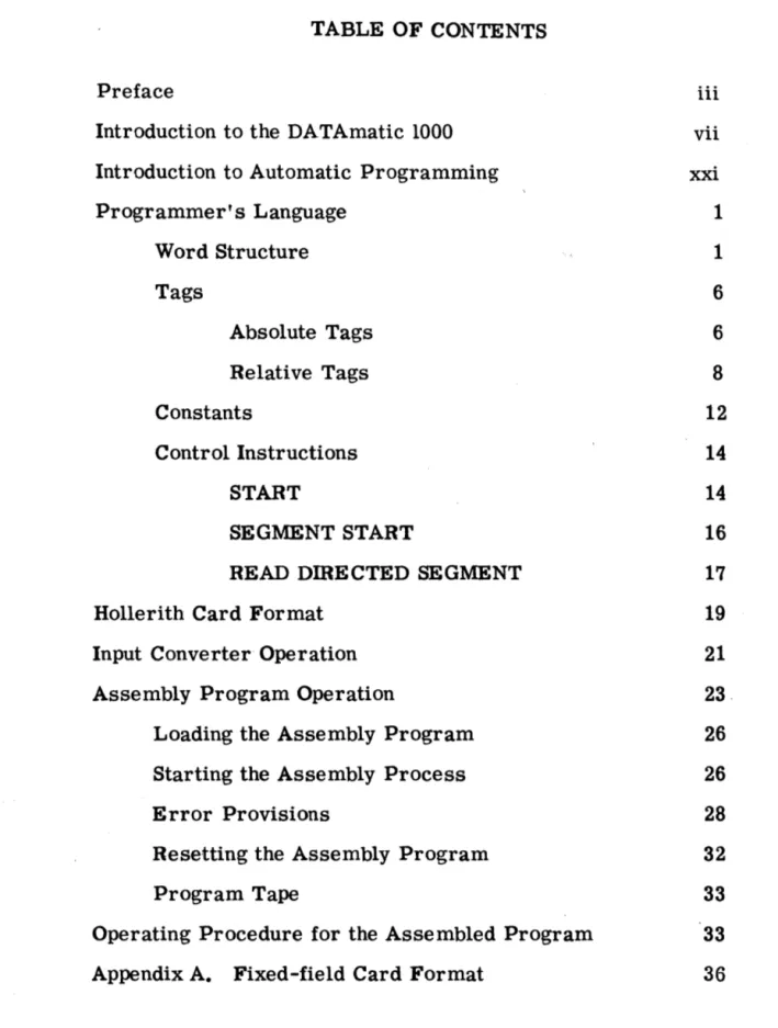
TABLE OF CONTENTS
Preface iii
Introduction to the DATAmatic 1000 vii
Introduction to Automatic Programming xxi
Programmer's Language 1
Word Structure 1
Tags 6
Absolute Tags 6
Relative Tags 8
Constants 12
Control Instructions 14
START 14
SEGMENT START 16
READ DmECTED SEGMENT 17
Hollerith Card Format 19
Input Converter Operation 21
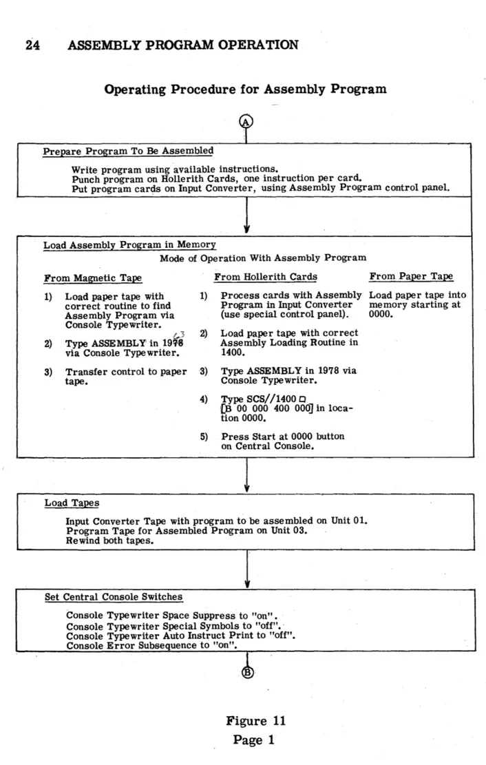
Assembly Program Operation 23 .
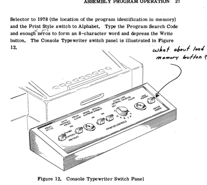
Loading the Assembly Program 26
Starting the Assembly Process 26
Error Provisions 28
Resetting the Assembly Program 32
Program Tape 33
Operating Procedure for the Assembled Program 33
INTRODUCTION TO THE DATAmatic 1000 vii
The DATAmatic 1000 is a high-capacity electronic data-processing system designed specifically for application to the increasingly complex problems and procedures required in modern business. The system incorporates significant new systems techniques as well as several basically new component developments. One of the primary features of the DATAmatic 1000 is its exceptionally large capacity to store in-formation on magnetic tape, coupled with its ability to feed informa-tion from ma~etic tape to the processing section and back to magnetic tape at a sustained rate of 60,000 decimal digits per second. In ad-dition, the operational speed of the processing section maintains full compatibility with this high speed of information transfer.
Two of the most cumbersome aspects of most business problems are sorting and file maintenance. The DATAmatic 1000 is equipped with an extensive and flexible set of instructions, designed specifically to excel in the performance of these functions and many others. These instructions may be automatically assembled into complete programs by the DATAmatic ABC-l Automatic Business Compiler. Thereafter, a task which is repeated daily or weekly is initiated simply by reusing the program from its storage on the program magnetic tape.
In the DATAmatic 1000, reliability is a prime consideration through-out every aspect of engineering and design. The design of electronic circuitry is highly conservative. Every transfer of information within
the sy~tem is carefully checked to insure that the information is
trans-ferred without alteration. In addition, all arithmetic and logical opera-tions are completely checked. All units of the system are constructed of easily replaced standard packages to facilitate maintenance. A system of marginal checking includes circuitry and a special program which may be run periodically to locate any package which should be
viii INTRODUCTION
A High-Speed Memory Amplifier package representative of the modular construction used throughout the DATAmatic 1000 system
Elements of the System
The system may be conceived functionally as comprising three main sections, the Input, Central Processor, and Output Sections, although its physical layout will generally not correspond with such a concep-tion. Data is initially fed into the Input Section in the form of punched cards. This section, which includes a Card Reader, an Input Con-verter, and one Magnetic File Unit, reads the data from the cards, translates it.into machine language, edits and arranges it into the desired format, and records it on magnetic tape.
INTRODUCTION ix
Typical Layout of a DATAmatic 1000 Electronic Data-Processing System
Central Console. The Central Processor reads data stored permanent-lyon magnetic tape, performs all manipulations of data, controls the sequence of functions performed, stores information temporarily while it is being processed and, after processing, stores it permanently on magnetic tape. By means of the Central Console, the operator may monitor the overall operation of the system. As needed, Magnetic File Units may be used by auxiliary equipment. Such action is con-trolled by switches.
The Output Section converts data from magnetic tape into either punched-card form or printed form, performing considerable editing in the process. The Model 1300 Output Converter, which feeds
x INTRODUCTION
Printer, depending on the quantitative requirements of the system for output information. One Magnetic File Unit may be considered a part of the Output Section.
Magnetic Tape Storage
The basic medium for the storage of information in the DATAmatic 1000 is magnetic tape. The particular tape used, the method of re-cording information on it, ~nd the tape-handling equipment have all been designed or selected to be mutually compatible and to provide high capacity, ease and speed of access to information, ultra-reliable storage and recovery of information, and maximum utilization of space on the tape.
Type VTR-179 magnetic tape has been selected for the DATAmatic 1000 because of its reliability and long life. This tape consists of a layer of iron oxide bonded to a tough, durable Mylar plastic base. A reel of
tape is three inches wide and 2700 feet long and can store over 37,000,000 decimal digits of information, the equivalent of data which would require 465, 000 punched cards.
Stored information is recorded on the magnetic tape in groups of mag-netized spots. The length rather than the strength of these spots is used to form a dot-dash code representing the encoded digits, letters, and symbols. This, the first of a series of unique reliability features, assures that variations in the recorded signal strength will not result in errors.
INTRODUCTION xi
reverse direction. The blocks not filled in a given direction of travel provide the space for starting and stopping the tape in that direction. As a result, informati.on is recorded on almost the entire area of the tape. Moreover, since the reversal of tape direction is accomlliished automatically, all of this information is written or read sequentially and the tape is positioned at its physical beginning at the conclusion of this process.
Information is recorded lengthwise to the tape in 31 channels, a system which greatly speeds the transfer of information and facilitates search-ing processes. Specifically, as many as ten tapes may be searched simultaneously, which means that the system is actually passing over 600, 000 decimal digits per second while seeking the particular item desired. The read-record head will write on the tape at the sustained rate of 60, 000 decimal digits per second and will recover this informa-tion at the same rate. The reading or searching operainforma-tions may be performed with the tape travelling either forward or backward.
The tape-drive mechanism and the read-record head are contained in the Magnetic Ffi.e Unit. An installation may include from four to one hundred Magnetic File Units, all directly connected into the system. They may be divided in any manner and at any time between the reading and recording operations. The volume of transactions and the com-plexity of operations govern the number of Magnetic File Units re-quired for a given system. Furthermore, these units may be added to or removed from the system at any time as these requirements vary.
xii INTRODUCTION
DATAmatic 1000 Magnetic File Units
from the Central Prooessor, reading data to the Central Processor, or reading data to a File Reference Unit. Also available is a File Switching Unit which increases the flexibility with which Magnetic File Units may be arranged into the various functional groups.
Input Section
INTRODUCTION xiii
The information which is read from the punched cards is translated into the language of the system and arranged in the format of the mag-netic tape by the Input Converter. In this process, it passes through two control panels and two temporary storage locations, providing great flexibility for transposition, duplication, and discarding of information. The operator manually sets an identifying . control number into the In-put Converter, which includes this number in the information to be
written on magnetic tape. The control number may then be written on the batch of cards which it represents, in case it is desired later to cross-reference these cards with their corresponding tape.
The encoded information is first arranged in a tOO-column format within the converter. In this conversion, any number of card columns may be duplicated provided that the total number of columns does not exceed tOO. Triplication of columns is not permitted. Thirteen conversion rules are available for the translation of punch code into machine code. Any single card column may be translated by anyone of these thirteen rules. The information is then translated into the final tape format, the contents of two punched cards being fed to each block on the magnetic tape. Several automatic checking features are built in to detect improperly punched cards or errors either in reading or in one of the conversion steps. The operator contr.ols the settings of a group of panel switches which direct the course of action that the machine is to follow in each of these situations.
xiv INTRODUCTION
Binary Notation
Information which is manipulated, stored, or communicated other than by electronic systems is generally written using 10 decimal digits, 26 alphabetic characters, and a ~umber of punctuation marks and other special symbols. Basic to the adaptation of information to electronic systems is the fact that such information can be written entirely in terms of two symbols, generally called zero and one. This presenta-tion is called binary notapresenta-tion and is analogous to the presentapresenta-tion of information in the more familiar Morse Code, in which the two symbols used are called dots and dashes. The symbols used in a binary nota-tion are called binary digits or bits. For example, the ten familiar decimal digits, 0 through 9, are represented in binary notation as follows:
0000
- 00101
- 50001 -
10110 -
60010 -
20111
- 7
0011
- 31000
- 80100
- 4
1001
- 9Bars will sometimes be placed over binary digits when there is some danger of confusing them with decimal zeros and ones.
INTRODUCTION xv
Central Proces.sing Section
The Central Processor has already been defined to include the Arithmetic and Control Units, the Input and Output Buffer Storage Units, the High-Speed Memory, the Magnetic File Units, and the Central Console. To-gether, these units contain the electronic elements and circuitry for high-speed performance of the stored programs.
The fast and reliable internal memory is composed of over 100,000 magnetic cores· and has a capacity of 24, 000 decimal digits. Access is in parallel for rapid readout of stored information. Processing of
data stored on magnetic tape is also enhanced by the inclusion of two Input and two Output Buffer Storage Units. These buffers, which are each capable of storing 744 decimal digits, permit a steady flow of
information to and from memory and enable the memory to read from one tape and write on another simultaneously.
\
The design of the Central Processor and the provision of certain special instructions are specifically aimed at the attainment of high sorting, merging, and file-maintenance speeds. Some examples of the speeds achieved are:
Sort - 60,000 decimal digits per second (equivalent to 750 fully punched cards per second).
Merge - 60,000 decimal digits per second.
File Maintenance - 600,000 decimal digits per second.
xvi INTRODUCTION
High-Speed·Memory section of the DATAmatic 1000 Central Processor
INTRODUCTION xvii
DATAmatic 1000 Central Console showing simplicity of layout achieved through functional design
A fundamental reliability feature of the system is the fact that each basic unit of information include s a check digit called the weight count. This
weight count is recomputed after each transfer of information within the system. The arithmetic comparison of the original and the re-computed weight counts is ~n extremely positive and economical means of verifying all internal information transfers, plus arithmetic and logical operations.
Output Section
xviii INTRODUCTION
either singly or together, depending on the quantity and speed require-ments of the application. These are the Model 1300 Output Converter which provides the required output to drive a standard card punch and/ or a standard 150-line-a-minute printer, and the Model 1400 High-Speed Output Converter which includes a special DATAmatic High-Speed
Printer capable of printing 900 lines per minute. As is the case in the Input Section, one or more Magnetic File Units are normally assigned to communicate between the Central Processor and the Output Converter.
Model 1300: The Model 1300 Output Converter reduces data stored on magnetic tape to a form acceptable to a standard 150-line-per-minute tabulator and/or a standard 100-card-per-minute card punch. The tabulator and card punch functions, governed by standard control panels, are preserved.
Information is read from magnetic tape to the converter in quantities of up to 192 decimal digits, 128 alphabetic characters, or equivalent. Each of these sets of data is processed individually and becomes the basis of one line of printed output and/or one 80-column punched card.
The data is then read into converter output storage through a code translator, controlled by a conversion control panel. There are 14 rules for the translation of machine language into standard punch card code.
The output storage section simulates 120 columns of punch-card data, in which form the information leaves the converter. Format arrange-ment and all other standard printout functions are governed in normal fashion by the control panels associated with the readout equipment. In the case of the card punch, the data is converted into the standard
INTRODUCTION xix
Model 1400: The Model 1400 High-Speed Output Converter oper-ates from a completely flexible tape format and performs a con-siderable amount of editing and format arrangement while preparing information to be printed at the rate of nine hundred 120-character lines per minute. In fact, the most complicated printed formats are obtained with a minimum amount of pre-editing required in the Central Processor. Special symbols and legend material can be emitted. Also the printing of certain parts of the form may be suppressed, dependent upon the contents of other data within the particular record. Further-more, the same output tape may be used for several different types of printing runs by wiring and using all of the control panels in the equipment. The ·sequence of information on magnetic tape need not ha ve any relation to the sequence of printing of information within a given line. It is, moreover, possible to scan a record on the tape several times, on each occasion deriving different combinations of data to be printed on a given form; data from the tape may be rejected or printed several times at will.
From the moment that information is read from the magnetic tape to the actual printing process, a complete train of information monitor-fng exists to preclude the possibility of printing erroneous information. This system includes a read-back signal from the actual printing ham-mer to the original stored information to verify the correctness of the character being printed in every column of the form.
xx INTRODUCTION
120 may be used during a given run. Two additional control panels are used to select the particular 120 print positions to be used and to perform further editing.
Integrated Checking
The weight count feature of the DATAmatic 1000, previously described, is an integrated checking system which verifies every information transfer, arithmetic and logical operation from the original conversion to machine language through the final production of printed or punched output. The weight count digit is originally computed and checked during the input conversion process. It is then recorded on tape, one such digit being an integral part of each basic unit of information and remaining with this basic unit throughout all of the operations of the system. Thereafter, recomputation and checking of weight count
verifies every transfer of information from tape to the Central Process-or, and all internal operations within the Central ProcessProcess-or, transfers from the Central Processor to tape, transfers from tape to the Output Converter, and Output Converter decoding processes. Each of these
INTRODUCTION TO AUTOMATIC PROGRAMMING xxi
Automatic programming routines aid in preparing programs for elec-tronic data-processing systems by replacing many repetitious manual tasks with automatic machine functions. Not only are time and money saved, but programming accuracy is greatly enhanced. In fact, the sheer volume of programming required by large data-processing ap-plications has made such routines a practical necessity. In order to illustrate how such" routines assist the programmer, it is necessary first to describe the steps associated with conventional program prep-aration and then to show the manner in which automatic programming can replace some of these steps or minimize the work associated with
them.
Manual Programming Procedure
The preparation of a program to perform a large-scale data-processing operation without the use of automatic programming can be broken down into these eight major steps:
(1) Analysis of the Operation (2) System Design
(3) Program Design (4) Coding
(5) Input Preparation (6) Checkout Planning (7) Checkout
(8) Program Operation
Step 1. Analysis of the Operation. In a data -processing operation, the machine processes a large quantity and a wide variety of data in order to produce· the required information. Therefore, before a
method of approach can be considered, the operation to be performed must be carefully analyzed. All of the specific inputs must be
xxii INTRODUCTION
estimated. The same consideration must be given to the required output information. This analysis is frequently made by means bf flow charts which show the interconnections and sequential relation-ships of these inputs, processes, and outputs.
Step 2. System Design. With the inputs, processes, and outputs of the operation clearly defined, it is possible to design a program-ming system. The initial task at this step is to specify the format of the data being ·processed at the input stage, the processing stages, and the output stage, i. e., the way in which the information will be punched on input cards, the format of the information on magnetic tape files, and the printed or punched output format. The procedure for operating the data -proce ssing system must also be considered;' tape changing during program operation, console operation, control panel wiring, and control information printed out at the operator's console all play an important role in the design of the system.
At this point, the preparation of the actual program begins. A block diagram is prepared which shows the logical steps that the input data must go through in order to produce the required out-put information and the sequence in which these steps are to be performed. This diagram consists of a series of blocks, one for each logical step, with lines connecting the blocks to indicate the sequence in which they are performed.
INTRODUCTION xxiii
Step 4. Coding. The programmer may now begin the coding process, that is, writing the instructions which will direct the
I
data -processing system to perform the functions indicated in each box of the programming flow diagram. Memory locations must be assigned to all program instructions and other data. However, prior to the actual start of coding, the method of opera-tion indicated by the block and flow diagrams should be evaluated and any changes which will improve the program should be intro-duced at this point.
Step 5·. Input Preparation. The coded program must be transcribed onto a medium which the data-processing system can read and trans-lated into a language which it can understand. This function is
accomplished by keypunc.h operators who transfer the information from the programmers' coding sheets onto standard aO-column punched cards. The Input Converter then writes the punched infor-mation on magnetic tape.
Step 6. Checkout Planning. Up to this pOint, the programming
system has been gradually broken down into a large number of steps, each of which is implemented by a few machine instructions. These instructions have been assembled in the proper sequence to perform the data-processing operation. After a program has been coded, steps must be taken to verify that it performs the desired functions. First, an overall checkout plan must be prepared; then the steps in the checkout process must be specified in detail.
Step 7. Checkout. The first part of the checkout process is to operate the program using specific controls prepared during step 6 as a part of the overall checkout plan. These controls permit
xxiv INTRODUCTION
must be tested with a variety of input data and it should be made to produce samples of all of the types of output information. There-fore, to conclude the checkout process, a simulation of the entire programming system must be performed on the machine.
Step 8. Program Operation. Each checked-out program requires operating instructions, scheduling information, and set-up plans in order to make the most efficient use of the machine. These instructions must specify the techniques necessary to get the input data into the machine, control the processing of the data, and pre-pare the required output information. They should also specify all of the special indications which are produced at the operator's console to increase the efficiency of program operation. To com-plete the documentation, a flow diagram and an annotated copy of
the program must be prepared.
Elements of Automatic Programming
A SSE MBL Y PROGRAMS: The purpose of automatic programming is to replace the routine portions of these eight steps with machine oper-ations. First of all, the language which the programmer uses differs from the language of the machine. Programmers work best with easily-remembered or mnemonic operation codes (e. g., ADD, BUB, MUL) and decimal numbers; electronic data-processing systems work with binary information. The translation from the mnemonic-decimal language of the programmer into the binary language of the machine is just the sort of task which high-speed data-processing systems do well. Not only is translation accomplished rapidly, but the results are error-free. Programs which perform this operation are usually called Assembly Programs.
COMPILERS: In the program design step, the blocks of the block
INTRODUCTION xxv
appears in several programs. Using manual programming procedures, the cOding and checkout steps must be repeated each time this block appears. However, much time can be saved in the flow diagramming, coding, and checkout of routines with identical blocks by having the person who first codes the block perform a few extra tasks to preserve the COding for other programmers Wishing to use it. Such reusable blocks are called subroutines. The routine task of duplication of cod-ing can be eliminated by extendcod-ing the Assembly Program so that sub-routines can be added to any program by a Single instruction. There-fore, by introducing subroutines into the programming system, all of the steps after System Design are effectively and automatically eliminated with respect to the subroutines. A program which is capable of
pro-cessing subroutines in this fashion is called a Compiler because it ~.~ ...• ~"''''''':D''k .... ~'<r>,~_"~~H~,,, .. _ _ _ _ compiles completely coded and checked-out subroutines into a program.
SUBROUTINE LffiRARY MAINTENANCE: .Subroutines, together with instructions for their use, . are stored on magnetic tape or on punched cards in what is called a Subroutine Library. A Compiler may be
supplemented by a program which automatically adds, deletes, or modi-fies subroutines in the Subroutine Library. This Library Maintenance Program, as it is generally called, relieves the program~er of another routine task.
xxvi INTRODUCTION
UTILITY ROUTINES: The automatic routines which have been
de-Be ribed assist in the preparation of programs. There is another
group of automatic routines which aid in the ch~ckout phase of pro-gram preparation. These are called Utility Routines.
In the checkout step, the programmer is assigned short periods of time on the machine. During these periods,. he must operate his program and obtain sufficient information to locate and analyze any errors it may contain. A listing of the contents of memory at var-ious stages of thisproceBB may provide the necessary information. The program which produces such a listing is called a Post Mortem .or Memory Dump Routine. These routines convert the contents of
memory from the binary form to the mnemonic and decimal language of the programmer.
Some types of errors are difficult to track down using the Post Mortem Routine. Under such conditions the programmer would like to know exactly what happens as each instruction is performed in the region of the error. This could be accomplished manually by using the Central Console to examine the affected memory locations after per-forming each instruction. However, this process is extremely wasteful of machine time. A program called a Tracing Routine per-forms this function automatically at high speeds. The Tracing Rou-tine produces a listing of the instructions performed in the sequence
in which they were performed and for each instruction specifies the contents of the affected memory locations.
Data-processing systems work with information stored on magnetic tape; therefore, certain procedures are necessary to insure
INTRODUCTION xxvii
SECTION I - DATAmatic 1000 ASSEMBLY PROGRAM
The Assembly Program is a routine which translates programs from the alphabetic and decimal language of the programmer to the binary language of the computer. The programmer writes the instructions of his program using three -character mnemonic operation codes. Each word being coded is assigned a tag which indicates its location in memory and which may be used within instructions to refer to the . . word. A tag may be the absolute address of a specific location in the High-Speed Memory or it may be a relative tag which designates an address in relation to a specific memory location. Control information required by certain instructions, i. e., number of shifts, number of words transferred, or tape identification codes, is specified in decimal numbers. The Assembly Program processes programs written in this form, translating the mnemonic operation codes to the proper internal codes, assigning memory locations to relative tagsJ
converting decimal numbers to the appropriate binary configurations, and producing a copy of the program in machine language on magnetic tape.
1
SECTION I - THE ASSEMBLY PROGRAM
PROGRAMMER'S LANGUAGE
Table I, pages 2-5, contains a list of the symbolic instructions which may be used with the Assembly Routine. All DATAmatic 1000 instruc-tions are included in this list. The complete specificainstruc-tions for the instructions are given in Section I of the DATAmatic 1000 Programming Manual. There are special instructions for interpreting three kinds of constants: signed numeric words consisting of a plus or minus sign and eleven hexadecimal digits; unsigned numeric words containing twelve hexadecimal digits; and alphanumeric words containing eight Latin letters, decimal digits, or special symbols.
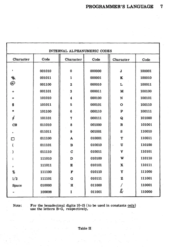
Table II, page 7, contains a list of 6 -bit interpretations of all codes used as input to the Assembly Program. These include letters, numbers, hexadecimal digits, and special symbols. When a 4-bit interpretation of a code is required, as in numeric words and instructions, the Assem-bly Progran'l makes the necessary conversion.
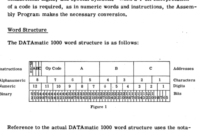
Word Structure
The DATAmatic 1000 word structure is as follows:
Instructions
Alphanumeric Numeric Binary
Op Code A B
Figure 1
C Addresses
Characters Digits
Bits
2 PROGRAMMER'S LANGUAGE
SUlI4MARY OF DATAmatic 1000 INSTRUCTIONS
INSTRUCTION TYPE Add Subtract Multiply Divide Shift Left (preserving sign) Shift Right (preserving sign) Shift Left (with sign)
Shift Right (with sign)
Substitute
Transfer In (A Buffer) (B Buffer) (Same Buffe r) (Different Buffer) Transfe r In Bypass
(A Buffer) (B Buffer) (Same Buffer) (Different Buffer) Double Transfe'r-and
Select (A Buffer) (B Buffer) (Same Buffer) (Different Buffer)
INSTRUCTION FORM
ADD/X/Y/Z CJ
SUB/X/Y /Z t:l
"-MUL/X/Y/Z C1
DIV /X/y/Z CJ
SLP /X/nN/Z CJ
SRP /X/nN/Z p
SLW
IX/n{~}z
0SRW
IX/n{$yz
0SST/X/Y/Zo
TIA/X/N/S CJ
TIB/X/N/SD TIS/X/N/S CJ
TID/X/N/S CJ
TBA/X/N/S 0
TBB/X/N/S Cl
TBS/X/N/S CJ
TBD/X/N/S CJ
, DTA/X/N/m/S 0
DTB/X/N/m/S C1
DTS/X/N/m/S 0
DTD/X/N/m/S Cl
FUNCTION
Add the contents of X to the contents of Y and store in Z. X and Y remain unchanged. Sub-sequence to 1988 in case of overflow.
Subtract the contents of Y from the contents of
X and store in Z. X and Y remain unchanged. Subsequence to 1988 in case of overflow. Multiply the contents of X by the contents of Y and store the rounded high-order product in Z •. Store the low -orde r product with 5 added to the high-digit position in 1995.
Di vide the contents of Y by the contents of X and store in Z. The remainder is stored in 1995.
Shift the contents of X, n numeric places left and store in Z. Sign character and the con-tents of X remain unchanged.
Shift the contents of X, n numeric places right and store in Z. Sign character and the con-tents of X remain unchanged.
Shift the contents of X, nN (n Numeric), nA (n Alphabetic), or nT (n Two-bit) places to the left and store in Z. Sign character is included in the shift. Contents of X remain unchanged. Shift the contents of X, nN (n Numeric), nA (n Alphabetic), or nT (n Two-bit) places to the right and store in Z. Sign character is included in the shift. Contents of X remain unchanged. Insert into Z, the bits of (X) for which there is a 1 in the corresponding bit posit~ons of (Y). Leave unchanged the bits of (Z) for which there is a 0 in the corresponding bit positions of (Y). Transfer N words from the specified buffer section into N consecutive HSM locations begin-ning at location X. Subsequence to S.
Bypassing the interlock, transfer N words from the specified buffer section into N consecutive HSM locations beginning at location X. Subse-quence to S.
1) Transfer N words to Output Buffer from con-secutive HSM locations beginning at X. 2) Replace these N words by N words from the
specified Input Buffer Section.
3) Use the mth word and the Extractor Register to form the selection digit. Add digit to units digit of S and Subsequence to the modified address.
4) Store the instruction in Select Order Register (1994).
For complete details of DATAmaticlOOO instructions, see the Programming Manual, Sec. I
INSTRUCTION TYPE
Double Transfer and Select--Bypass
~A Buffer) B Buffer) (Same Buffer) (Different Buffe r) Transfer and Select
(A Buffer) (B Buffer) (Same Buffer) (Different Buffer) Transfer and Select --Bypass
(A Buffer) (B Buffer)
~same Buffer) Different Buffer) Internal Select
Transfer Out
Transfer Internally
Twin Transfer
Transfer and Subsequence Call Read Forward
Read Backward
Read Forward, Key Channel
Read Backward, Key Channel Print Alphabetic
INSTRUCTION FORM
DBA/X/N/m/S CI
DBB/X/N/m/S Cl
DBS/X/N/m/S t:l
DBD/X/N/m/S t:J
TSA/x/NI m/S t:J
TSB!X!N!m!S Cl
TSS/X/N/m/S c
TSD/X/N/m/S 0
BSA/X/N/m/S c BSB/X/N/m/S c
BSS/X/N/m/S CJ
BSD/X/N/m/S t:l
ISL/X/Y /S t:I
TXO/X/N/S c
TXI/X/Z/N CJ
TTX/X/Y/Zc
TXS/X/Z/Sc
RF A/T / e /S t::J
RFB/T/e/s t:J
RFD/T/e/S CJ
RBA/T /e/s t:J
RBB/T/e/s 0
RBD/T/e/S c
RFK/T/c/s C
RBK/T/e/s 0
PRA/X/e/S CI
PROGRAMMER'S LANGUAGE 3
FUNCTION
Same as Double Transfer and Select except that the interlock is bypassed.
Same as Double Transfer and Select except that step 1, the transfer of words to the Output Buffer, is omitted.
Same as Transfer and Select except that the interlock is bypassed.
Use X and Y to form a selection digit. Add this digit to units digit of S and Subsequence to the modified address.
Transfer N words from consecutive HSM loca-tions beginning at X to the Output Buffer. Subsequence to S.
Transfer N words from consecutive HSM lo-cations beginning at X to consecuti ve HSM Locations beginning at Z.
Transfer the word in the Select Order Register
(1994) to X and the word at Y to Z.
Transfer the contents of X to Z. Subsequence to S.
Read next block in forward direction on Tape T into the
A = A Buffer B = B Buffer
D = Different Buffer.
Change Sequence Register to C. Subsequence to S.
Read next block in backward direction on Tape
T into the A = A Buffer B = B Buffer
D = Different Buffer.
Change Sequence Register to C. Subsequence to S.
Put key channel of Tape T in read state and satellite channels in write state. Read Key Channel of next block in forward direction into B Buffer. Change Sequence Register to C. Subsequence to S.
Same as Read Forward, Key Channel except that the tape is moved backward.
Print contents of X as 8 alphanumeric charac-ters on the Console Typewriter. Change Sequence Register to C. Subsequence to S.
4 PROGRAMMER'S LANGUAGE
INSTRUCTION TYPE
Print Numeric
Write Forward
Write Forward, except Key Channel
Search Forward, Reading Search _Backward, Reading Search Forward, Writing Search Backward, Writing Rewind Ta:pe
Switch to First Half
Switch to Second Half
INSTRUCTION FORM
PRN/X/C/S 0
WFA/T/C/SO
WFP/T/C/Sc
SFR/T/C/S 0
SBR/T/C/S 0
SFW/T/C/Sc
SBW/T7c/s Cl
REW/T/C/SO
SWF/T/C/S Cl
SWS/T/C/S 0
Less Than Comparison, LCN/X/Y/C Cl
Numeric
Inequality Comparison, ICN/X/Y/C 0
Numeric
Less Than Comparison, LCA/X/Y/Cc Alphabetic
Inequality Comparison, ICA/X/Y/C c
Alphabetic
First Key Comparison FKC/X/Y/CO
Second Key Comparison SKC/X/Y/C 0
Pass
Sequence Change
PSSo SCS/i/C/SC
FUNCTION
Print contents of X as 12 hexadecimal charac-ters on Console Typewriter. Change Sequence Register to C. Subsequence to S.
Put key and satellite channels in write state. Write one block on Tape T. Change Sequence Register to C. Subsequence to S.
Put key channel in read state and satellitp channels in write state. Write one block. Change Sequence Register to C. Subse~uence
to S.
Put key and satellite channels in read state. Search one block forward. Change Sequence Register to C. Subsequence to S.
Same as in Search Forward, Reading except that tape moves in backward direction. Put key channel in read state and satellite channels in write state. Search forward one block. Change Sequence Register to C. Sub-sequence to S.
Same as in Search Forward. Writing except that tape moves backward.
Rewind Tape T. Change Sequence Register to C. Subsequence to S.
Position tape T to read from the first logical half of the tape. Change Sequence Register to C. Subsequence to S.
Same as SWF except tape T is positioned to read from the second logical half.
If contents of X is numerically less than or equal to contents of Y, change Sequence Reg-ister to C.
If contents of X is not numerically equal to contents of Y, change Sequence Register to
C.
If contents of X is alphabetically less than or equal to contents of Y, change Sequence Register to C.
If contents of X is not identical to contents of Y, change Sequence Register to C. Transfer conZ§.J>f first key to X. If con-tents of X is rt'han or equal to contents of Y, change Sequence Register to C. Tape number is units digit of X.
Transfer contents of second key to X. If con-tents of X is less than or equal to contents of Y. change Sequence Register to C. Tape
number is units digit of X.
Go to Sequence Register for next instruction. Change the Sequence Register to C. Subse-quence to S. i may contain up to three numeric digits.
PROGRAMMER'S LANGUAGE 5
INSTRUCTION INSTRUCTION
TYPE FORM FUNCTION
Branch and Return BAR/X/C/Se Store in X an instruction to change the Sequence Register to its present reading. Subsequence to S. Change the Sequence Register to C. Stop STOP/i/S 0 Unconditional stop. Subsequence to S. i may
contain up to three numeric digits. ~ Optional Stop OST/i/d/Sc Stov j f spgeUiea BI eakpoint Swttch is 9~J.
Subse-quence to S. i may contain upto 3 numeric digits.
SUMMARY OF DATAmatic 1000 CONSTANTS
CONSTANT TYPE CONSTANT FORM FUNCTION
Alphanumeric Constant A/Constant c Assemble as alphanumeric constant with the leftmost character in the leftmost position of
the word.
Unsigned Numeric U/u/Constant c Assemble as unsigned numeric constant with the digit position to the left of the decimal point placed in the uth digit position of the word.
Signed Numeric N/n/Constant c Assemble as a signed numeric constant with the digit position to the left of the decimal point placed in the nth digit position of the word.
If no sign appears, a + sign will be inserted.
SUMMARY OF ASSEMBLY PROGRAM CONTROL INSTRUCTIONS
INSTRUCTION TYPE Start
Segment Start
Read Directed Segment
Tag Assignment
INSTRUCTION FORM START/i/s/Y C
~ (JOtp~
,I"
SEGMENT. START/J3 (::I
RDS/
f~}/T/S/Y
cTAG/X/nc
FUNCTION
i is Program Search Code, a maximum of 8 alphanumeric characters; s is Segment Number, 2 digits; Y is starting location of program in absolute.
s is Segment Number, 2 digit's'~, 1
B or F determines read direction on Pro-gram Tape. T is tape drive of ProPro-gram Tape. s is Segment Number, 2 digits. Y is Starting Location after segment has been read in.
Defines the stem, X, by giving it a value, n. This value will be added to the decimal digits following X when it is used. X may have the form RS or R.
Table I (Page 4 )
s-Jo,.
,..#B,..w--pO'"'' .... '
~r~.I" . . ~t;. fI • .,. d
1:S 6",. .9 foP u",c.",d. i#d::.$
~ ";-.C~'fI cI
d.r:7-6 PROGRAMMER'S LANGUAGE
The basic structure of a word in the language of the Assembly Routine is:
Op Code/Zone 1/Zone 2/ •••••• /Last Zone c , where
(1) Op code is the mnemonic code used to specify the machine command, i.
e.,
ADD, SUB, TIS, etc.,(2) Zone 1 •••••• Last Zone are the parameters necessary to specify the complete instruction,
(3) andcis a special symbol used to denote the end of a word.
For example, TIB/1300/16/1800cinstructs the computer to transfer in 16 words from the B Buffer and store them in consecutive locations beginning ,with location 1300, then make a subsequence call to 1800.
All zones are decimal, even those which are binary in machine language. The Assembly Program makes the conversion.
Tags
Each word is "tagged" to indicate its location in memory. The tag of a word is called an Identification Tag. Every word has an identification tag. A tag used within a zone to refer to another word is called a
Zone Tag. The distinction applies only to the use of the tag; the same tag is an identification tag for the word it labels and a zone tag in the instruction which refers to the labelled word.
Any identification or zone tag referring to a location in memory con-tains four alphanumeric characters. The two rightmost characters of
a tag must be decimal (00-99). The type of alphanumeric characters in the first two positions ofa tag determine whether the address is absolute or relative. Both types of tags may be used in the same
pro-gram and any number of combinations of acceptable tags may be used.
PROGRAMMER'S LANGUAGE 7
INTERNAL ALPHANUMERIC CODES
Character Code Character Code Character
, 001010 0 000000
J
~ 001011 1 000001 K
@ 001100 2 000010 L
+ 001101 3 000011 M
= 101010 4 000100 N
$ 101011 5 000101 0
* 101100 6 000110 P
V- 101101 7 000111 Q
CR 011010 8 001000 R
.
011011 9 001001 S0 011100 A 010001 T
( 011101 B 010010 U ) 011110 C 010011 V
: 111010 D 010100 W
, 111011 E 010101 X
% 111100 F 010110 y 1/2 111101 G 010111 Z
Space 010000 H 011000 /
-
100000 I 011001&
Note: For the hexadecimal digits 10-15 (to be used in constants only) use the letters B-G, respectively.
Table II
8 PROGRAMMER'S LANGUAGE
Addresses 1980-1999 are special addresses whose functions are described in Table ITI, pages 10 - 11. Address 1978 has a special function described under "Starting the Assembly Process. " p~ge 26. In absolute coding, the non -significant digits. of an address need
-.
not be written. Therefore, 492 is equivalent to 0492, 39 is equivale~t
to 0039. If a zone is all zeros, no digits need be written in it. Figure 2 shows some examples of absolute coding.
Absolute Identification Tags
1001 1002 1003 1004
Absolute Zone Tags
1
r
scsi /1542/1593 0
TXS/1394/492 c BAR/156/39 c
WFA/9 c
This is equivalent to
Absolute Identification Tags
1001 1002 1003 1004
Absolute Zone T\S
J~
SCS/0000/1542/1593 CJ
TXS/1394/0492/0000 a '
BAR/O 156/0039/0000 c
WF A/0009/0000/00000
Figure 2
There are two types of RELATIVE TAGS:
(1) The first type has the form ~ddd, where R is a digit greater than one or
a
letter which identifiesa
relative counter, and' each d is a decimal digit. These tags permit as many as 1000 words to be included within a single relative counter. All tags of this type having the same first digit are related to the same address.(2) The. second tag form is RSdd, in which R can be any letter or number, S must be a letter, and each d is a decimal digit.
I
This tag form permits up to 100 words to be included within
-PROGRAMMER'S LANGUAGE 9
each relative counter. All tags having the fame ~t two characters
c-iI
are related.
In relative coding, the four digits of an address must be written. The R or RS portion of a tag is called its stem. Before a relative tag is
' " , ~
used, the programmer must write a TAG/X/n CJ instruction which
defines the stem, X, by giving it a value, n. The value of a stem is added to the decimal digits which follow it when used in the program. If, for some reason, the same stem is defined more than once in a pro-gram, each definition given will be used by the Assembly Program until the next one appears. Otherwise, the value of a stem remains fixed throughout the entire program. If the stem is not defined at all before a tag using the stem appears, a
TAG ILLEGAL
error will be printed on the Console Typewriter (see Table IV, pages 30 _
31). If the address which results from adding the decimal digits of
a tag to. the value of the stem is greater than 1999, a TAG
ILLEGAL
error will be printed. Figure 3 shows SOILe examples of relative coding.
TAG
Instructions
Instructions in relative code
Same instructions in absolute code
Stem Value Assigned _______ ~ Stem
~
\l
TAG/C/4 CJ
TAG/5E/130 0
TAG/4D/98 a
{
TAG/ AB/50 CJ
Identification Zone Ta s
~ { _ 4D02 4D03 4D04 { 0100 0101 0102
Figure 3
ADD/ AB05/C114 AB08D SLW/C104/3N/5E01 0
TXS/5E01/C115 0
ADD/0055/0118/0058 Cl
SLW/0108/3N/0131 0
10 PROGRAM1.v.tER'S LANGUAGE
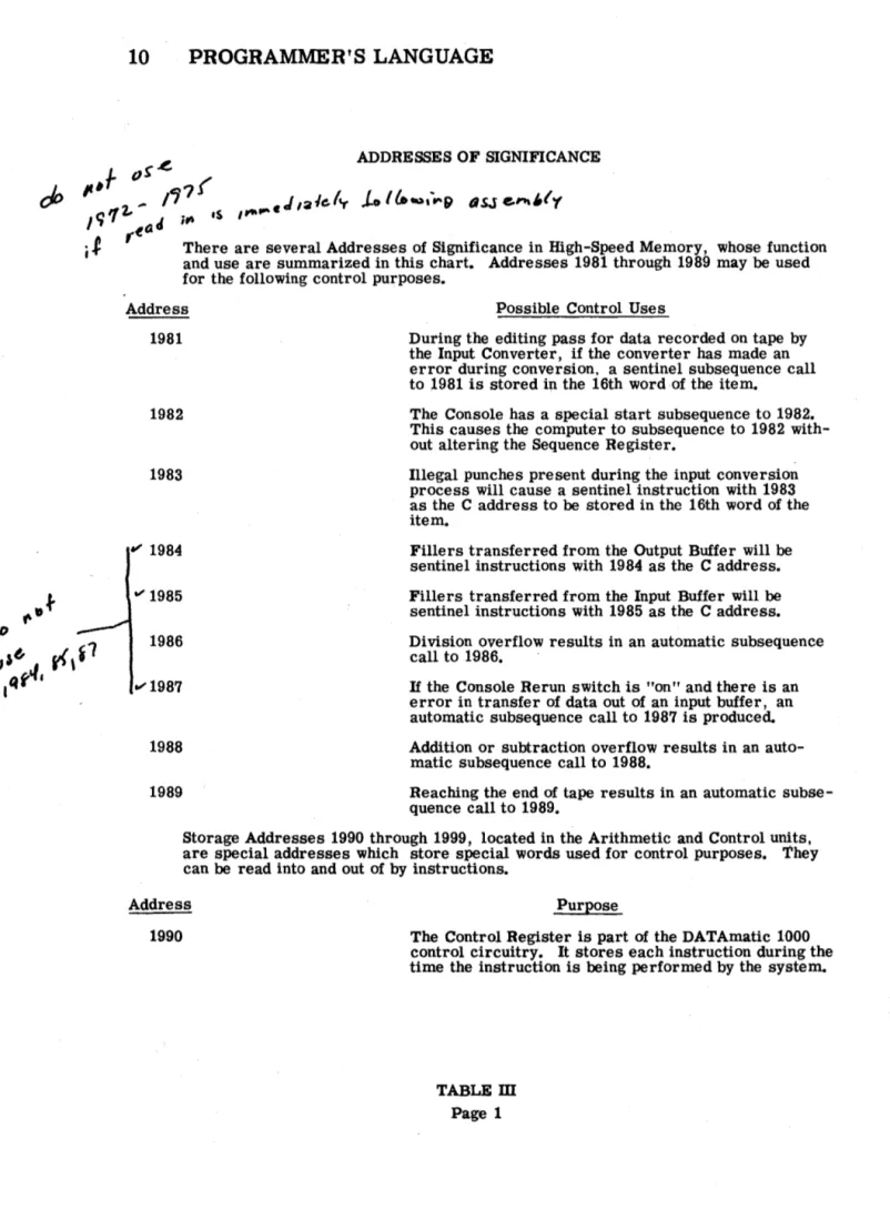
ADDRESSES OF SIGNIFICANCE
There are several Addresses of Significance in High-Speed Memory, whose function and use are summarized in this chart. Addresses 1981 through 1989 may be used for the following control purposes.
Address Possible Control Uses
1981 During the editing pass for data recorded on tape by the Input Converter, if the converter has made an error during conversion, a sentinel subsequence call to 1981 is stored in the 16th word ·of the item.
1982 The Console has a special start subsequence to 1982. This causes the computer to subsequence to 1982 with-out altering the Sequence Register.
1983
~ 1984
1986
1988
1989
Illegal punches present during the input conversion process will cause a sentinel instruction with 1983 as the C address to be stored in the 16th word of the item.
Fillers transferred from the Output Buffer will be
sentinel instructions with 1984 as the C address. Fillers transferred from the Input Buffer will be
sentinel instructions with 1985 as the C address. Division overflow results in an automatic subsequence call to 1986.
If the Console Rerun switch is "on" and there is an error in transfer of data out of an input buffer, an automatic subsequence call to 1987 is produced. Addition or subtraction overflow results in an
auto-matic subsequence call to 1988.
Reaching the end of tape results in an automatic subse-quence call to 1989.
Storage Addresses 1990 through 1999, located in the Arithmetic and Control u~ts.
are special addresses which store special words used for control purposes. They can be read into and out of by instructions.
Address Purpose
1990 The Control Register is part of the DATAmatic 1000 control circuitry. It stores each instruction during the time the instruction is being performed by the system.
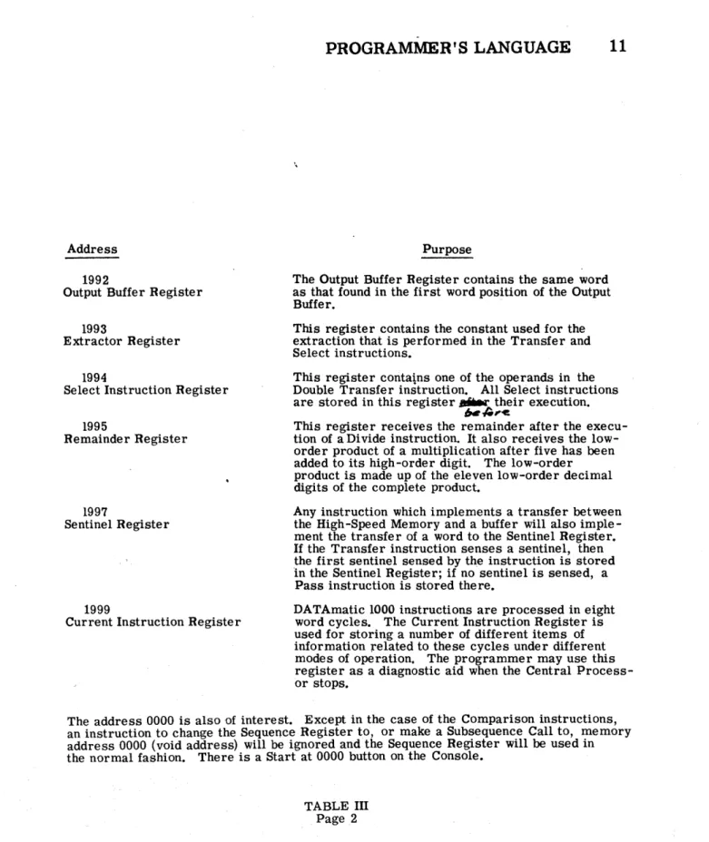
Address
1992
Output Buffer Register
1993
Extractor Register
1994
Select Instruction Register
1995
Remainder Register
1997
Sentinel Register
1999
Current Instruction Register
PROGRAMMER'S LANGUAGE 11
Purpose
The Output Buffer Register contains the same word as that found in the first word position of the Output Buffer.
This register contains the constant used for the extraction that is performed in the Transfer and Select instructions.
This register contains one of the operands in the Double Transfer instruction. All Select instructions are stored in this register ... their execution.
""',c.
This register receives the remainder after the execu-tion of a Divide instrucexecu-tion. It also receives the low-order product of a multiplication after five has been added to its high-order digit. The low-order product is made up of the eleven low-order decimal digits of the complete product.
Any instruction which implements a transfer between the High-Speed Memory and a buffer will also imple-ment the transfer of a word to the Sentinel Register.
If the Transfer instruction senses a sentinel, then the first sentinel sensed by the instruction is stored In the Sentinel Register; if no sentinel is sensed, a Pass instruction is stored there.
DATAmatic 1000 instructions are processed in eight word cycles. The Current Instruction Register is used for storing a number of different items of information related to these cycles under different modes of operation. The programmer may use this register as a diagnostic aid when the Central Process-or stops.
The address 0000 is also of interest. Except in the case of the Comparison instructions, an instruction to change the Sequence Register to, or make a Subsequence Call to, memory address 0000 (void address) will be ignored and the Sequence Register will be used in the normal fashion. There is a Start at 0000 button on the Console.
12 PROGRAMMER'S LANGUAGE
Note that the TAG instruction has no identificatiQn tag. TAG instruc-tions do not get assigned a place in memory. They are only for use by the Assembly Program. It should also be noted that in assigning tags,
-~he , programmer must take care to assure proper allocation of the Key
.. ~
<?omparison instructions and the Select instructions. ~ .. ~!he Key
e
o~-~ison"iristrB£ElonsLthe units digit of the A address des~gnates th~ ...
pIagnetjc tape address code. The value assigned to the stem, there-fore, must provide selectiOn of the proper magnetic tape information. The C address of the Select instructions is incremented by the digit generated by the instruction. Since a carry occurs if the sum exceeds nine and an error occurs if it exceeds nineteen, care must also be take-n in assigning a place in memory to the word specified by the C address.
Constants
In the discussion that follows, the words "alphanumeric character" are used to denote any of 56 Latin letters, decimal digits, and special sym-bols which are represented by 6-bit binary codes in the DATAmatic 1000 (see Table IT). Similarly, "hexadecimal" is used to denote any of the sixteen characters (ten decimal digits and six special symbols called hex B, C, D, E, F, and G) which represent the sixteen possible group-ings of a 4-bit binary code.
There are three methods of specifying constants (see Table I).
010010
PROGRAMMER'S LANGUAGE 13
The exact bit structure for this word is (see Table II for translation) ,
1001QO 010010 000100 000001 000000 000000 000000
(2) Signed numeric constant: N/n/Constant CJ. A signed numeric constant consists of a plus or minus sign, a max-imum of eleven hexadecimal or decimal digits in 4 -bit groups, and an indicator (decimal) point. The sign is put in the normal sign position (bits 52-49). If the sign is not written, a plus sign is put in the sign position. The charac-ter to the left of the indicator point is put in the "nth" digit .\-~ position (see Figure 1). If no indicator point appears in
f
~
\~ ~l;..
the number, the rightmost character of the constant is stored in the "nth" digit position of the word. For example,N/5/ + 207. 56 0
N/7/ - 12454 0
gi ve respectively,
1+10101010 \2101715161010
I -
11
I
2 1
4I
5
I
4I
0 1 0
-I
0
I
0
I
0
I
0
(3) Unsigned numeric constant: U/u/ConstantCl. The unsigned numeric constant contains a maximum of twelve hexadecimal or decimal digits stored in 4 -bit groups and an indicator (decimal) point. The character to the left of the indicator point is put in the "uth" digit position. If no indicator point appears in the number, the rightmost character of the constant is stored in the "uth" digit position of the word (see Figure 1). For example,
U/1/0 CJ
14 PROGRAMMER'S LANGUAGE
give, respectively,
10101010101 0
I
0
I
0
I
0
I
0 101 0
I
I
0
I0
I
0
I0
I0
I0
I0
I
10
1 8I
5 I1
I
51
Any constant that is neither wholly numeric nor wholly alphabeticmust be reduced to one of the three constant forms available by referring to Table
n.
Any configuration of bits in a word may be expressed as an unsigned numeric constant.Control Instructions
In order that the Assembly Program produce the program desired, certain control information must be furnished by the programmer.
The ~r Assembly Program control instructions provide the pro-grammer witIi a method for specifying this information. The TAG instruction, previously described, governs the placing of the operat-ing program in the memory. The START and SEGMENT START instructions serve to identify the beginning of a program or segment; respectively. The READ DmECTED SEGMENT (RDS) instruction facilitates the automatic interconnection of parts of a program. Detailed descriptions of the control instructions follow.
START/i/s/Y Cl
i-Program Search Code s - Segment Number
Y - Starting Location of program in absolute.
The- START instruction must be the first card of a program. A card with a modified START instruction must be punched each time
.-
--the program is reassembled (modified). This card will replace --the
' - . < .
-previous SyABT card. The START instruction is used to set up the
PROGRAMMER'S LANGUAGE 15
The program identification or Program Search Code appears in the first zone of the START instruction. The Program Search Code may contain a maximum of eight alphanumeric characters which may be separate and distinct from the Program Identification and Modification
-= ... •
Code specified in columns 1-7 on the punched cards (see Figure 5, page 19 ). However,
it
is recommended that the 5 -character Pro-gram Identification followed by the highest Modification Code used on a card in the program be used as the Program Search Code. ~program must have its own unique Program Search Code. It is used to search for the assembled program on the Program Tape. The ~
Program Search Code, the information in columns 1-7 on the card, and the segment number are printed on the Console Typewriter at the start of the assembly of each program.
A segment is a portion of a program. A program may be divided into segments because it is too large to be stored in the High-Speed Mem-ory at one time and/or because the programmer desires to separate the logical portions of his program. The segment number, s, is two digits. If the program is all in one segment, the segment num-ber is 01. The START instruction serves the same purpose for the first segment of a program as the SEGMENT START does for all the others.
The tag of the starting location of the program must be specified in absolute. When the assembled program is read into memory, the Sequence Register is set at this starting location, which is printed on the Console Typewriter as
BEG ----.
16 PROGRAMMER'S LANGUAGE
J
J GO tJI/1t#l PROGF"tl
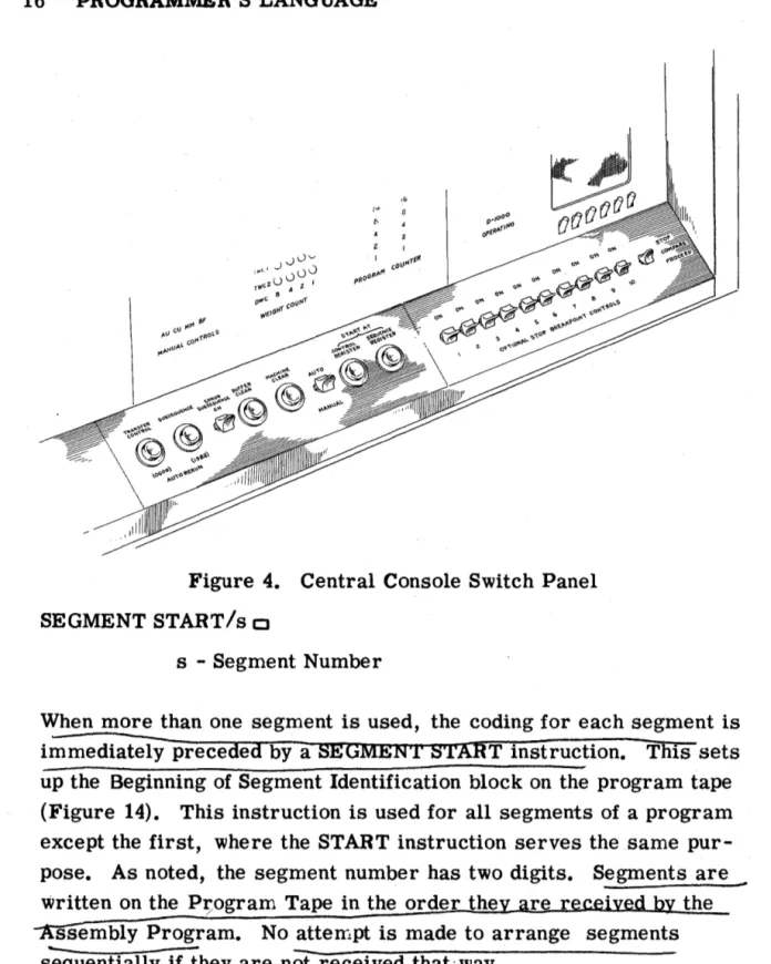
Figure 4. Central Console Switch Panel
SEGMENT START/s c:J
s - Segment Number
When more than one segment is used, the coding for each segment is immediately preceded by a SEGMEN'!' START instruction. This sets up the Beginning of Segment Identification block on the program tape (Figure 14). This instruction is used for all segments of a program except the first, where the START instruction serves the same pur-pose. As noted, the segment number has two digits. Segments are ~
written on the P;ogram Tape in the order the the
ssembly Program. No atterrlpt is made to arrange segments s'equentially if they are nOt received that'way.
'PROGRAMMER'S LANGUAGE 17
READ DmECTED SEGMENT: RDS/
{~}
/T/s/Ya
The RDS instruction is an optional instruction. H written in the pro-gram at the point where another segment is needed, the Assembly Program will automatically insert a routine during assembly which will search for and read into memory the segment indicated and transfer control to the address indicated. This instruction has an identification tag and the next 35 locations in memory must be left empty. The routine generated is placed in these locations by the Assembly Program and these locations must be avoided by the pro-grammer desiring to make use of the RDS instruction. Locations
-1972-1977 a~e used durin!-execution of the RDS instruction and, therefore, cannot contain information to be preserved from one seg-ment to another.
The first zone indicates whether the segment needed may be found by reading backward (B) or forward (F) on the Program Tape. If, for some reason, this is not known, the inserted routine will search forward, then backward if necessary. The programmer, however, generally knows the direction of search. Tape number is indicated by two digits in zone 2 of the RDS instruGtion. This is the tape drive of the Program Tape when the assembled program is run. ~ote that if the Assembly ,Program is used to operate the assembled program immediately after assembly, the Magnetic File Unit is 03. Zone 3 contains two digits to indicate the segment desired. If either zone 2
or 3 is missing, the words .- J1
if
ILLEGAL
d-
ted
seq J'1'1 e10 I ;re c
RDS • ~eea .
are printed on the Console Typewriter and the instruction is not pro-cessed. The last zone contains the starting location after the segment has been read into memory.
18 PROGRAMMER'S LANGUAGE
BEG ----.
The machine will stop after printing this out if Console Breakpoint Switch 1 is set (Figure 4). If no starting location is given, the words
NO BEGIN
are printed on the Console Type writer, the machine stops uncon-ditionally a~d the programmer is responsible for restarting his program. If, for some reason, the segment cannot be found,
NO SEG
--is printed and the machine stops. If this RDS instruction is not used in a program having more than one segment, the programmer assumes the responsibility for searching for and reading into mem-0ry his own segments as needed.
Once the proper segment has been located on the program tape, it is only necessary to read in a word and subsequence to it. This word causes the read-in of the words following it which are in con-secutive locations. At the end of each block, there is a sentinel subsequence call to 1984 or 1985. Hence, these locations must be loaded with appropriate instructions. For the first segment written on tape, these locations contain a Sequence Change instruction to .---1972. A Read instruction with the proper tape number must,
fue~efore, be stored in 1972 for automatIc read-in. The word stored on tape by the Assembly Program at the end of each segment is a subsequence call to 1980. This word is read into memory and per-formed when the rest of the segment is in memory. Proper- sequenc-ing of instructions may be effected by loadsequenc-ing 1980 with an instruction
.
which transfers control to the location of the first instruction to be
performed after the segment is in memory.
~t
t.0 ;
...
q~-{
. . .tII °i
0 . .
...
O~00000
1 2 3 4 5 6 7
1 11 1 1 1 t
22222 22 3 333 3 33
44444 44 55555 55 66666 66
7 7 777 77
88888 88 99999 99
I 2 3 4 5 6 7
HOLLERITH CARD FORMAT 19
0011 is:
1972 RFD/03 CJ
1973 TIS/1975/1/1975 0
1974
scsi
/1973 CI1975 CJ (Place for control word)
1976 A/BEG@OOll Cl
1977 OST//10
1980 PRA/1976/0011/1977 CJ
1984 SCS//1972 [J
1985
scsi
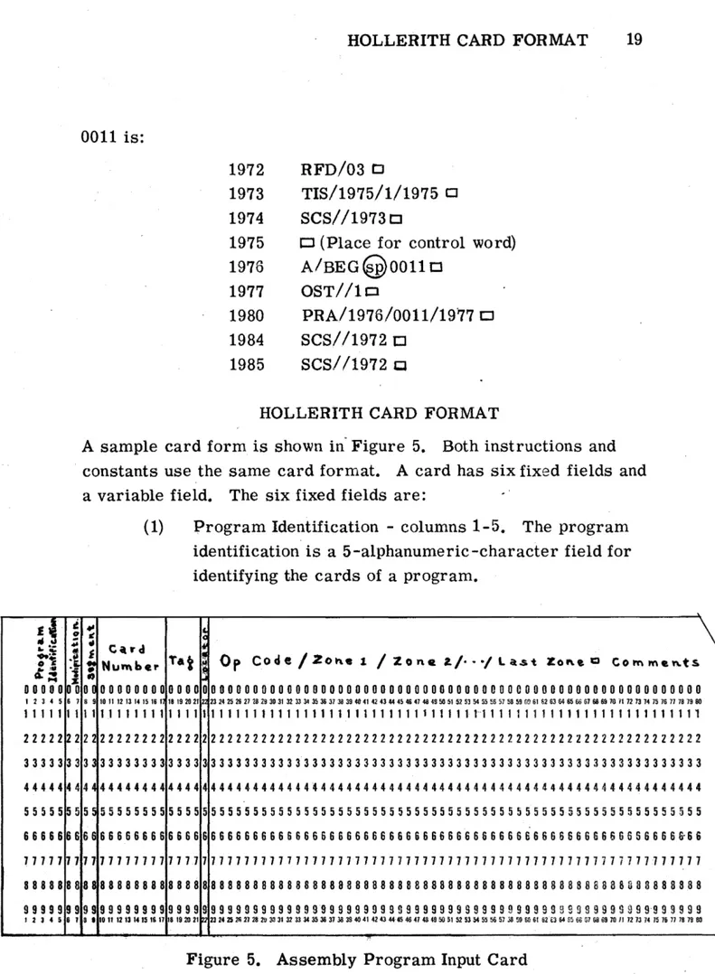
/1972 CJHOLLERITH CARD FORMAT
A sample card form is shown in" Figure 5. Both instructions and constants use the same card forrrlat. A card has six fixed fields and
a variable field. The six fixed fields are: .'
...
"
•
~,
"
008 9
1 1 22 33 44 55 66 77 88 99
3 •
(1) Program Identification - columns 1-5. The program
identification is a 5-alphanumeric-character field for identifying the cards of a program.
~
C'lrd
Tat , 0 p Cod e / Z 0 h.. 1 / Z 0 n fl l. / ••• / l a.s t Z 0 ~ e Q C 0 1"1'\ rn e '" ts
Nu",b.r
..
00000000 0000 00000000000000000000000000000000000000000000000000000000000
10 11 12 13 14 15 16 1 18 1920 21 2 n~~~vu~~,~~~~~~~~~o~~«~~~~~~~~n~~~~~~oo~~~~~~u~~ronnnH~~nn~oo
11111111 1 1 1 1 1 1 1 1 1 1 1 1 1 1 1 1 1 1 1 1 1 1 1 1 1 1 1 1 1 1 1 1 1 1 1 1 1'1 1 1 1 1 1 1 1 1 1 1 1 1 1 1 1 1 1 1 1 1 1 1 1 1 1 22222222 2222 22222222222222222222222222222222222222222222222222222222222 33333333 3 333 33333333333333333333333333333333333333333333333333333333333
44444444 4444 4444444444444~444444444444444444444444444444444444444444444
55555555 5 5 55 55555555555555555555555555555555555555555555555555555555555 66666666 6666 66666666666666 S 6 6 66666666666666666666666666 S 6 6 6 6 6 6 S 5 6 6 6 6 £-66 77711111 1177 1 7 7 1 7 11 7 11 7 1 7 7 11 7 711 7 11 7 7 1111 7 11 7 11 7 7 1 7 1 7 7 7 7 1 7 1 7 7 7 7 7 71 7 11 7 7
88888888 8 888 8 8 8 8 8 8 8 8 8 8 8 8 8 8 8 8 a 8 8 8 8 8 8 8 8 8 88 8 8 8 8 8 8 8 8 8 8 8 8 8 8 8 8 8 8 B 8 8 8 3 8 3 8 8 8 8 8 8 99999999 9999 9 999 9 9 9 9 9 9 9 9 9 99 9 9 9 9 9 9 9 9 S 9 9 999 9 9 S 9 9 9 9 9 9 9 9 9 9 9 9 9 9 9 9 9 9 99 9'9 9 9 9 9 9
10 11 12 13 14 15 III 17 18 192021 uu~~mn~~~~~~U~~~~~~~~~«~~~~~~~~~M~$~~~M~~D~e~~~~wnnnN~~n~~oo
20 HOLLERITH CARD FORMAT
(2) Modification Code - columns 6 - 7. The modification num-ber on all cards of a program is set initially. Every time
a program is modified by adding a set of correction cards at the end or by replacing a card, the modification num-ber on these cards is changed. Any alphanumeric charac-ters may be used for the purpose.
(3) Segment Identification - columns 8-9. The segment identi-fication consists of two decimal digits.
(4) Card Number - columns 10-17. The card number js a serial number identifying each card. Columns 10-14 are used for consecutive numbering and columns 15-17 contain fractional numbering which permits the insertion of words into the program after all of the cards have been prepared. As an example, if an insertion of two cards is put between cards numbered 15,427 and 15,428, the four cards might have the following numbers in columns 10-17.
Column 10 11 12 13 14 15 16 17
First Card 1 5 4 2 7 0 0 0
Insert A 1 5 4 2 7 1 0 0
Insert B 1 5 4 2 7 2 0 0
Second Card 1 5 4 2 8 0 0 .0
A further insertion at this point will result in
Column 10 11 12 13 14 15 16 17
First Card 1 5 4 2 7 0 0 0
Insert A 1 5 4 2 7 1 0 0
Insert A' 1 5 4 2 7 1 1 0
Insert B 1 5 4 2 7 2 0 0
Second Card 1 5 4 2 8 0 0 0
INPUT CONVERTER OPERATION 21
(5) Identification Tag - columns 18-21. The identification tag is the absolute or relative address of the instruction or con-stant on the card. If consecutive cards contain words for consecutive locations, loading time for the assembled pro-gram is shortened considerably.
(6) Locator - column 22. The locator column, L, contains an S if the instruction on the card is to be a sentinel. Otherwise, nothing appears in this column.
Starting at column 23, the instruction or constant is written, punctuated by slashes, and ended by a square. Comments may follow. Cards which contain only comments have a card number but no tag, and a square
appears in column 23. These cards are not processed, nor are any comments written on tape.
INPUT CONVERTER OPERATION
The program cards of several different programs to be assembled may be fed into the Input Converter as one large deck. The program identification in card columns 1 - 5 is used to distinguish among programs on the magnetic tape produced by the Input Converter. Care must be taken to insure that the same program identification appears on every card of a program and that each program assem-bled contains a unique program identification.
A special deck of five cards is used to indicate the end of the last program to be assembled on the Input Converter tape. These five cards must have the alphanumeric characters E 0 F R I in
columns 1 - 5. The information punched on the rest of the card is imma ·rial. These cards always follow the last card of the la§t
22 INPUT CONVERTER OPERATION
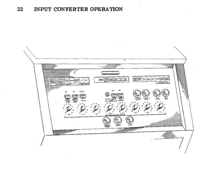
J
Figure 7 •. Input Converter Console
The Word 16 Check switch is set to stop for a converter error. The Eject switch is set to eject a card with an error. If a converter error occurs, the deck of cards in the input hopper of the Input Con-verter is moved back and the card with the conCon-verter error and those ejected with it are placed in front of the deck to be processed. Then the Converter Start button is pressed and processing continues.