A SYMMETRIC KEY BASED STEGANOGRAPHY
CALCULATION FOR ANCHORED INFORMATION
YAHIA SABRI AL-HALABI1
1Professor, Princess Sumaya University for Technology, Computer Science Department, Jordan E-mail: 1 [email protected]
ABSTRACT
Advancement in technology have brought about several sophisticated devices, using electronic media communication is more prone to attacks than communicating over traditional channels. While the traditional communication systems were insecure, it was rather more difficult to intercept communication without the communicating parties without the realization of the owner of the information being sent, due to either breaking of the seal to find out the content, or harm to the courier carrier. The message is open to all, once inserted into the shared network, or sent to the receiver from the sender, and moreover completely insecure. The message being sent must also conform to network security convention confidentiality, integrity, authentication and availability. In this paper, we followed some objectives in which we hid the message or a secret data into an image which acts as cover medium using LSB technique and how information exchange can be carried out using symmetric key based steganography. Steganography (LSB substitution) and two techniques of JPEG steganography (Jsteg and Steghide) taking secret information as a data file and as an image and to do comparisons between them in terms of embedding capacity and quality of produced stego-image and robustness to attacks. Also, video files are files that store motion pictures and sounds like in real life. In today's world, the need for automated processing of information in video file is increasing. Automated processing of information has a wide range of application including office/home surveillance cameras, traffic control, sports applications, remote object detection, and others. In particular, detection and tracking of object movement in video file plays an important role. This paper describes the methods of detecting objects in video files. Today, this problem in the field of computer vision is being studied worldwide.
Keywords: Information, Security of Secret Data, Key Based Steganography, Encryption.
1. INTRODUCTION
The rapid increase in the use of internet for communication has increased the threat to attacks to its users [1-3]. Information hiding is an emerging research area, which encompasses applications such as watermarking [4-6], cryptography [7-9], fingerprinting, steganography [10-12], and copyright protection for digital media. The best way of hiding secret message in media (carriers) such as image, audio, video, text, and protocol is Steganography [13].
Steganography is the art of concealing one digital media within another digital media and retrieving the information afterwards, while leaving no traces [14]. Steganography usage varies in method like: image into image, video into voice, text into image, voice into video, etc.
The word 'security' refers to the measures taken to ensure safety. But in spite of using many of the security procedures available there is no 100 percent security. In the past, only things with physical presence needed any form of protection and security (physical security).
Nowadays, information security is a vital aspect of security and it has become ultimately necessary to protect data and information with the best of techniques and approaches while also preventing them from being tampered. This protection is given during transmission of data or when the data is saved in the appropriate media device.
1.1 Steganography Techniques
The majority of today’s steganographic systems utilizes multimedia objects like image, audio, & video etc. as cover media because people often transmit digital pictures over email and other Internet communication. Modern steganography approaches hide information into digital files using the cover medium (C) that will hold message, secret message(M), may be plain text, digital image file or any type of data, and a stego key which may be used to hide and unhide the message [14].
2. RELATED WORK
Secure data transmission over internet is achieved using Steganography with High Capacity and Security Steganography using discrete wavelet transforms (HCSSD). The capacity of the proposed algorithm is increased as the only approximation band of payload was considered [15]. Major importance is given on the secrecy as well as the privacy of information as Image Steganography [16].
Embedded of embedding process is hidden under the transformation (DWT and IDWT) of cover image. These operations provide sufficient secrecy. Steganography technique by modifying an audio signals. They have developed their using genetic algorithm, message bits could be embedded into multiple, vague and deeper layers to achieve higher capacity and robustness [17]. A novel steganographic approach called tri-way pixel-value differencing (TPVD) is used for embedding. All the processes are defined and executed in the compressed domain [18].
Embedding the text file in a video file in such a way that the video does not lose its functionality using DCT & LSB Modification method. This method applied imperceptible modification. This Stego system implements steganography in video image and reveal process without restarting a different application [19].
Also this system is Platform Independent application with high portability and high consistency. Hash based LSB technique for video steganography. The Proposed Method is analyzed in term of both Peak Signal to Noise Ratio (PSNR) compared to the original cover video as well as the Mean Square Error (MSE) measured between the original and steganographic files averaged over all video
frames. This is done with help of edge detection filters [20].
By using the edge detection approach along with least significant bit method leads to high security even with a little object as an image, the embedded image is just like the original one. A data hiding scheme was being developed to hide the information in specific frames of the video and in specific location of the frame by LSB substitution using polynomial equation [21].
This information was embedded based on the stego key. A framework for hiding large volumes of data in images by combining cryptography and steganography while incurring minimal perceptual degradation and to solve the problem of unauthorized data access [22]. Steganography over Video File using Random Byte Hiding and LSB Technique [23].
2.1 Organization of Paper
The remaining parts of this paper is organized into five sections;
Section 2: The Spatial Domain techniques of steganography are explained. The two techniques, LSB substitution and distortion, are explained with algorithm.
Section 3: Proposed Algorithm; first of all, the JPEG compression which is the necessary step of JPEG steganography, is explained. Then various techniques of JPEG steganography are described. Two techniques which are implemented in paper (Jsteg and Steg-Hide) are explained with algorithms.
Section 4: describes the method and algorithm of objects in video files.
Section 5: simulation parameters and results of these four techniques are analyzed.
Section 6: includes the concluding remarks and the future scope of the project. In the end, references of research paper.
3. PROPOSED MODEL AND KEY
GENERATION
Both the keys are sent to receiver using a shared secure communication channel. In the first part we discuss the AES Encryption and Decryption for message encryption and decryption and Random LSB Insertion and Embedding Technique for data hiding. We then discuss the operations at sending and receiving part with block diagram below in detail.
3.1 AES Encryption
It is based on the block cipher Rijndael and works in a substitution-permutation network [24]. AES has a fixed block size of 128 bits and a key size of 128, 192, or 256 bits. It has 10 rounds for 128-bit keys, 12 rounds for 192-bit keys, and 14 rounds for 256-bit keys. It operates on a 4×4 column-major order matrix of bytes, termed the state .The AES cipher is specified as a number of repetitions of transformation rounds that convert the input plaintext into the final output of ciphertext. The proposed model employs 256 bit keys for message encryption. The algorithm for message encryption consists of following steps:
Step1. Generate the substitution tables.
Step2. Define the round constant vector and correct key.
Step3. Compute the expanded key schedule. Step4 Create a polynomial matrix.
Step5. To generate AES cipher for plaintext, 14 round transformations is performed where each round consist of four steps viz. Substituting bytes, Shifting rows, Mixing columns, and Adding round key.
During decryption, each round comprises of four steps:
Step1. Inverting shift rows.
Step2. Inverting the substituted bytes. Step3. Adding the round keys. Step4. Inversing the mixed columns.
In the 3rd step, resultant of step 1 and step 2 are XORed with four words from the key schedule [24].
3.2 Random LSB Insertion Technique using Discrete Logarithm
If I is the cover image, m is the encrypted message and k is the stego key, the stego-image I’ is mathematically defined by Equation (1)
I' f (I,m,k) (1)
The simple LSB insertion technique hides the message using sequence-mapping technique in the pixels of a cover-image which allows steganalyst to retrieve the message due to simplicity of the algorithm. To tackle this menace, the encrypted data is hidden in pixels of the cover-image generated using discrete logarithm calculation. Discrete logarithm generates random numbers without any repetition. With this set of random numbers, a random-mapping can be done. Mathematically we define discrete logarithm as follows:
If a is a primitive root of the prime number p, then the numbers a mod p, a2 mod p, …, a p-1mod p are distinct and consist of the integers from 1 through (p – 1) in some permutation.
Therefore, if a is the primitive root of p, then its
p-1
powers a, a2, ………….a are all relatively prime to p with distinct numbers. For any integer y and a primitive root a of prime number p, a unique exponent i is determined so that y ・ai mod p (2) where 0 ≤ i ≤ (p - 1).
The exponent i is referred the discrete logarithm. The key steps of random LSB insertion technique are as follows:
Step1. Select the cover image to embed the secret message.
Step2. Select a key such that its value lies between size of message m and Image I. Step3. Determine a prime number p, by searching for the 1st prime number greater than key, k.
Step4. Then a primitive root, a, is derived as per equation (2).
Step5. The primitive root, a, is then used to generate a set of random numbers yi. This set of random numbers determines the position of pixel where the message bits are embedded. The discrete logarithm ensures that distinct pixel is chosen.
Step6. The message bits are inserted in the cover-image using the relation defined in equation 3:
Mi ・Iyi (3)
where Mi is the ith bit of the message, and Iyi is
the ith random number generated. Extracting hidden message from stego image
is then used for selecting the positions of the pixel where the secret bits are hidden. For data extraction, the above algorithm is employed in reverse order.
3.3 Sending and Receiving
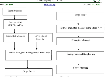
During the sending stage, the secret data is sent through an insecure communication channel. The key tasks include encryption of secret message using AES algorithm and steganographic embedding using Random LSB insertion technique. Figure 1a represents the operations at sender’s end. After the receipt of Stego image, the recipient first, extracts out of the encrypted message with the help of Stego Key and then decrypts it with the cipher key. Figure 1b represents the operations at recipient’s end.
[Figure 1 near here]
4. SECTION 2
4.1 LSB Substitution:
In this type, the data to be hidden is inserted into the least significant bits of the pixel
information [20]. Increase or decrease of value by changing the least significant bit, do not change the appearance of the image, such that the resulted stego-image looks exactly same as the cover image.
A more refined approach is the use of a pseudorandom number generator to spread the secret message over the cover in a rather random manner [25]. A popular approach is the random interval method. If both communicators share a stego-key k usable as a seed for a random number generator, they can create a random sequence k1,….., kl(m) and use the elements with indices
J1 = k1
Ji = ji-1 + ki, i ≥2
for information transfer. Thus, the distance between two embedded bits is determined pseudo randomly. Since the receiver has access to the seed k and knowledge of the pseudorandom number generator, he can reconstruct ki and therefore the entire sequence of element indices ji.
These classic LSB steganography have a common weak point [26]. The sample value
changes asymmetrically When the LSB of cover medium sample value is equal to the message bit, no change should be made. Otherwise, change the value 2n to 2n+1 or 2n+1 to 2n. But the changes from 2n to 2n-1 or from 2n+1 to 2n+2 will never emerge. This dissymmetry is utilized by steganalysis such as Chi-square analysis and RS pair analysis.
In this paper, LSB with psuedo random generator is implemented. Matlab inbuilt pseudo-random number generator is used for this purpose and seed to this is taken as key of steganography. Then with the help of this array, different pixel positions are calculated. Now secret bits are embedded to LSB of these quality pixels.
4.1.1 Embedding algorithm:
Input: cover image, key, secret message Procedure:
Step1: Convert the secret message into bit stream (Length L)
Step2: Generate L number of pseudo random number using seed key
Step3: Calculate the non-collide L pixel positions in the cover image
Step4: while complete bit stream not embedded [Replace LSB of pixel denoted by ith pixel position, with secret bit; Insert pixel into cover image]
End
Output: Stego-image
On the receiver side, first of all the pixel positions are calculated in the same way with the use of the same key. Then secret bit-stream is formed by the LSBs of these pixels. The Extraction algorithm is as below:
4.1.2 Extraction algorithm: Input: stego-image, key Procedure:
Step1: Convert the secret message into bit stream (Length L)
Step2: Generate L number of pseudo random number using seed key
Step3: Calculate the non-collide L pixel positions in the cover image
Step4: for i=1 to L
{Get lsb of pixel denoted by ith pixel position} {Append this lsb into secret bit stream} Step5: Convert secret bit stream into secret message
End
Advantages:
•
There is less chance for degradation of the original image.•
More information can be stored in an image i.e. hiding capacity is more. Disadvantages:•
Less robust, the hidden data can be lost with image manipulation.•
Hidden data can be easily detected by simple attacks.4.2 Distortion:
Distortion techniques require the knowledge of the original cover in the decoding process [20]. We apply a sequence of modifications to a cover in order to get a stego-image in such a way that it corresponds to a specific secret message for embedding. Receiver measures the differences to the original cover in order to reconstruct the sequence of modifications applied by sender, which corresponds to the secret message.
Using a similar approach as in LSB, the sender first chooses l(m) different cover-pixels he wants to use for information transfer. Such a selection can again be done using pseudorandom number generators or pseudorandom permutations. To encode a 0 in one pixel, the sender leaves the pixel unchanged; to encode a 1, he adds a random value x to the pixel's color. Although this approach is similar to a substitution system, there is one significant difference: the LSB of the selected color values do not necessarily equal secret message bits. In particular, no cover modifications are needed when coding a 0. Furthermore, x can be chosen in a way that better preserves the cover's statistical properties.
The receiver compares all l(m) selected pixels of the stego-object with the corresponding pixels of the original cover. If the ith pixel differs, the ith message bit is a 1, otherwise a 0.
In this project the value of x is taken as 1 so that minimum deflection from cover image will produced. We defined a middle level of pixel value, such that if the pixel value is greater than this value than x is added to pixel value otherwise x is subtracted from the pixel value. In this way the high PSNR will produce and no problem of overflow will occur.
The embedding algorithm for this technique is as below:
4.2.1 Embedding algorithm:
Input: cover image, key, secret message Procedure:
Step1: Convert the secret message into bit stream (Length L)
Step2: Generate L number of pseudo random number using seed key
Step3: Calculate the non-collide L pixel positions in the cover image
Step4: while complete bit stream not embedded
{If secret bit=1} {If pixel value < 128} {Increase pixel value by x}
Else
{Decrease pixel value by x} End
Output: Stego-image
On the receiver side, first of all the difference between the pixel values of cover image and stegoimage is calculated. Then pixel positions are calculated in the same way with the use of the key and pseudo random number generator. If the difference at a location is 0 then secret bit is taken as 0 otherwise it is taken as 1. The algorithm for extraction process is as below:
4.2.2 Extraction algorithm:
Input: cover image, key, stego-image Procedure:
Step1: Convert the secret message into bit stream (Length L)
Step2: Generate L number of pseudo random number using seed key
Step3: Calculate the non-collide L pixel positions in the cover image
Step4: Calculate the difference between Cover image and Stego-image
Step5: for i=1 to L
{If value of pixel difference=0}
{Secret bit =0}
Else
{Secret bit=1} Step 6: Convert the bit stream into secret message
End
Output: secret message
Advantages:
•
Embedding capacity is highest, simple and less complicated.Disadvantages:
•
In many applications, this technique is not useful, since the receiver must have access to the original covers.5. SECTION 3
5.1 Determination of Location of Message; Proposed Algorithm:
In the paper, JPEG steganography [27] is implemented which use Discrete Cosine Transform [28] to convert image into frequency domain. Before discussing these techniques in detail we first discuss the JPEG compression because JPEG steganography is just the modified version of JPEG compression.
5.2 JPEG Compression
The fact that, consumer-level computers had enough processing power to manipulate and display full color photographs. However, full color photographs required a tremendous amount of bandwidth when transferred over a network connection, and required just as much space to store a local copy of the image. Other compression techniques had major tradeoffs.
JPEG compression and decompression consist of 4 distinct and independent phases. First, the image is divided into 8 x 8 pixel blocks. Next, a discrete cosine transform is applied to each block to convert the information from the spatial domain to the frequency domain. After that, the frequency information is quantized to remove unnecessary information. Finally, standard compression techniques compress the final bit stream. The basic flow of JPEG is as follows:
[Figure 2 near here]
5.2.1 Phase one: Divide the image
Attempting to compress an entire image would not yield optimal results. Therefore, JPEG divides the image into matrices of 8 x 8 pixel blocks. If the image dimensions are not multiples of 8, extra pixels are added to the bottom and right part of the image to pad it to the next multiple of 8 so that we create only full blocks.
It may include a change in color space. Normally, JPEG will convert RGB color space to YCbCr color space. In YCbCr, Y is the luminance, which represents the intensity of the color. Cb and Cr are chrominance values, and they actually describe the color itself. YCbCr tends to compress more tightly than RGB.
5.2.2 Phase two: Conversion to the frequency domain
In JPEG all 8 x 8 blocks are converted to frequency domain using DCT. The Discrete
Cosine Transform (DCT) is derived from the FFT, however it requires fewer multiplications than the FFT since it works only with real numbers. Also, the DCT produces fewer significant coefficients in its result, which leads to greater compression.
The frequency domain matrix contains values from -1024…1023. The upper-left entry, also known as the DC value, is the average of the entire block, and is the lowest frequency cosine coefficient. As we move right the coefficients represent cosine functions in the vertical direction that increase in frequency. Likewise, as we move down, the coefficients belong to increasing frequency cosine functions in the horizontal direction. The highest frequency values occur at the lower-right part of the matrix. The higher frequency values also have a natural tendency to be significantly smaller than the low frequency coefficients since they contribute much less to the image. This essentially removes half of the data per block, which is one reason why JPEG is so efficient at compression. Computing the DCT is the most time-consuming part of JPEG compression. Thus, it determines the worst-case running time of the algorithm.
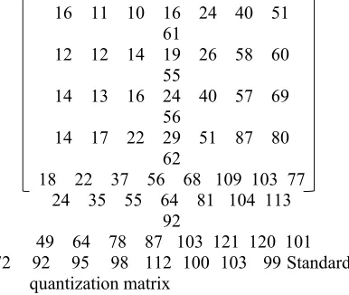
5.2.3 Phase three: Quantization
decompression routine will know the values that were used to divide each coefficient. The constant values that are used in the division may be arbitrary, although research has determined some very good typical values. The standard quantization matrix used in JPEG is as below:
16 11 10 16 24 40 51 61
12 12 14 19 26 58 60 55
14 13 16 24 40 57 69 56
14 17 22 29 51 87 80 62
18 22 37 56 68 109 103 77 24 35 55 64 81 104 113
92
49 64 78 87 103 121 120 101 72 92 95 98 112 100 103 99 Standard
quantization matrix
Dividing by a high constant value can introduce more error in the rounding process, but high constant values have another effect. This is especially true for the high frequency coefficients, since they tend to be the smallest values in the matrix. Thus, many of the frequency values become zero.
The algorithm used to calculate the quantized frequency matrix is fairly simple. It takes a value from the frequency matrix (F) and divides it by its corresponding value in the quantization matrix (Q). This gives the final value for the location in the quantized frequency matrix (Fquantize). The quantization equation that is used for each block in the image is below:
FQuantize (u,v)={ ,, + 0.5
By adding 0.5 to each value, we essentially round it off automatically when we truncate it, without performing any comparisons.
5.2.4 Phase four: Entropy coding:
After quantization, the algorithm is left with blocks of 64 values, many of which are zero. Of course, the best way to compress this type of data would be to collect all the zero values together, which is exactly what JPEG does. The algorithm uses a zigzag ordered encoding, which collects the high frequency quantized values into long strings of zeros.
[image:7.612.94.287.173.336.2]To perform a zigzag encoding on a block, the algorithm starts at the DC value and begins winding its way down the matrix, as shown in figure. This converts an 8 x 8 table into a 1 x 64 vector.
5.3 JPEG Steganography
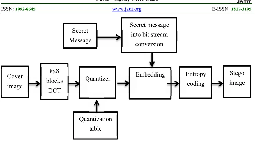
JPEG steganography is more important and popular because stago-image produce by these techniques are robust to jpeg compression. In this technique secret data is embed after quantization phase of JPEG compression. Only significant quantized DCT coefficients are modified according to secret bits. Remaining steps are similar to JPEG compression. In this way stego-image is produced in .jpg format directly. The basic flow diagram of embedding and extraction process is as below:
[Figure 3 near here]
[Figure 4 near here]
Following are some JPEG steganography techniques:
•
Jsteg•
Steghide•
Outguess•
F3,F4,F5•
J3In the paper, only 2 techniques Jsteg and Steghide is implemented and these are explained below with algorithms.
5.3.1 Jpeg-Jsteg:
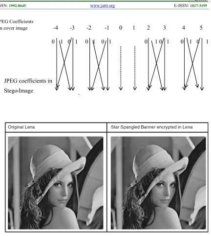
In Jpeg–Jsteg, the secret messages are embedded in LSB of quantized DCT coefficients whose values are not (0, 1, or 1). Its execution steps are described briefly as follows. First, JPEG partitions a cover-image into non-overlapping blocks of 8*8 pixels, and then it uses DCT to transform each block into DCT coefficients. The results of the DCT coefficients are scaled according to a quantization table.
0, 1, or 1. The bit-flip diagram of J-steg is as below:
[Figure 5 near here]
The embedding sequence employed in Jpeg– Jsteg is in the zigzag scan order, which is listed in fig. After embedding the secret message in each block, Jpeg–Jsteg uses Huffman coding, Run-Length coding, and DPCM of JPEG entropy coding to compress each block. Finally, Jpeg– Jsteg obtains a JPEG stego-image.
The message capacity of Jpeg–Jsteg is limited. If there are many quantifized coefficients equal to 0, 1, or 1, then the message capacity of Jpeg–Jsteg will be decreased. Besides, in DCT transformation, most important coefficients are located around the low-frequency part. Jpeg– Jsteg modifies the quantized DCT coefficients right in the low-frequency part. Therefore, the image quality of Jpeg–Jsteg is degraded, especially when the cover-image undergoes a high compression ratio.
5.3.2 Embedding algorithm:
Input: secret message, cover image Procedure: Step1. Convert the secret message into bit stream Step2. Divide the cover image into 8x8blocks Step3. Calculate DCT coefficients for each block Step4. Quantize the coefficients
Step5. While complete message not embedded do
[Get next DCT coefficient
If DCT ≠ 0, DCT ≠1 and DCT ≠ -1 then {Get next bit from message
replace DCT LSB with message bit}] Step6. De-quantize and take inverse DCT to obtain stego-image End.
Output: Stego- image
5.3.3 Extracting algorithm: Input: Stego image Procedure:
Step1. Divide the stego image into 8x8 blocks Step2. Calculate DCT coefficients for each block Step3. Quantize the coefficients
Step4. While secret message not completed do [Get next DCT coefficient
If DCT ≠ 0, DCT ≠1and DCT ≠ -1 then {Concatenate DCT LSB to secret message bit steam}]
Step5. Convert secret message bit stream into the message.
End.
Output: Secret message
Advantages:
•
Robust to JPEG compression.•
Less bandwidth requirement for stego image transmissionDisadvantages:
•
Only few secret messages can be embedded in cover image.•
High detectability.5.4 Steg-Hide:
Steghide uses a graph-theoretic approach to steganography. Steghide embeds by swapping DCT coefficients and thus avoids changing the histogram. The fact that the embedding is done by exchanging pixel values implies that the first-order statistics (i.e. the number of times a color occurs in the picture) is not changed. During the encoding process, the sender splits the coverimage in 8 x 8 pixel blocks; each block encodes exactly one secret message bit. The embedding process starts with selecting a pseudorandom block bi which will be used to code the ith message bit [31].
Before the communication starts, both sender and receiver have to agree on the location of two DCT coefficients, which will be used in the embedding process; let us denote these two indices by (u1,v1) and (u2, v2). The two coefficients should correspond to cosine functions with middle frequencies; this ensures that the information is stored in significant parts of the signal (hence the embedded information will not be completely damaged by JPEG compression) [31].
5.4.1 Embedding algorithm:
Input: secret message, cover image Procedure: Step1. Convert the secret message into bit stream Step2. Divide the cover image into 8x8blocks Step3. Calculate DCT coefficients for each block Step4. Quantize the coefficients
Step5. While complete message not embedded do
[Get next block
If block (u1, v1) ≠ block (u2, v2) then {Get next bit from message stream
If bit =1 and block (u1, v1) < block (u2, v2) {Swap (block (u1, v1), block (u2, v2)} If bit =0 and block (u1, v1)> block (u2, v2) {Swap (block (u1, v1), block (u2, v2)}}]
Output: Stego- image
5.4.2 Extracting algorithm: Input: Stego image Procedure:
Step1. Divide the stego image into 8x8 blocks Step2. Calculate DCT coefficients for each block Step3. Quantize the coefficients
Step4. While secret message not completed do [Get next block
If block (u1, v1) ≠ block (u2, v2) then {If block (u1, v1) < block (u2, v2)
{Concatenate 0 to bit stream Else
Concatenate 0 to bit stream}}] Step5. Convert secret message bit stream into the message. End.
Output: Secret message
Advantage:
•
It cannot be detected by steganalysis which uses first order characteristics, provides robustness to jsteg.Disadvantage:
•
Its embedding capacity is less than Jsteg too.6. SECTION 4
6.1 Methods And Algorithm Of Objects In Moving Video
As we all know, video is a collection of discrete images that are constantly displayed to create motion effects. Thus, object detection in video files is also based on the idea of detecting objects in an image file [35]. We need to perform the image-partitioning step to determine where the area of objects is, and where the area of the background is. An image is a detail, an object in panorama. An image area describes the surface properties of an image; this area is surrounded by a boundary and points with a relatively uniform grey level. Based on the physical properties of the image area, we define a number of partitioning techniques. The main partitioning methods include:
- Classification or threshold-based method.
- Structure-based method. - Boundary-based method
Traction is a part of motion-moving technology in static scenes. It tries to detect motion regions by subtracting pixels from the
current image to a background image that was created by the average background image for a period of one initialization cycle. There are several approaches, which can be presented as follows.
Let In(x, y) be a representation of the greyscale intensity value at a pixel location (x, y) with a value of [0 ÷ 255] in the nth case of the video sequence I. Let Bn(x) be a corresponding background magnitude) value for a pixel at time (x, y) estimated from the video image I0 to In1. A pixel in position (x, y) in the current image belongs to the dominant component highlighted if
| It (x, y) – Bt (x, y) | > Tn (x, y) (1)
is satisfied, where Tn (x, y) is a predefined threshold.
The Bt background image is updated by using the Infinite Impulse Respone (IIR) filter as follows:
Bt+1 = α.It + (1- α).Bt This background is updated for all types of
pixels. In the background subtraction methods, the source background image is updated only for pixels in the background.
6.2 Static Methods
The W4 method uses a static background pattern, where each pixel is represented again with the smallest value (M) and its maximum value (N) in terms of intensity and maximum intensity difference (D) between any consecutive frames observed during the training initialization cycle, in which the scene does not contain moving objects. One point in the current image is classified as a prominent feature if it satisfies:
| M(x, y) - It(x, y) | > D(x, y) or | N(x, y) - It(x, y) | > D(x, y) (3
Every pixel is modelled by a blend of the Gaussian methods and is updated online by the input image data. Gaussian distributions will evaluate whether a point belongs to the dominant point processing or to the underlying processing.
[Figure 6 near here]
Detecting and tracking objects in video files encounters the following issues: Brightness change; the brightness of an image can change in space and time; some parts of an object may be brighter and brightness of objects in the current image may become darker on the next day [36]. Ability to expand or shrink an object. An object can move close to or move out of the camera's frame. The natural work can be attributed to the incorrect operation of the photo (video) camera and all the natural conditions such as snowfall or rain, under which the image (video) is obtained. Artificially created reasons include all human actions aimed to change the image quality such as changing color space, compression of the image with loss of quality, blurring of the image, and others. Change of the geometric shape of an object. The observed object can be deformed because it can turn to the camera with a part, which differs from the form observed before.
6.4 Methods for Searching Objects
The main methods and algorithms for searching objects include the following:
Dense optical flow. These algorithms help to estimate the motion vector of every pixel in a video frame.
Sparse optical flow. These algorithms, like the Kanade-Lucas-Tomashi (KLT) feature tracker, track the location of a few feature points in an image.
Kalman Filtering. This is a very popular signal-processing algorithm used to predict location of a moving object based on prior motion information. One of the early applications of this algorithm was missile guidance! Moreover, the on-board computer that guided the descent of the Apollo 11 lunar module to the moon had a Kalman filter
Mean shift and Cam shift. These are algorithms for locating the maxima of a density function. They are also used for tracking.
Single object trackers. In this class of trackers, the first frame is marked using a rectangle to indicate location of the object we want to track. The object is then tracked in subsequent frames using the tracking algorithm. In most real life
applications, these trackers are used in conjunction with an object detector.
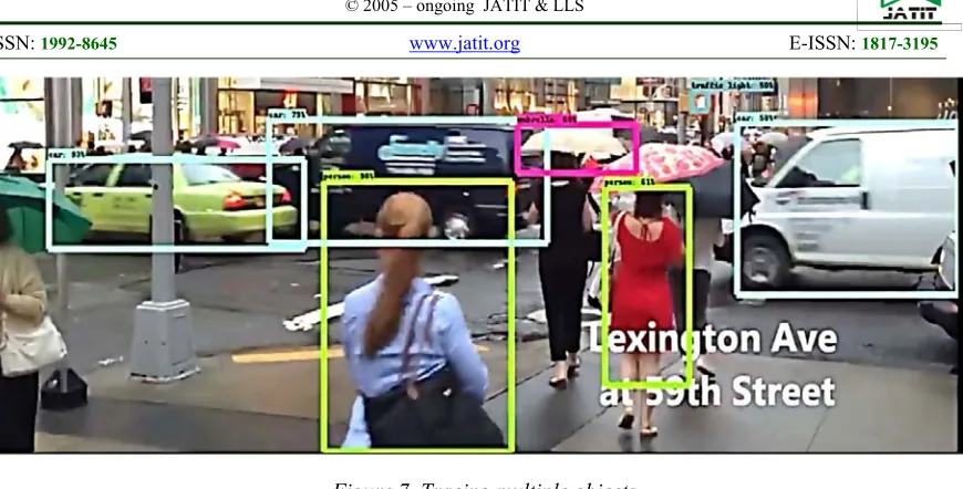
Multiple object track finding algorithms. In cases, when we have a fast object detector, it makes sense to detect multiple objects in each frame and then run a track finding algorithm that identifies, which rectangle in one frame corresponds to a rectangle in the next frame. Such algorithm is shown in Figure 3.
[Figure 7 near here]
7. SECTION 5
7.1 Experimental Results from New Technique
7.1.1 Simulation setup:
The MATLAB Version 7.13.0.564 (R2011b) is used to implement and simulate 4 steganography techniques: LSB & Distortion of spatial domain steganography and Jsteg & Steg-hide of transform domain steganography. MATLAB is used because of large number of advanced inbuilt functions and image processing toolbox. We take results for various color cover image for different secret files.
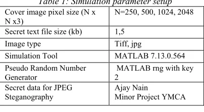
[image:10.612.319.521.493.604.2]The various simulation parameters are as given below:
Table 1: Simulation parameter setup Cover image pixel size (N x
N x3)
N=250, 500, 1024, 2048
Secret text file size (kb) 1,5 Image type Tiff, jpg
Simulation Tool MATLAB 7.13.0.564 Pseudo Random Number
Generator
MATLAB rng with key 2
Secret data for JPEG Steganography
Ajay Nain
Minor Project YMCA
The following results are taken for evaluation of these techniques:
7.1.2 Perceptual quality:
[Figure 8 near here]
We see that there is no so much change in perceptual quality of image to detect visual changes i.e. quality of embedded image is not degraded by these techniques.
[Figure 9 near here]
Result shows that visual quality of stego-image produced by spatial domain techniques is less than that of produced by transform domain techniques. In spatial domain techniques as the size of secret file changes the more degradation is produced but in case of the degradation of image depends not upon size of secret file so much.
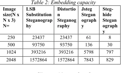
7.2 Embedding Capacity
It is the size of the secret data that can be embed in cover image without deteriorating the integrity of the cover image. It can be represented in bytes. It depends upon the characteristics of cover image and the embedding algorithm used for steganography [37].
[image:11.612.319.522.266.400.2]The table shows the embedding capacity of the 4 techniques for different cover image:
Table 2: Embedding capacity Image
size(N x N x 3) N= LSB Substitution Steganograp hy Distortio n Steganog raphy Jsteg Stegan ograph y Steg-hide Stegan ograph y 250 23437 23437 61 8 500 93750 93750 136 30 1024 393216 393216 5798 797 2048 1572864 1572864 7843 829
[Figure 10 near here]
Result shows that embedding capacity of spatial domain capacity is fix large quantity for a cover image size but capacity of transform domain techniques is very less and it is not fixed for a given size of cover image, it depends upon characteristics of cover image.
7.3 Mean Square Error (MSE):
It is defined as the square of error between cover image and stego-image. The distortion in the image can be measured using MSE and is calculated using Equation 1.
…… (1)
Where:
The intensity value of the pixel in the cover image.
: The intensity value of the pixel in the stego image.
M*N: Size of an Image.
[image:11.612.85.288.440.560.2]The results of the all techniques for the given setup parameters are in the following table:
Table 3: MSE
[Figure 11 near here]
The MSE for spatial domain techniques is very less than that of for transform domain technique. In case of transform domain techniques the lossy compression step of jpeg compression i.e. quantization is performed in the embedding process and hence very large MSE is produced and quality of cover image degraded more.
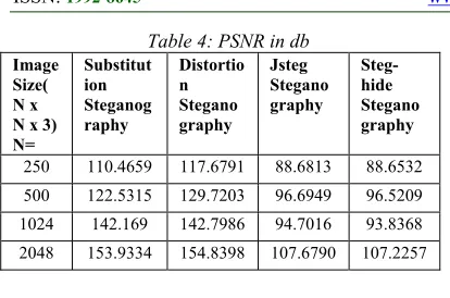
7.4 Peak Signal to Noise Ratio (PSNR)
It is defined as the ratio of peak square value of pixels by MSE [38]. It is expressed in decibel. It measures the statistical difference between the cover and stego-image, is calculated using Equation 2.
……. (2)
It is the measure of quality of the image by comparing the cover image with the stego-image. High PSNR indicates good perceptual quality of stego-image. The results of PSNR for all the techniques are in following table:
Image size(N x N x 3) N= LSB Substitut ion Steganog raphy Distortion Steganogr aphy Jsteg Steganogr aphy Steg-hide Steganogr aphy
Table 4: PSNR in db Image
Size( N x N x 3) N= Substitut ion Steganog raphy Distortio n Stegano graphy Jsteg Stegano graphy Steg-hide Stegano graphy
250 110.4659 117.6791 88.6813 88.6532 500 122.5315 129.7203 96.6949 96.5209 1024 142.169 142.7986 94.7016 93.8368 2048 153.9334 154.8398 107.6790 107.2257
[Figure 12 near here]
8. SECTION 6
8.1 Conclusion and Future Scope
8.1.1 Conclusion
Spatial domain techniques are easy ways to embed information, but they are highly vulnerable to even small cover modifications. Hence the size of stago-image cannot be reduced. Transform-domain methods hide messages in significant areas of the cover image which makes them more robust to attacks, such as compression, cropping, and some image processing. Hence lossy compression i.e. Jpeg compression can be done and size of stago-image can be reduced. The embedding capacity of Jpeg steganography is very less than spatial domain techniques. The spatial domain techniques provide high PSNR, high perceptual quality and high embedding capacity but these not provide robustness. On the other hand transform domain provide robustness while providing very less embedding capacity, low PSNR and low perceptual quality. In order to cope with the aforementioned issues, we propose an efficient method of steganography in which the message or secret data is embedded in the image which acts as cover medium. We accomplish this by using LSB technique and the exchange of information is performed using symmetric key based steganography. In addition, anti-jamming algorithms are not suitable for finding objects in the video files. On the contrary, the method proposed in this work is based on finding the main characteristics of the object. In comparison with other methods, the algorithm proposed in this work remains unaffected by projective transformations and is resistant to noise and brightness change. Moreover, the algorithm proposed in this work is computationally effective as compared to the other previous methods. On the basis of these qualities, this
method works better than spatial domain techniques of steganography resulting in a more secure and computationally efficient algorithm for steganography.
The further research is oriented for designing such an algorithm that is able to detect fast-moving objects in video files. The implications of which can be detecting potentially dangerous objects or a person. This algorithm can be used for detecting dangerous people who carry suspicious weapons or other things that must be checked.
8.1.2 Future scope
We see there is a tradeoff between the three properties, perceptuality, embedding capacity and robustness. The new techniques should be developed to maintain the three properties at high level. The few areas which are still open in steganography are as below:
•
Wavelet transform can be used to increase the embedding capacity while maintaining the robustness of Stego-image.•
Hamming coding or Matrix coding can be used to reduce the impact of steganography i.e. to increase the PSNR.REFERENCES:
[1] George Danezis, and Claudia Diaz, “A survey of anonymous communication channels”, Technical Report MSR-TR-2008-35, Microsoft Research, 2008.
[2] Vishnu Navda, Aniruddha Bohra, Samrat Ganguly, and Dan Rubenstein, “Using channel hopping to increase 802.11 resilience to jamming attacks”, In IEEE INFOCOM 2007-26th IEEE International Conference on Computer Communications, 2007, pp. 2526-2530.
[3] Katharina Krombholz, Heidelinde Hobel, Markus Huber, and Edhgar Weippl, “Advanced social engineering attacks”,
Journal of Information Security and applications, Vol. 22, 2015, pp. 113-22. [4] Christine Podilchuk, and Edward J. Delp,
“Digital watermarking: algorithms and applications”, IEEE signal processing Magazine, Vol. 18, No. 4, 2001, pp. 33-46. [5] Peter Meerwald, Andreas Uhl, “Survey of
wavelet-domain watermarking algorithms”,
Society for Optics and Photonics, Vol. 4314, 2001, pp. 505-516.
[6] Michael Arnold, “Audio watermarking: Features, applications and algorithms”, In 2000 IEEE International Conference on Multimedia and Expo. ICME2000. Proceedings. Latest Advances in the Fast-Changing World of Multimedia (Cat. No. 00TH8532), Vol. 2, 2000, pp. 1013-1016. [7] Mitali, Vijay Kumar, and Arvind Sharma, “A
survey on various cryptography techniques”,
International Journal of Emerging Trends & Technology in Computer Science (IJETTCS), Vol. 3, No. 4, 2014, pp. 307-12. [8] Murilo S. Baptista, “Cryptography with
chaos”, Physics letters A, Vol. 240, No. 1-2, 1998, pp. 50-54.
[9] Fahad A. Munir, Muhammad Zia, and Hasan Mahmood, “Designing multi-dimensional logistic map with fixed-point finite precision”, Nonlinear Dynamics, Vol. 97, No. 4, 2019, pp. 2147-58.
[10] Rajarathnam Chandramouli, Nasir Memon, “Analysis of LSB based image steganography techniques”, In Proceedings 2001 International Conference on Image Processing (Cat. No. 01CH37205), Vol. 3, 2001, pp. 1019-1022.
[11] Mehdi Hussain, “A survey of image steganography techniques”, International Journal of Advanced Science and Technology, Vol. 54, 2013.
[12] Nagham Hamid, Abid Yahya, R.Badlishah Ahmad, and Osama Al-Qershi, “Image steganography techniques: an overview”,
International Journal of Computer Science and Security (IJCSS), Vol. 6, No. 3, 2012, pp.168-87.
[13] VenkatramanS, Ajith Abraham, Marcin Paprzycki, “Significance of steganography on data security”, In International Conference on Information Technology: Coding and Computing, 2004. Proceedings. ITCC 2004, Vol. 2, 2004, pp. 347-351. [14] Neil F. Johnson, Sushil Jajodia, “Exploring
steganography: Seeing the unseen”,
Computer, Vol. 31, No. 2, 1998, pp. 26-34. [15] H S Manjunatha Reddy and Kumar
Bommana Raja, “High Capacity and Security Steganography Using Discrete Wavelet Transform”, International Journal of Computer Science and Security, Vol. 3, No. 6, 2010, pp. 462-472.
[16] Amitava Nag, Sushanta Biswas, Debasree Sarkar and Partha Pratim Sarkar, “A Novel
Technique for Image Steganography Based on DWT and Huffman Encoding”,
International Journal of Computer Science and Security, Vol. 4, No. 6, 2011, pp. 561-570.
[17] Mazdak Zamani, Rabiah Ahmad, Azizah Abdul Manaf and Farhang Jaryani, “A Secure Audio Steganography Approach”,
International Conference for Internet Technology and Secured Transactions (ICITST), IEEE Xplore, London, UK, 2009, DOI: 10.1109/ICITST.2009.5402644. [18] Sherly A P and Amritha P P, “A
Compressed Video Steganography Using TPVD”, International Journal of Database Management Systems (IJDMS), Vol. 2, No. 3, 2010, pp. 67-80.
[19] Poonam V Bodhak and Baisa L Gunjal, “Improved Protection in Video Steganography Using DCT & LSB”,
International Journal of Engineering and Innovative Technology (IJEIT), Vol. 1, No. 4, 2012, pp. 31-37.
[20] Kousik Dasgupta, J K Mandal and Paramartha Dutta, “Hash Based Least Significant Bit Technique for Video Steganography (HLSB)”, International Journal of Security, Privacy and Trust Management (IJSPTM), Vol. 1, No. 2, 2012, pp. 1-11
[21] A Swathi and Dr. S A K Jilani, “Video Steganography by LSB Substitution Using Different Polynomial Equations”,
International Journal of Computational Engineering Research (IJCER), Vol. 2, No. 5, 2012, pp. 1620-1623
[22] Shamim Ahmed Laskar and Kattamanchi Hemachandran, “High Capacity Data Hiding Using LSB Steganography and Encryption”,
International Journal of Database Management Systems (IJDMS), Vol. 4, No. 6, 2012, pp. 57-68.
[23] Ashish T Bhole and Rachna Patel, “Steganography over Video File Using Random Byte Hiding and LSB Technique”,
International Conference on Computational Intelligence and Computing Research, IEEE Xplore, Coimbatore, India, 2012, DOI: 10.1109/ICCIC.2012.6510230
[24] Standard NF. Announcing the advanced encryption standard (AES). Federal Information Processing Standards Publication, Vol. 197, No. 1-51, 2001.
Image Steganography Using LSB Technique. International Journal of Network Security, Vol. 19, No. 4, 2017, pp. 593-8.
[26] Priya Thomas, “Literature survey on modern image steganographic techniques”,
International Journal of Engineering Research and Technology, Vol. 2, 2013, pp. 107-11.
[27] Linjie Guo, Jiangqun Ni, and Yun Qing Shi, “Uniform embedding for efficient JPEG steganography”, IEEE transactions on Information Forensics and Security, Vol. 9, No. 5, 2014, pp. 814-25.
[28] Nasir U. Ahmed, Natarajan T, and Kamisetty R. Rao, “Discrete cosine transform”, IEEE transactions on Computers, Vol. 100, No. 1, 1974, 90-93. [29] Jitesh Modi, and Neeraj Kashyap, JPEG
image code format, Available at:
https://www.massey.ac.nz ›
~mjjohnso › notes › presentations ›
jpeg
[30] Phil Sallee, “Model-based methods for steganography and steganalysis”,
International Journal of Image and graphics, Vol. 5, No. 1, 2005, pp. 167-89. [31] Stefan Hetzl, and Petra Mutzel, “A graph–
theoretic approach to steganography”. In IFIP International Conference on Communications and Multimedia Security,
Springer, Berlin, Heidelberg, 2005, pp. 119-128.
[32] Pallavi Khare, Jaikaran Singh, and Mukesh Tiwari, “Digital image steganography”,
Journal of Engineering Research and Studies, Vol. 2, No. 3, 2011, pp. 101-4. [33] Andreas Westfeld, “F5—a steganographic
algorithm”, In International workshop on information hiding, 2001, pp. 289-302. [34] Mahendra Kumar, Richard Newman, “J3:
High payload histogram neutral JPEG steganography”, In 2010 Eighth International Conference on Privacy, Security and Trust, 2010, pp. 46-53.
[35] Manisha Chate, S. Amudha, Vinaya Gohokar. “Object detection and tracking in video sequences”, ACEEE International Journal on signal & Image processing, Vol. 3, No. 1, 2012.
[36] Cuong Nguyen The, and Dmitry Shashev, “Methods and Algorithms for Detecting Objects in Video Files”, In MATEC Web of Conferences, Vol. 155, 2018, p. 01016.
[37] Tamanna, and Ashwasni Sethi, “Analysis and Refinement of Steganography Techniques”. International Journal of Computer Applications, Vol. 170, No. 8, pp. 9-13.
Figure1aOperationsatSender’sEnd Figure 1bOperations at Receiver’s End
Secret Message
Encrypted Message Encrypt using AES CipherKey
Cover Image Stego Key
Embed encrypted message using Stego Key
Stego Image
Stego Image
Extract encrypted message using Stego Key
Encrypted Message
Decrypt using AES cipher key
Secret Message
JPEG compression interface
Source image
X 8 blocks
8
DCT
Quantizer
Huffman‐Coder
Quantization
Table
Table
Compressed
Image
Figure 3: Block diagram of Embedding process of JPEG Steganography
Figure 4: Block diagram of Extraction process of JPEG Steganography
Cover image
Stego image x8
8 blocks
DCT
Quantizer Embedding
Entropy coding Secret message
into bit stream conversion
Quantization table Secret Message
Distorted
Cover
image
Stego
image x8
8
blocks
DCT
Quantizer Embedding
Entropy
coding
Quantization
table Secret
Message
Secret
message in
JPEG Coefficients
[image:17.612.96.528.67.551.2]In cover image
-4 -3 -2 -1
0 1 2 3 4 5
Figure 5: Bit-Flip in JPEG-JSTEGFigure 6: Before and after Lena using S-tools
Reference: Image steganography and steganalysis, Mayra Bachrach and Frank Y. Shih (2011).
0
1 0 1 0 1 0 1
0 1 0 1
0
1 0
1
JPEG coefficients in
-Figure 7. Tracing multiple objects.
[image:18.612.96.531.59.280.2]Original cover image (500 x 500) color
[image:19.612.95.520.351.553.2](a) Stego-image with LSB technique (b) Stego-image with distortion technique
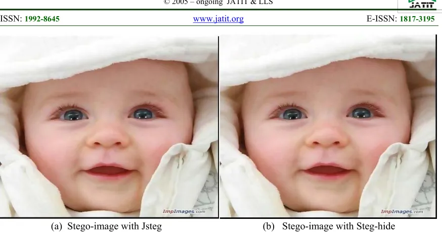
(a) Stego-image with Jsteg (b) Stego-image with Steg-hide
[image:20.612.93.515.288.604.2]Figure 9: Stego- image produced by transfer domain techniques
Figure 10: Comparison of embedding capacity
0 200000 400000 600000 800000 1000000 1200000 1400000 1600000 1800000
N=250 N=500 N=1024 N=2048
Image Size
Embedding Capacity
LSB Substitution
Distortion
Jsteg
Figure 11: Comparison of Mean Square Error
Figure 12: Comparison of PSNR for 4 techniques
0.00E+00 1.00E‐05 2.00E‐05 3.00E‐05 4.00E‐05 5.00E‐05 6.00E‐05 7.00E‐05 8.00E‐05 9.00E‐05 1.00E‐04
N=250 N=500 N=1024 N=2048
Image Size
Mean Square Error
LSB Substitution
Distortion
Jsteg
Steghide
0 20 40 60 80 100 120 140 160 180
N=250 N=500 N=1024 N=2048
Image Size
PSNR
LSB Substitution
Distortion
Jsteg