ISSN: 1992-8645 www.jatit.org E-ISSN: 1817-3195
A NEW APPROACH ON STEP CLUSTERING BASED
GREEDY ROUTING IN
VEHICULAR AD HOC NETWORKS
1M. JAGADEESAN, 2DR .C. CHANDRASEKAR, 3DR.K.JAYASUDHA
1
Assistant Professor, Department of Computer Applications, Kongu Engineering College, Perundurai, Tamil Nadu, India.
2
Professor, Department of Computer Science, Periyar University, Salem, Tamil Nadu, India.
3
Assistant Professor, Department of Computer Science,Thiruvalluvar Govt Arts College,Rasipuram, Tamil Nadu, India
E-mail: 1 [email protected], [email protected],[email protected]
ABSTRACT
VANETs are recent mobile wireless ad hoc networks which plays an important role in communications and various commercial applications. Routing of data is a challenge because of moving of the nodes ie., vehicles. Then the disconnection in between the nodes are always not predictable. The node which we are sending may be at our communication range at that moment, but after the sending of packet, due to some circumstances it may not reach the correct target. In the mean time the target node may go out of the transmission range. This happens due to many reasons like low packet delivery, increased packet overhead or routing overhead. In this paper we propose SCBGR(Step Clustering Based Greedy Routing) which is a position based routing algorithm which uses weight score method for efficient packet forwarding. We had used ns2.33 simulator. The routing overhead has been reduced considerably comparing to the recent routing protocols. The simulation results shows that SCBGR has overcome the limitations of the previous protocols.
Keywords : Vehicular Ad hoc Networks, Greedy Position Based Routing, Step Clustering, SCBGR
1. INTRODUCTION
Communication between vehicles is an advancement in technology now a days. It is providing an intelligent service in between passengers and drivers now a days. Vanet has been providing communication in between vehicles as well as to other vehicles also. Here vanet uses the radio frequency ranges for communication purposes. The distance frequency varies from one country to another. In some of the countries the radio band has been allocated according to the area. In some countries the radio band has been automatically allocated due to safety purposes. Approximately 250 to 300 meters has been kept as the distance measure.
2. SOME OF THE ROUTING PROTOCOLS IN VANET
In this section we have surveyed some of the existing protocols involved in routing.
GPSR (Greedy Perimeter Stateless Routing ): Karp and Kung (2000) in [13] proposes one hop neighbor information. one node sends the data to the another node, then from that node to another node and it continues. Since it takes more time to reach the destination node this model fails.
GSR (Geographic Source Routing): Lochert et al. in [9] proposed GSR, a position-based routing with topological information. This approach employs greedy forwarding along a pre-selected shortest path. But this approach neglects the case that there are not enough nodes for forwarding packets when the traffic density is low.
GPCR (Greedy Perimeter Coordinator
ISSN: 1992-8645 www.jatit.org E-ISSN: 1817-3195 This protocol employs a restricted greedy
forwarding approach along a pre selected path. When choosing the next forwarding node, a coordinator (the node on a junction) is preferred to a non coordinator node, even if it is a non geographical node which is closer to destination. SAR (Spatially Aware Routing): Tian et al (2003) in [12] works using the details available in the street map. It calculates the bends, junctions and no of streets to reach the destination. It takes more calculation time and recovery of data is very difficult in it.
STARP (Spatial and Traffic Aware Routing Protocol): Giudici and Pagani (2005) in [17] uses the differences between the low and high density traffic streets and then forward the packets. But the draw back is wasted bandwidth problems. STARP uses information which is available in city bus routes to identify an anchor path ie.,next forwarding path.
A-STAR (Anchor-based Street andTraffic
Aware Routing): Seet et al. in [10] proposed A-STAR to guarantee an end-to-end connection even in a vehicular network with low traffic density. A-STAR has high connectivity for packet delivery. This position-based scheme also employs a route recovery methodology when the packets are routed by computing a new anchor path from local maximum to which the packet is routed.
GyTARP (Greedy Traffic Aware Routing Protocol): Jerbi et al (2006) in [16] uses the method of junction selection and forwarding. It calculates the number of junctions and then forward the node.The problem isit neglects the low density streets and junctions.So if the node is in low density , junction routing may become difficult.
MDDV (Mobility Centric Data Dissemination Algorithm for Vehicular Networks): To achieve reliable and efficient routing, Wu et al. proposed MDDV [11] that combines geographical forwarding, and trajectory-based forwarding. A forwarding methodology is implied extending from the source to the destination (trajectory-based forwarding), along which a notification that will be forwarded to geographically closer to the destination (geographical forwarding).
VADD (Vehicle-Assisted Data Delivery): To guarantee an end-to-end communication in a sparse network with tolerable delay, Zhao and Cao proposed VADD [8] based on the idea of carry and forward approach by using the next forwarding path which is already predicted, specific to the sparse networks.. This approach predicts the detail about the movement of vehicle in which direction. SADV(Static-Node Assisted Adaptive Routing
Protocol in Vehicular Networks):Ding et al (2007) in [18] uses the idea of keeping of static nodes at the junctions. It stores the data and maintain for certain time limit .If the time lapses or if it is unable to find an optimal path ,the the data loses.
DGRP(Directional Greedy Routing Protocol): DGRP is a position based greedy routing protocol [7], which uses the location, speed and direction of motion of their neighbors to select the next forwarding node. It predicts the position of nodes within the beacon interval whenever it needs to forward a data packet. If link is stable between the forwarding node and its neighbor node is weak, possibility of packet loss is high
PDGRP (Predictive Directional Greedy Routing Protocol): Jiayu Gong proposed PDGRP [14], in which the weighted score is calculated for current neighbours and future neighbors of packet carrier. Here next hop selection is done by prediction and it is not applicable in all the situations. This will lead to low packet delivery ratio, high end to end delay and increased routing overhead.
Cox-Fox Modelling : Youngmin Jeong, JoWoon Chong,Hyundong Shin, and Moe Z. Win in [5] Proposes vehicle’s random locations as a stationary
Cox process with Fox’s H-distributed random
intensity ie., density of vehicles and derive the distributional functions of the ℓth nearest client’s distance from the beacon in such a Fox Cox field of vehicles.Due to some of the dependent factors packet loss occurs.
Back-Bone Assisted Hop Greedy Routing : Ms.Priyanka.G1, Mr.Sundareswari.K in [3] proposes a hop greedy routing scheme that yields a routing path with the smallest count of intermediate intersections. Back bone hop greedy nodes plays a key role in providing the connection between nodes. It tracks the movement of source as well as the destination and sends the packets which is to be forwarded in the next changed direction. Simulation results shows high packet delivery ratio and shorter end-end delay.
3. PROPOSED APPROACH
3.1 SCBGR Algorithm
ISSN: 1992-8645 www.jatit.org E-ISSN: 1817-3195 vehicle has been moving, and the connectivity link
available in between the two nodes. All these datas has been collected from the GPS. Based upon all these factors the next forwarding vehicle is selected .All the nearest vehicles are monitored and the vehicle which is having the highest weight value is selected as the next forwarding vehicle.
The SCBGR has Six operating units. The first is Near Node Identification(NNI), the second one is Distance Calculation(DC), the third one is Direction of Motion (DM), the fourth is Identifying Link Stability(ILS), the fifth is Weighted Calculation(WC) and the sixth is Destination Node Selection(DNS). The NNI is responsible for collection of information of all the nearest nodes present within the transmission range of source node . The DC is in control of calculating the closeness of the next node using distance information from the GPS. DM is responsible to identify the direction of movement of neighbour nodes which is moving towards the destination. The ILS is responsible for identifying the link stability between the source node and its nearest nodes. The WC is responsible to calculate the weighted value and it also identifies the next neighbour node that is having a higher value for further forwarding of a specific packet to the destination. The DNS is responsible to select the forwarding node having higher weighted score.
3.2 Model of SCBGR
The SCBGR algorithm is designed based upon on the following factors: All the vehicles are equipped with GPS receivers, GPS sensors ,on board units(OBU), digital maps, optional sensors and Application units(AU). Location information of all nodes can be collected with the help of GPS receivers. Two types of infrastructure domain access exist: RSU and hot spot. OBUs may also communicate with the Internet via public, commercial, or private hot spots (Wi-Fi). In the absence of RSUs and hot spots, OBUs can use communication capabilities of radio networks
(Global System for Mobile
Communications(GSM)), GPRS, UMTS, WiMax, and Fourth Generation Of Cellular Wireless Standards(4G)) if they are integrated in the OBU.The only communications paths available are via the ad-hoc network . The transmission Range of each node in the vehicular network environment is 250m.This is the maximum transmission range.
3.3 Near Node Identification (NNI)
Near Node Identification is a process of identifying the nearest nodes within the transmission range,.For a particular node, any node within its transmission range is called its neighbor node..Each vehicle carries a neighbor set table within it. It contains all the details of the nearest vehicles. This neighbor set is not a static one because since the vehicles moving around varies time to time, it is always dynamic. But it needs to be updated frequently. The nearest node is found out using the beacon messages and it contains the details of the particular node identifier , location and timestamp.Each and every node informs its presence by sending out beacon messages every µ second.After receiving the beacon message every node updates its neighbor set table.If a known neighbour, times out after (α * µ) seconds without having obtained a beacon (α is the number of beacons which the node is missing ),so that it will be removed from the neighbour set table.
3.4 Distance calculation (DC)
The location where the node is available and the distance information of all the nearest nodes can be located with the help of GPS receivers. communication to neighbour nodes is done by using periodic beacon messages. The neighbour node which is nearer to the destination node is calculated. The closeness of the next nearest node is identified with the help of the mathematical formula shown in Equation (1).
(1)
Here
Dnd is the Shortest distance between neighbor node
n to destination node d
Dsd is the Shortest distance between source node s
to destination node d
3.5 Direction of Motion (DM)
ISSN: 1992-8645 www.jatit.org E-ISSN: 1817-3195 indicates that the vehicle can still move towards the
destination closer along the current direction.
(2)
is the vector of velocity for the neighbor node i is the vector of velocity for theneighbor node i and the destination node d refers to cosine value for the angle made by the vectors
3.6 Identifying Link Stability (ILS)
Link stability is defined as link expiry time, which means maximum time of connection which is maintained between any two neighbour nodes. In order to compute the link expiry time, the motion parameters of any two neighbours are considered. Let N1 and N2 be the two nodes within
the transmission range R and a1’,b1’ and a2’,b2’ be
the coordinates for nodes N1 and N2 with velocity
V1 and V2 and direction and respectively.
Let, after a time interval , the new coordinates be a1 and b1 for N1 and a2 and b2 for N2. For time t , let
d1 and d2 be the distances travelled by nodes N1
and N2.
(3)
LS is the link stability between any two nodes in the time t
R is the transmission range
D is the distance between two nodes at time t 3.7 Weighted Calculation (WC)
The weighted score is calculated by combining the distance, direction of motion and link stability factors of neighbour nodes. A new mathematical model is proposed in Equation (4) to reflect the relationship among these three factors. This mathematical model is used to calculate the weighted score of all nodes present within the R of source/packet carrier node to identify the next suitable hop for forwarding the pac ket to the intended destination.
(4)
Here
Significance of selecting the values: The ρ, ω and λ are the weighted factors. By adjusting the value of ρ, ω and λ, it is possible to make a tradeoff between distance, direction of motion and link stability
when forwarding (i.e. ).
Extremely, this approach will become Greedy Forwarding, if we set = 1, = 0 and . On the contrary, it will become Direction-First Forwarding, if we set = 0, = 1 and . The position information is needed to make precise decision. The distance between the vehicles is calculated using the position information collected from the GPS receivers. In the above Equation (3.7), Dnd is the shortest distance from the
neighbour node n to the destination node d. Dsd is
the shortest distance from the packet carrier node s to the destination node d. Dnd / Dsd is the closeness
of the next hop. The value of (1- Dnd / Dsd ) is very
small when the vehicle is far away from the destination and the weighted score will not be affected much in this case.
3.8 Destination Node Selection (DNS)
Using the formula in Equation (4),the weight score of all the near by nodes within the transmission range R is calculated.The node which is having the highest weight score is selected as the next forwarding hop which is having the higher capacity to reach the destination and forward the packet.DNS is responsible to select the potential node and transmit the packet to the edge node. In DNS, hierarchical clustering technique is used for packet forwarding to improve the efficiency of the existing routing protocol and to avoid the frequent network disconnection.
4. SIMULATION RESULTS AND ANALYSIS
ISSN: 1992-8645 www.jatit.org E-ISSN: 1817-3195
4.1 Revival Mobility model (RMM)
Revival Mobility model (RMM) is used to calculate the moving pattern of vehicles on the roads. This information about the pattern is found out using the GPS facility which is equipped in the vehicle. Here the road have many lanes and cross lanes also. There are number of vehicles moving that varies in the factors like speed, direction etc., Only two directions are considered. North/South for the vertical roads and east/west for Horizontal roads. For the cross lanes the shortest path is calculated. Overtaking of vehicles is allowed here.Packet transmission is possible and it can be done between vehicles moving in both directions, which denote front hopping and back hopping of data packet is possible.
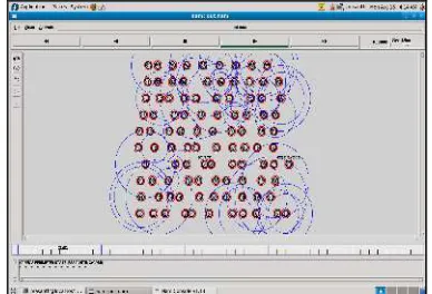
[image:5.612.313.520.60.406.2]The Simulations is done by using Network Simulator (NS-2.33) [10]. GPSR, PDGR and SCBGR approaches were chosen for comparison. The IEEE 802.11 Distributed Coordination Function (DCF) is applied as the Medium Access Control Protocol. The packet size fixed is 512 bytes. The Traffic sources are UDP. At first, the nodes were placed at particular specific locations, and then the nodes moved with varying speeds towards new locations. The nodes moved with speeds up to 30 meter/sec. The ns2.33 implementation of GPSR, PDGR and SCBGR is shown in Figure 1, Figure 2 and Figure 3 respectively.
Figure 1: Gpsr – Ns2 Implementation
Figure 2: Pdgr – Ns2 Implementation
Figure 3: Scbgr – Ns2 Implementation
4.2 Performance Factors to evaluate simulation
In order to evaluate the execution of vehicular ad hoc network routing protocols, the following factors are considered.
End-to-End delay (EED)
[image:5.612.97.291.460.592.2]ISSN: 1992-8645 www.jatit.org E-ISSN: 1817-3195
Table 1: Simulation Parameters For EED Vs Number Of Nodes
Parameter Value
Simulator Simulation Area Number of nodes Mobility of vehicles Maximum Transmission Range
Packet Size MAC Protocol
Vehicle mobility model Simulation duration Performance Metrics
ns - 2.33 1000m x 1000m 20,40,60,80,100,120 5 - 30 (meter/sec) 250m
512 Bytes 802.11 DCF
Revival Mobility Model
120 Seconds End to End Delay
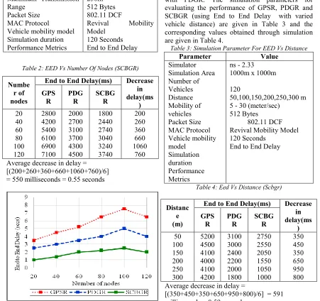
Table 2: EED Vs Number Of Nodes (SCBGR)
Numbe r of nodes
End to End Delay(ms) Decrease in delay(ms ) GPS R PDG R SCBG R 20 40 60 80 100 120 2800 4200 5400 6100 6900 7100 2000 2700 3100 3700 4300 4500 1800 2440 2740 3040 3240 3740 200 260 360 660 1060 760 Average decrease in delay =
[(200+260+360+660+1060+760)/6] = 550 milliseconds = 0.55 seconds
Figure 4: EED Vs. Number Of Nodes (SCBGR)
The End To End Delay from the starting node to the end node is computed for the GPSR , PDGR with SCBGR with the varied No.of nodes ie., vehicle densities which is shown in Fig.4. When the no of vehicles is low, GPSR switches to perimeter mode and it increases the delay of packet transmission much faster than the others. PDGR uses selection of future two neighbours technique.It
[image:6.612.81.532.192.616.2]is difficult sometimes because when the nodes are not available sometimes, there will be an increase in the delay of packet transmission. Our SCBGR uses carry and Forward Strategy. Our algorithm eliminates the selection of unnecessary nodes as the next forwarding node. So it automatically decreases the end to end delay. By using SCBGR, the average delay is reduced to 0.55 seconds in comparison with PDGR. The simulation parameters for evaluating the performance of GPSR, PDGR and SCBGR (using End to End Delay with varied vehicle distance) are given in Table 3 and the corresponding values obtained through simulation are given in Table 4.
Table 3: Simulation Parameter For EED Vs Distance
Parameter Value
Simulator Simulation Area Number of Vehicles Distance Mobility of vehicles Packet Size MAC Protocol Vehicle mobility model Simulation duration Performance Metrics
ns - 2.33 1000m x 1000m
120
50,100,150,200,250,300 m 5 - 30 (meter/sec)
512 Bytes
802.11 DCF Revival Mobility Model 120 Seconds
End to End Delay
Table 4: Eed Vs Distance (Scbgr)
Distanc e (m)
End to End Delay(ms) Decrease in delay(ms ) GPS R PDG R SCBG R 50 100 150 200 250 300 5200 4500 4100 4000 4100 4200 3100 3000 2400 2200 2000 1800 2750 2550 2050 1550 1050 1000 350 450 350 650 950 800 Average decrease in delay =
ISSN: 1992-8645 www.jatit.org E-ISSN: 1817-3195
Figure 5: EED Vs. Distance (SCBGR)
[image:7.612.86.528.71.270.2]The EED from the source node to the destination node is calculated for GPSR, PDGR and SCBGR with the varied vehicle distances and it is shown in figure 5.GPSR and PDGR always select the immediate next neighbour and also future two neighbours respectively to forward the packet. Both use only the nearest available node which is available less than 100m from the source/packet carrier node to forward the data packet. So the coverage area is decreased (i.e. less than 100m).This increases the average number of hops to transmit the packet to the destination, which leads to high end to end delay. Based on the weighted score, SCBGR always selects the neighbour node from the mini clusters C1, C2, C3, C4 and C5 and it increases the coverage area (i.e. 200m to 250m). So the end-to end Delay in Step Clustering Based Greedy Routing in Vehicular Ad Hoc Networks is comparatively small with GPSR and PDGR. when the transmission range is between 200m and 250m respectively. By using SCBGR, the average delay is reduced to about 0.59% in comparison with PDGR. The simulation parameters for evaluating the performance of GPSR, PDGR, SCBGR (using EED with varied mobility of nodes) are given in Table 5 and the corresponding values obtained through simulation are given in Table 6.
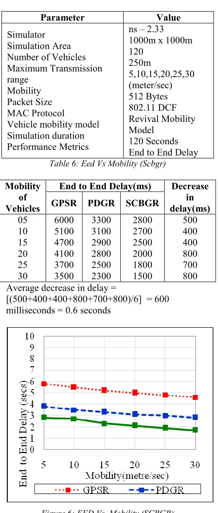
Table 5: Simulation Parameter For EED Vs Mobility
Parameter Value
Simulator Simulation Area Number of Vehicles Maximum Transmission range
Mobility Packet Size MAC Protocol
Vehicle mobility model Simulation duration Performance Metrics
ns – 2.33 1000m x 1000m 120
250m
5,10,15,20,25,30 (meter/sec) 512 Bytes 802.11 DCF Revival Mobility Model
120 Seconds End to End Delay
Table 6: Eed Vs Mobility (Scbgr)
Mobility of Vehicles
End to End Delay(ms) Decrease in delay(ms) GPSR PDGR SCBGR
05 10 15 20 25 30
6000 5100 4700 4100 3700 3500
3300 3100 2900 2800 2500 2300
2800 2700 2500 2000 1800 1500
500 400 400 800 700 800 Average decrease in delay =
[image:7.612.307.531.104.630.2][(500+400+400+800+700+800)/6] = 600 milliseconds = 0.6 seconds
Figure 6: EED Vs. Mobility (SCBGR)
[image:7.612.311.526.440.617.2]ISSN: 1992-8645 www.jatit.org E-ISSN: 1817-3195 loss in GPSR and PDGR. By using SCBGR, the
neighbour node with appropriate weighted score was selected as next hop to forward the packet. So the packet loss is minimized considerably and the end to end delay is minimized. By using SCBGR, the average delay is reduced to about 0.6 seconds in comparison with PDGR.
5. CONCLUSION AND FUTURE EXTENSIONS
Here we have analyzed various routing protocols of vanets. All the previous routing protocols in vanets are well analyzed. We have given all their possible contributions and Limitations. By using the uniqueness features of VANETs, we have suggested Revival Mobility Model.A new position based greedy routing approach which is named as SCBGR is introduced. Comparing our proposed SCBGR approach with other existing routing protocols, it shows that our routing algorithm is better than other routing algorithms in VANET. Our simulation results show that SCBGR outperform GPSR and PDGR significantly in the terms of end to end delay minimization.
In future our approach will proceed towards the environment characteristics in the city and various types of available Mobility Models. In additional we have planned to include the privacy and security mechanisms. Further our approach requires modifications by taking into consider the city environment characteristics and distinct mobility models . Other than that we have also planned to include the integration of privacy and security mechanisms and the establishment of first priority routes for emergency and safety messages. Since experimental calculation of VANETs is expensive, simulations technique can be improved.
REFERENCES
[1] P. Rawat, K.D. Singh, H. Chaouchi, J.M. Bonnin, Wireless sensor networks: a survey on recent developments and potential synergies, J. Supercomput. 66 (2013) 1–48. [2] K.D. Singh, P. Rawat, J.-M. Bonnin, Cognitive
radio for vehicular ad hoc networks (CR-VANETs): approaches and challenges, EURASIP J. Wireless Commun. Network 49 (2014) (2014).
[3] Ms.Priyanka.G1, Mr.Sundareswari.K2 ,” Back-Bone Assisted Hop Greedy Routing in Vanets “, International Journal of Innovative Research in Computer and Communication
Organization) Vol.2, Special Issue 1, March 2014.
[4] M. Benamar, S. Ahnana, F.Z. Saiyari, N. Benamar, M.D. El Ouadghiri, J.-M.Bonnin, “Study of VDTN routing protocols performances in sparse and dense traffic in the presence of relay nodes “ , J. Mob. Multimedia, 10 (1&2), 2014, 78–93.
[5] Youngmin Jeong, JoWoon Chong, Hyundong Shin, Moe Z. Win,” Intervehicle Communication: Cox-Fox Modeling “ , Ieee Journal On Selected Areas In Communications /Supplement, Vol. 31, No. 9, September 2013.
[6] Hannes Hartenstein and Kenneth P. Laberteaux,” A Tutorial Survey on Vehicular Ad Hoc Networks”, IEEE Communication Magazine, June 2008.
[7] Rupesh Kumar, S.V.Rao. “Directional Greedy Routing Protocol (DGRP) in Mobile Ad hoc Networks”, International Conference on Information Technology, 2008.
[8] J. Zhao and G. Cao. “VADD: Vehicle-Assisted Data Delivery in Vehicular Ad Hoc Networks”, InfoCom 2006.
[9] C. Lochert, M. Mauve, H. Fler, H. Hartenstein. “Geographic Routing in City Scenarios” (poster), MobiCom. 2004, ACM SIGMOBILE Mobile Computing and Communications Review (MC2R) 9 (1), pp. 69–72, 2005.
[10] B.-C. Seet, G. Liu, B.-S. Lee, C. H. Foh, K. J. Wong, K.-K. Lee. “A-STAR: A Mobile Ad Hoc Routing Strategy for Metropolis
Vehicular Communications”,
NETWORKING 2004.
[11] H. Wu, R. Fujimoto, R. Guensler and M. Hunter. “MDDV: A Mobility-Centric Data Dissemination Algorithm for Vehicular Networks”, ACM VANET 2004.
[12] C. Lochert, H. Hartenstein, J. Tian, D. Herrmann, H. Fubler, M. Mauve: “A Routing Strategy for Vehicular Ad Hoc Networks in City Environments”, IEEE Intelligent Vehicles Symposium (IV2003).
ISSN: 1992-8645 www.jatit.org E-ISSN: 1817-3195 [14] Jiayu Gong, Cheng-Zhong Xu and James
Holle. “Predictive Directional Greedy Routing in Vehicular Ad hoc Networks”, (ICDCSW’ 07).
[15] The Network Simulator: ns2, http: //www.isi.edu/nsnam /ns/."
[16] Jerbi, M., Senouci, S.M. and Meraihi, R. “GyTAR: Improved Greedy Traffic Aware Routing Protocol for Vehicular Ad Hoc Networks in City Environments”, Proceedings of the Third International Workshop on Vehicular Ad Hoc Networks, September 29, Los Angeles, California, USA, pp.8-89, 2006. [17] Giudici, F. and Pagani, E. “Spatial and Traffic-Aware Routing (STAR) for Vehicular Systems”, Proceedings of the First International Conference on High
Performance Computing and
Communications, Berlin, Germany, Vol.3726, pp.77-86, 2005.