Comparative Study of Flat Slab & Conventional Slab Structure Using
Software
Mr. Balasaheb Navale
1Dr. M. R. Wakchaure
2 1PG Student
2Associate Professor
1,2
Department of Civil Engineering
1,2AVCOE, Sangamner, India
Abstract— In today’s construction industry, the use of flat slab is quite common which enhances the weight reduction, speed up construction, and economical. Similarly, from the beginning conventional slab has got place in providing features like more stiffness, higher load carrying capacity, safe and economical also. As the advancement era began practice of flat slab becomes quite common. In the present dissertation work a G + 7 commercial multi-storeyed building having flat slab and conventional slab has been analyzed for various. In the present work the storey shear of flat slab, the axial forces on flats slab building, the difference in storey displacement of flat and conventional building are approximately calculated by using software. The main objective of the present work is to study the behavior of flat slab structure and conventional slab structure for a commercial building in seismic zones (III) and compare the behavior of the building for the parameters like storey displacement, shear force, storey drift, base shear, axial force, bending moment and axial load on the footing under varying load conditions.
Key words: Flat Slab, Drop, Conventional Slab, Storey Shear, Storey Displacement, Axial Forces, Base Shear, Axial Load
I. INTRODUCTION
Flat slab is system of construction is one in which slab is directly rest on the column. The slab directly rests on the column and load from the slab is directly transferred to the columns and then to the foundation. To support heavy loads, the thickness of slab near the support is increased and these are called drops and columns are generally provided with enlarged heads called column heads or capitals. Because of absence of deep beam flat slab building structures are more significantly flexible than conventional concrete structures, thus becoming more vulnerable to seismic loading. Thus, the seismic analysis of these structures is necessary to know the vulnerability of these structures to seismic loading. It is important to know the behavior of the building structure with the conventional slab beam method and flat slab structure for a G+7 commercial building which is imposed with varying load conditions.
The term flat slab means a reinforced concrete slab with or without drops, supported generally without beams, by columns with or without flared column heads. A flat slab may be solid slab or may have recesses formed on the soffit so that the soffit comprises a series of ribs in two directions.
Column strip - Column strip means a design strip having a width of 0.25I, but not greater than 0.25l, on each side of the column center- line, where I is the span in the direction moments are being determined, measured center to center of supports and 1, is the-span transverse to l measured center to center of supports.
A. Middle Strip
Middle strip means a design strip bounded on each of its opposite sides by the column strip.
B. Panel
Panel means that part of a slab bounded on-each of its four sides by the center-line of a column or center-lines of adjacent-spans.
The thickness of the flat slab shall be generally controlled by considerations of span to effective depth ratio. For slabs with drops conforming to the below mentioned clause, span to effective depth ratios shall be applied directly; otherwise the span to effective depth ratios obtained in accordance with provisions shall be multiplied by 0.9. For this purpose, the longer span shall be considered. The minimum thickness of slab shall be 125 mm.
C. Drop Panels
The drops when provided shall be rectangular in plan, and have a length in each direction not less than one- third of the panel length in that direction. For exterior panels, the width of drops at right angles to the non- continuous edge and measured from the center-line of the columns shall be equal to one-half the width of drop for interior panels
D. Column Head
Where column heads are provided, that portion of a column head which lies within the largest right circular cone or pyramid that has a vertex angle of 90”and can be included entirely within the outlines of the column and the column head, shall be considered for design purposes. Certain amount of negative moment is transferred from the slab to the column at the support. to resist this negative moment the area at the support needs to be increased. This is facilitated by providing column capital/heads.
II. EXPERIMENTAL METHODOLOGY AND MATERIAL
PROPERTIES
The project study involved two stages. The primary data was gathered through a Literature survey targeted by web searches and review of eBooks, manuals, codes and journal papers. After reviewing the problem statement is defined and model preparation is taken up for detail study and analysis purposes. This project execution follows the flow chart given below:
1) Literature Collection
2) Review on Flat Slabs and Types of Flat Slabs 3) Define Problem Statement
4) Model Input Generation with Cad Files 5) Material Specifications
6) Modeling and Analysis on Software
8) Results and Discussions 9) Conclusion
A. Finite Element Method
The finite element method is a numerical technique to find approximate solutions of partial differential equations. Finite element method allows for detailed visualization and indicates the distribution of stresses and strains inside the body of a structure. The analysis of flat and conventional slab structure has been done by using software package. Before analysis all the required elements of the structure need to be defined earlier like material properties, loads, load combinations, size of members, response spectrum etc. once the analysis has been done we can extract the results like displacement, storey shear, bending moment, drift ratio, axial forces for comparing the performance of flat and conventional slab building.
B. Software Analysis and Design Procedure 1) Define Plan Grids and Story Data 2) Define Material Properties 3) Define Frame Sections 4) Define Slab Sections 5) Define Load Cases
6) Draw Beam Objects (Frame Members) 7) Draw Column Objects (Frame Members) 8) Assign Slab Sections
9) Assign Restrains 10) Assign Slab Loads
11) View Input Data in Tabular Form 12) Run the Analysis
13) View Analysis Results Graphically 14) Design Concrete Frame Element
C. Material Properties & Loads
This work has been analyzed using software. For the analysis the material properties like grade of concrete, steel, density, modulus of elasticity must be defined initially. And, the various loads like dead, live, SDL (Superimposed Dead Load), seismic load needs to be defined earlier.
Superimposed dead load of 2.5 kN/m2 for typical floor and 3 kN/M2 for roof is considered for the analysis. Live load of 4 kN/m2 on floors & 1.5 kN/m2 on terrace floor is provided in accordance to IS 875 (Part2).
For seismic weight, total dead load and 50 percent of live load is considered as per Table 8 of IS 1893 (Part1): 2016. For calculation of seismic weight, no roof live load is taken.
Grade of concrete: M25
Grade of steel: Fe 500
Modulus of elasticity E: 2 x 10⁵ N/mm2
Live load on typical floor: 4.0 kN/m2
Live Load on Roof = 1.5 kN/m2
SIDL: 2.5 kN/m2 on floors and
SIDL = 3.0 kN/m2 on roof (for waterproofing)
D. Model Description and Structural Plan details of Flat Slab
Number of Stories G + 7
Height of each storey 3.6 m
Total height of building 28.8 m
Number of bay’s along X 4
Number of bays along Y 4
Column Size (600 x 600) mm
Beams Size (300 x 450) mm
Drop thickness 450 mm
Slab Thickness 200 mm
Table 1: Model Description and Structural Plan details of Flat Slab Structure
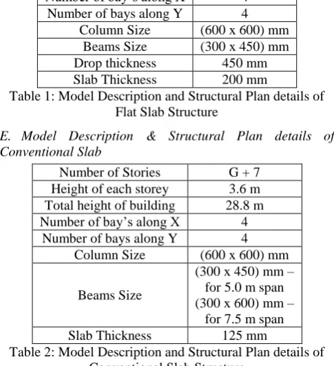
E. Model Description & Structural Plan details of Conventional Slab
Number of Stories G + 7
Height of each storey 3.6 m
Total height of building 28.8 m
Number of bay’s along X 4
Number of bays along Y 4
Column Size (600 x 600) mm
Beams Size
(300 x 450) mm – for 5.0 m span (300 x 600) mm –
for 7.5 m span
[image:2.595.307.550.76.342.2]Slab Thickness 125 mm
Table 2: Model Description and Structural Plan details of Conventional Slab Structure
F. Earthquake Considerations
The structures are more vulnerable to lateral loads, as the height of building increases the structures becomes flexible and prone to damage. Hence lateral loads are mainly derived from seismic and wind loads for which structure needs to be analyzed:
Seismic Zone III
Zone Factor Z 0.16
Importance Factor I 1
Response Reduction Factor 3
Damping Ratio 0.05
Type of Soil Medium
Table 3: Earthquake Considerations
G. Load Combinations
The structure is analyzed considering proper ratios of the applied dead loads, live loads and seismic loads. The Load combinations are given in IS 1893 (part-1):2016. As the seismic loads are assigned in both X-Horizontal and Y-Vertical direction so E. Lx and E. Ly should be considered. Load combinations considered for the analysis and comparison is shown in Table No. 4.
S. No Loads Factors
1 Dead load 1.5
Superimposed dead load – SIDL 1.5
2
Live load 1.2
Superimposed Live load – SIDL 1.2
Live load 1.2
Seismic Load (X Direction) ±1.2
3
Dead load 1.2
Live load 1.2
Seismic Load (Y Direction) ±1.2
4 Dead Load 1.5 1.5
Seismic Load (X Direction) ±1.5
Seismic Load (Y Direction) ±1.5
6 Dead Load 0.9
Seismic Load (X Direction) ±1.5
7 Dead Load 0.9
Seismic Load (Y Direction) ±1.5 Table 4: Load Combinations
H. Load Patterns
The following load patters are taken into consideration for the modelling and analysis of the commercial building using software.
Name Type Self-Weight
Multiplier
Auto Load
Dead Dead 1
Live Live 0
Eq.x Seismic 0 IS1893
2016
Eq.y Seismic 0 IS1893
2016
SIDL Superimposed
Dead 0
Table 5: Load Patterns
III. RESULTS & DISCUSSION
A. Total Mass of the Building
The mass of the building being designed controls seismic design in addition to the building stiffness, because earthquake induces inertia forces that are proportional to the building mass. Designing buildings to behave elastically during earthquakes without damage may render the project economically unviable.
Graph 1: Comparison of Total Mass of the Building
B. Base Shear Comparison
Base shear is the maximum expected lateral force that will occur due to seismic ground acceleration at the base of the structure.
[image:3.595.52.277.62.138.2]Base shear is an estimate of the maximum expected lateral force that will occur due to seismic ground motion at the base of a structure.
[image:3.595.56.283.434.562.2]Fig. 1: Lateral Force Distribution at various floor levels for flat slab structure
Fig. 2 shows the lateral force distribution at various floor levels for Flat Slab Structure
Graph 2: Comparison of Base Shear of the Structures
C. Storey Drifts
Storey drift is defined as difference between lateral displacements of one floor relative to the floor below. I.S. 1893-2002: The storey drift in any storey due to the minimum specified design lateral force with partial load factor 1.00 shall not exceed 0.004 times the storey height. In this case storey height is 4.200 m.
Graph 3: Comparison of Storey Drift of the Structures
D. Storey Shear
In one method of designing a structure to have seismic resistance, the design seismic force is presumed to be applied at each floor level. The floor slab is very stiff in its own plane, because the large width of the structure. Hence, all floor slabs are presumed to simply move laterally in their own planes under seismic forces. The design seismic force to be applied at each floor level is called storey shear. It is a fraction of the total dead load and a part of the live load acting at each floor level.
Graph 4: Comparison of Storey Shear of the Structures
E. Axial Forces
The following graph compares the axial forces at each floor for the flat slab structure and conventional slab structure at Station 0.
Graph 5: Comparison of Axial Force of the Structures Bending Moment
The following graph compares the bending moment for the flat slab structure and conventional slab structure at Station 0 for all the stories.
Graph 6: Comparison of Bending Moment of the Structures
F. Axial Force at the base of the column – i.e. at the Footing Axial Forces at the base of the footing govern stresses at the base of the structure and the footing design. Graph 7: Shows the comparison of the axial force at each column for the flat slab structure and conventional slab structure.
IV. CONCLUSION
Based on analysis and cost estimate of flat slab building and Conventional RCC slab structure, the following conclusions are drawn:
The time period will be maximum at mode 1, 2 and 3. After mode 3, time period will reduce drastically. The natural time period increases with the increase in the number of floors.
The sway of the building/structure is directly proportional to the number of floors wherein the sway increases with the increase in the height of the structure. Sway at terrace level is maximum for both types of building. Accordingly, the column behavior changes as height of the building increases. The columns have been designed for the combination of dead load and earthquake load for all cases and the load combination 1.5[DL ± EX] is the most critical.
The slab drops are an important criterion which is a governing factor in increasing the shear strength of the slab. Slab drops help in increasing the overall capacity and sturdiness of the flooring system beneath the vertical loads. The column heads in the flab helps in increasing the shear strength of the slab and reduces the moment of the slab by reducing the clear or effecting span of the structure.
It is concluded that flat Slabs without drop panels can be built at a very fast pace as the framework of structure is simplified with ease of construction and erection of the structure.
Flat slab construction usually reduces floor-to –floor height especially in the absence of false ceiling as flat slab construction does act as limiting factor on the placement of horizontal services and partitions. This can prove rewarding in case of lower building elevation, decreased cladding expenditure and pre-fabricated facilities.
In case the client plans to change the interior of the structure and wants to use the space to suit the need, flat slab construction is the perfect choice as it offers the flexibility to the possessor. This flexibility is possible due to the use of square lattice and absence of beam which usually makes channeling of services and allocation of partitions difficult.
The reinforcement detailing of flat slab is easy to place and thus helps in speedy construction with less complexities in the execution. The formwork required for the construction of flat slab is less thus proving it cost effective as compared to the conventional slabs.
The following conclusions are drawn from the comparative analysis of the two structures:
The storey drift of conventional slab is more than flat slab and by 7.62%
The storey shear of flat slab is more as compared to conventional slab by 7.76%
Base Shear for flat slab is more than that of the conventional slab by 7.79%
Axial Forces for the flat slab are more compared to conventional slab maximum by 11.6%
The Bending Moment is more for flat slab than that of conventional slab by 49.68%
Axial forces on the footing is more on the flat slab structure by 11.6% as compared to conventional slab structure.
REFERENCES
[1] Rasha T.S. Mabrouk, Amr Bakr, Hany Abdalla, Effect of flexural and shear reinforcement on the punching behavior of reinforced concrete flat slabs - Alexandria Engineering Journal (2017) 56, 591–599 | June 2017. [2] Szczepan Wolinski, Robustness and vulnerability of flat
slab structures - International Conference on Analytical Models and New Concepts in Concrete and Masonry. Structures AMCM -193, 88 – 95 | 2017.
[3] Khwaja Moinuddin Khan, M. Jeelani, Analysis and Design of Flat Slabs in Commercial Building by using Software- International Research Journal of Engineering and Technology (IRJET) e-ISSN: 2395-0056 Volume: 05 Issue: 05 | May-2018.
[4] Kavish Patwari, 2L. G. Kalurkar (2016)- Comparative Study of Flat Slab Building with and Without Shear Wall to earthquake Performance- International Journal of Scientific Development and Research (IJSDR) www.ijsdr.org
[5] Amit A. Sathawane & R.S. Deotale -Analysis and Design of Flat Slab and Grid Slab and Their Cost Comparison- International Journal of Advanced Technology in Civil Engineering, ISSN: 2231 –5721, Volume-1, Issue-2, 2012.
[6] M.G. Sahab, A.F. Ashour, V.V. Toropov (2005) - Cost optimization of reinforced concrete flat slab buildings- Engineering Structures 27 (2005) 313–322.
[7] Nishant S. Borse, Vijaykumar P. Bhusare (2017)- Review on Seismic Performance of Flat Slab Structures by Evaluation of R Factor- IJSTE - International Journal of Science Technology & Engineering | Volume 3 | Issue 09 | March 2017 ISSN (online): 2349-784X.
[8] Sumit Pahwa, Vivek Tiwari, Madhavi Prajapati (2015)- Comparative Study of Flat Slab with Old Traditional Two-Way Slab- International Journal of Latest Trends in Engineering and Technology (IJLTET)Vol. 4
[9] Stability and ductility of steel structures Lisbon, Portugal, September 2006 review: the direct strength method of cold-formed steel member design.
[10]Proceedings of the 6th Asia-Pacific Structural Engineering and Construction Conference (APSEC 2006), 6 September 2006, Kuala Lumpur, Malaysia typical tests on cold-formed steel structures.
[11]Scientific Research and Essays 18 July 2010 Academic Journals Linear buckling optimization and post-buckling behavior of optimized cold formed steel members. [12]Journal Technology, Jun. 2005 University Technology
Malaysia. Performance of locally produced cold-formed steel sections for roof.
[13]Darcy, G. and Mahendran, M. (2008). “Development of a new cold formed steel building system”, Advances in Structural Engineering, Special issue: Advances in Cold-Formed Steel Structures, Accepted manuscript.
[16]Mohana H.S, Kavan M.R “Comparative Study of Flat Slab and Conventional Slab Structure Using Software for Different Earthquake Zones of India” International Research Journal of Engineering and Technology (IRJET) Volume: 02 Issue: 03 | June-2015.
[17]P.V.L. Narasinga Rao, S. Sai Nithin, Sk. Javed Ali and V.S. Vani – “Comparative Study on Design of Slabs” International Journal of Advances in Scientific Research and Engineering (IJASRE) - Volume 4, Issue 3 March – 2018
[18]B. Anjaneyulu, K Jaya Prakash – “Analysis and Design Of Flat Slab By Using Etabs Software” – International Journal of Science Engineering And Advanced Technology – Volume 4, Issue 2 – February 2016 [19]Amrut Manvi1, Sandeep Gouripur, Pooja Sambrekar,
Ramanjeetkaur, Dr. Kishor S. Kulkurni – “COST COMPARISON BETWEEN CONVENTIONAL AND FLAT SLAB STRUCTURES” - International Research Journal of Engineering and Technology (IRJET) - Volume: 02 Issue: 03 | June-2015.
[20]Anghan Jaimis, Mitan Kathrotiya, Neel Vagadia, Sandip Mulani – “Comparative Study of Flat Slab and Conventional Slab using Software Aid” - Global Research and Development Journal for Engineering | Recent Advances in Civil Engineering for Global Sustainability | March 2016.