Cascaded Nonlinear Adaptive Predictive Control based
Adaptive Flux Observer of Induction Motor
ABSTRACT
This paper present a new advanced control algorithm based on continuous minimization of predicted tracking errors, to achieve torque, rotor speed and rotor flux amplitude tracking objectives. This algorithm called a new Adaptive Nonlinear Predictive Control to induction motor drive uses a combination of the adaptive observer for rotor flux and Cascaded Nonlinear Predictive Control technique. The variables to be controlled are the rotor speed and the rotor flux norm, required to implement the predictive control algorithm is estimated by flux observer. The parameters identified adaptively are stator and rotor resistance which vary with motor temperature using the adaptive rotor flux observer. A stability of the proposed adaptive flux observer will be proved by the Lyapunov's theorem. Simulations are carried out in order to show the effectiveness of the drive and the robustness to parameters variations.
Keywords
Cascaded Nonlinear Predictive Control, Nonlinear Control, Induction Motors, Adaptive Flux Observer.
1.
INTRODUCTION
For over fifty years, DC motors have been widely used in variable speed drives applications principally due to their fast torque response, high precision of regulation and the possibility to use these motors in whichever mode of operation [1]. However DC motors with drawbacks of spark, corrosion and necessity of maintenance, this motor has been replaced by AC induction motors (IMs)[2].Induction motors (IMs) are widely used in many industrial applications due to their mechanical robustness and low cost [1,2]. However, it is known that the control of induction motors is relatively difficult compared to other kinds of motors, such as DC motors and synchronous motors due to their coupled and nonlinear model [1-4].
To solve this problem and achieve high performance, field-oriented control (FOC) schemes have been proposed by F. Blaschke in 1972 [4]. This method can provide at least the same performance from an inverter-driven induction motor as is obtainable from a separately excited DC motor [5]. To improve the Field Oriented Control, in the last years, many strategies have been studied to control induction motor. [7] Among recent studies on input-output linearization, in [8] has proposed a controller designed to track torque and rotor flux references, in [9] have developed an input-output decoupling controller which decouples the regulation of the rotor speed and the rotor flux norm.
The predictive control method is traditionally used for industrial process control and a large number of
implementation algorithms have been presented in literature such as extended prediction self adaptive control, generalized predictive control and unified predictive control [10], the basic idea of GPC presented by Clarke et al. 1987 in [11].Predictive Algorithms have already been used for controlling industrial plants, as related in [12] the author present a novel algorithm called Generalized Predictive Control (GPC) is shown to be particularly effective for the self-tuning control of industrial processes. In [13] is proposed a control approach where the direct power control is combined with predictive selection of a voltage-vector of inverters. In [14], the use of low-frequency predictive current control is proposed for a single-phase cascaded H-bridge multilevel rectifier.
Various proposals have been made for the use of predictive algorithms to control electric motors, especially induction motors (IM). The majority of these algorithms involve vector control algorithms and independent strategies to control the rotor flux and speed [15]. A model-based predictive control of rotor flux and speed of a vector-controlled induction motor is presented in [16], a state space approach is employed for modelling a rotor-flux oriented induction motor. Generalized predictive control of linear systems has received considerable attention in the last decade due to its robustness with respect to parameters variations. Much effort has been done to extend GPC to nonlinear system [17].
The classical GPC had been developed with linear plant for prediction model which leads to a formulation that can be solved analytically if the process is defined by a nonlinear model, [18] the use of linear model predictor becomes impractical, and the design of nonlinear predictor and nonlinear algorithm for optimization are necessary [19]. A nonlinear generalized predictive control (NGPC) of induction motor drive is presented in [20]; the predictive control algorithm is implemented using a model of the motor in fixed stator reference frame. The task of the controller is to track the desired speed and flux profiles. Rotor flux information required to implement the predictive control algorithm is estimated using Kalman Filter algorithm.
This paper is organized as follows. The mathematical model of the induction motor is developed in Section 3, while Section 4 describes a Cascaded Nonlinear Predictive Control scheme to simultaneous control of the electromagnetic torque, the norm of rotor flux and rotor speed, (Kalman filter used for the estimation of rotor flux).
In Section 5 we present a new advanced control algorithm based on continuous minimization of predicted tracking errors, to achieve load torque, rotor speed and rotor flux amplitude tracking objectives. This algorithm called a new Adaptive Cascaded Nonlinear Predictive Control uses a
S.Meziane
Department of Electrical Engineering, Souk AhrasUniversity, Algeria
R.Toufouti
Department of Electrical Engineering, Souk Ahras, University,Algeria
A.Merabet
Division of Engineering,Saint Mary’s University Halifax, Nova Scotia,Canada
H.Benalla
Department of Electrical Engineering Constantinecombination of the adaptive observer for rotor flux and Cascaded Nonlinear Predictive Control. Finally, the performance of the proposed drive control system is verified by simulation.
2.
NONLINEAR INDUCTION MOTOR
MODEL
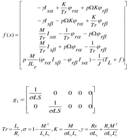
The induction motor consists of three-phase stator windings and a rotor with short cut windings. Since the torque produced is a function of the difference between the mechanical speed and the angular speed of the supplied stator voltage, this results in a nonlinear model. To reduce the complexity of a three-phase model, an equivalent two-phase representation is chosen [5]. For the FOC this two-phase model is usually transformed in a rotating (d,q) reference frame [9]. This transformation is a source of problems but usually the FOC approach does not allow control the model in a stator fixed (,) reference frame. Using nonlinear feedback allows to contorted the model in the stator fixed (,) reference frame avoiding the transformation in a rotating reference frame. The complete model in stator fixed (,) reference frame can is written form for a control in speed and flux [7-10]:
2 2 2
1 1
)
(
)
(
)
(
.
)
(
r rx
h
x
h
y
t
u
g
x
f
x
S
(1)
Where
x
[
I
sI
s
r
r
]
T;
T s s uu
u[ ]
) (
1 ) (
1 1
) (
f L T J s I r s I r r JL
M p
r Tr r p s I Tr M
r p r Tr s I Tr M
r Tr
K r K p s I
r K p r Tr
K s I
x f
0 0 0 1 0
0 0 0 0 1
1
LS LS g
2 2 2
, ,
1 ,
r s r s r
s r
s r
r
L L
M R L Rs L
L M K L L
M R
L Tr
Is, Is is denote the stator currents, s, s the rotor fluxes,
us, us the stator voltages, Ls , Lr the stator and rotor inductance, Rs , Rr the stator and rotor resistance, J the inertia of the machine, M the mutual inductance, f the friction
coefficient, p the poles pair number, TL the load torqu
e, and
finally Tr is the rotor time constant [17].
3.
CASCADED NONLINEAR
PREDICTIVE CONTROL OF
INDUCTION MOTOR
The objective of this structure is to simultaneous control of the electromagnetic torque, the norm of rotor flux and rotor speed using the cascaded structure decomposed into two sub-systems in a cascaded form as shown in Fig.1.
CNP1
sa
V
sb
V
abc
*
abc
sabc
V
sabc
I
*
r
s
I
s
V
/// ///
///
eref
T
sc
V
CNP2
Kalman
Filter
External loop
Internal loop
r
ˆ
VSI
Based
SVM
e
T
*
s
V
*
s
V
[image:2.595.323.541.72.306.2]
In this model the external load torque is considered to be a disturbance. Its amplitude is computed with an disturbance observer developed, from the mechanical equation of the induction motor [16,20].
The two loops of the cascaded structure imply the definition of two G.P.C. algorithms and consequently the minimization of two quadratic cost functions. It is also necessary to define two models, corresponding to the inner and external systems [23]. The external loop controls the speed. The internal loop controls the torque and flux.
Where U is the resulting control signal applied on the induction motor, w1 is the set point "followed" by y1, w2, is the inner signal coming from the minimization of G.P.C.1.
3.1
Internal loop controls the torque and
rotor flux
Considering the electromagnetic torque and rotor flux modulus as outputs of the A.C. drive, the following equations can be derived, with y1 as the torque and y2 as the squared
rotor flux modulus:
2 2 2 2 2 1 1)
(
)
(
)
(
)
(
)
(
r s r s r r r rx
h
x
y
I
I
L
pM
x
h
x
y
(2)
The derivatives Lie of the Electromagnetic torque and rotor Flux, are:
)
(
)
(
)
(
)
(
)
(
)
(
)
(
)
(
1 2 1 1 1 1 1 1t
V
x
h
L
t
V
x
h
L
x
h
L
x
y
x
h
x
y
s g s gf
(3)
)
(
)
(
)
(
)
(
)
(
)
(
)
(
)
(
)
(
)
(
2 2 2 1 2 2 2 2 2 2 2t
V
x
h
L
L
t
V
x
h
L
L
x
h
L
t
y
x
h
L
t
y
x
h
t
y
s f g s f g ff
( 4)
The expansion of the same rth order Taylor series of the
motor outputs y(t+T) with (r1=1 and r2=2 ) in matrix form is
the following :
)
(
2
)
(
)
(
)
(
)
(
)
(
)
(
2 2 2 2 2 1 1 1t
y
T
t
y
T
t
y
T
t
y
t
y
T
t
y
T
t
y
(5)
Using the matrix form, the predicted output is rewritten as:
T
t
u
x
G
t
Y
T
t
y
(
)
(
(
)
(
)
(
))
(6) Where
t g g g g t r rx
h
L
L
x
h
L
L
x
h
L
x
h
L
x
G
x
h
L
x
h
L
x
h
L
x
h
x
h
t
Y
I
T
I
T
I
f f f f f
)
(
0
)
(
0
0
)
(
0
)
(
0
0
0
0
)
(
)
(
0
)
(
)
(
)
(
)
(
)
(
)
2
/
(
2 1 2 1 2 2 2 1 2 1 2 2 2 2 2 2 2Similarly, Yr(t+T) may be expanded in a same rth order Taylor series:
)
(
2
)
(
)
(
)
(
)
(
)
(
)
(
2 2 2 2 2 1 1 1t
y
T
t
y
T
t
y
T
t
y
t
y
T
t
y
T
t
y
r r r r r r r
(7)
The predicted reference trajectory using matrix form as:
)
(
)
(
t
T
Y
t
y
r
r(8) Where
tr r
r r
r
t
y
t
y
t
y
t
y
t
y
t
Y
(
)
1(
)
2(
)
1(
)
2(
)
0
2(
)
For the internal loop the control objective is the tracking of y1
and y2 to desired reference signals yr1 and yr2, along the
interval [t; t + T], That is, the tracking error is defined by:
)
(
)
(
)
(
)
(
)
(
)
(
2 1 2 1 2 1T
t
y
T
t
y
T
t
y
T
t
y
T
t
e
T
t
e
r r
(9)
The cost function to be minimised is then:
)] ( ) ( ) ( ) ( [ )] ( ) ( ) ( ) ( [ 2 1
1 Y t Gt ut Y t Y t G tut Y t
J t r
r
(10) Where dT t T
0The minimization of J with respect to u(t), by setting 0
1
t
J , yield s to an optimal predictive control law:
))
(
)
(
(
)
(
))
(
)
(
(
)
(
t
G
x
G
x
1G
x
Y
t
Y
t
u
rt
t
(11)
Differentiating the output y1, one time and the output y2
twice and by using the above control equation, we can show that the tracking errors dynamics are:
For the torque:
(
)
0
2
3
)
(
1
1
e
t
T
t
e
y y(12)
For the flux:
(
)
0
3
10
)
(
2
5
)
(
2 22
2e
t
T
t
e
T
t
e
y
y y
(13)The above dynamics equations are linear and time invariant. Therefore, the proposed technique leads to feedback linearization and we can easily verify the asymptotic stability of the tracking errors dynamics of the overall system.
3.2
External loop controls the speed
The control objective of the external loop is the tracking of
(t) to a desired reference r(t). A load torque is considered to be a disturbance. A mechanical dynamics model of the motor is described by the following equation:
L
T
J
f
t
J
f
t
y
J
t
(
)
1
1(
)
(
)
(14)The expansion of the same rth order Taylor series of the motor outputs y(t+ T)
)
)
(
)
(
1
(
)
(
)
(
)
(
)
(
)
(
1
T
LJ
f
t
J
f
t
y
J
T
t
T
t
t
T
t
T
t
(15)Similarly, the prediction model for reference trajectory
yr(t+T) can be presented by an expansion of the same r
th
order Taylor series as.
)
(
)
(
)
(
t
T
rt
T
rt
r
S
V
-
-
+
B
+
Adaptive
Observer
-+
+
SI
C
I/S
r
ˆ
Induction
Motor
Adaptation
Mechanism
A
ˆ
The optimal predictive control law is abstained by, (15) et (16), and she given by:
)
(
)
(
)
(
))
(
)
(
(
)
(
t
t
f
t
J
t
C
t
T
J
t
T
e
r
r
r
r (17)Substituting the law control (17) in the mechanical equation (14), the dynamic tracking error is given by:
0
)
(
)
(
(
1
)
(
*
t
t
t
e
r
(18)The equation (19) allows controlling the speed by acting on the torque yl.
dT T t T t T t T t J r t r T )) ( ) ( ( )) ( ) ( ( 2 1 0
2
(19)
4.
ADAPTIVE FLUX OBSERVER
[image:4.595.322.525.70.334.2] [image:4.595.43.286.302.532.2]The parameters are updated only in a powering operation. Figure.2 shows a block diagram of the proposed flux observer with the parameter adaptive scheme.
Fig 2: Block Diagram of Proposed Flux Observer
The full order state observer which estimates the stator current and the rotor flux is written by following equations [27]. The state observer, which estimates the stator current and the rotor flux together, is written as the following equation.
)
ˆ
(
0
1 22 21 12 11 s s s r s r sI
I
G
V
B
I
A
A
A
A
I
(20) Where
Tr r r T s s s T s s
s
V
V
I
I
I
V
,
,
0
1
1
0
1
0
0
1
,
1
1
,
1
1
1 1 122 22 22 21 21 112 12 12 11 11J
I
I
b
I
σ.L
B
J
a
I
a
J
I
T
A
I
a
I
T
M
A
J
a
I
a
J
I
T
.L
σ.L
M
A
I
a
I
σ.T
σ.L
R
A
s r r r r r r r s r r s s
Tg
g
g
g
g
g
g
g
G
3 4 4 3 1 2 2 1M
L
L
c
a
k
c
g
a
a
k
a
ca
k
g
a
k
g
a
a
k
g
r s r r r r r i r r
,
)
)(
1
(
)
)(
1
(
)
)(
1
(
)
)(
1
(
,
)
)(
1
(
22 4 22 11 21 11 3 22 2 22 11 1k is the proportional constant
4.1
Rotor Flux Observer with Parameter
Adaptation
The Influence of the parameter variations on the flux estimation will be investigated in this section. We propose the addition of a parameter adaptive scheme to the flux observer described by equation (20) in order to solve the problem of the parameter variations. We propose the following update law [28]:
)
ˆ
(
),
ˆ
(
)
ˆ
ˆ
(
)
ˆ
ˆ
(
ˆ
)
ˆ
ˆ
(
ˆ
2 1
s s is s s is s s is s s is r s is s is sI
I
e
I
I
e
I
M
e
I
M
e
R
I
e
I
e
R
(21)4.2
Stability of Flux Observer
A stability of the proposed flux observer with the parameter adaptation scheme is proved by the Lyapunov's theorem. For the simplification of the proof, the induction motor and the observer are expressed by [28, 29].
s s r s r r r r r s
bV
x
A
A
x
V
B
I
ja
a
a
a
a
a
I
ˆ
)
(
ˆ
0
ˆ
1 122 22 21 112 12 11
(22)Where ΔA is an error matrix caused by the parameter variation. An error equation can be expressed by:
)
ˆ
(
)
ˆ
)
ˆ
(
(
A
x
x
A
x
Ae
A
x
e
(23)We define a following Lyapunov’s function candidate:
2 2 2 2 1 2)
1
(
)
(
)
(
R
L
M
L
R
e
e
V
r ss
Computing the time derivative of V and using equation (24) gives following equation:
e
A
A
e
V
(
)
(25) Equation (25) is negative-semi; because the matrix A isnegative we can be proved the stability of observer.
5.
SIMULATION RESULTS
[image:5.595.320.547.74.600.2]In this we present a series of simulations in the presence of variations in rotor, stator resistances and load torque, for Cascaded Nonlinear Predictive control CNPC used Adaptive flux observer used for the estimation of rotor flux variations rotor and stator resistances. The induction motor is fed by two level inverter based on space vector modulation technique.
Fig 3: Reference and Rotor speed
Fig 4: Rotor speed tracking error
Fig 5: Load and electromagnetic torques
Fig 6: Reference, Real and Estimated Rotor flux.
Fig 7: Stator Current
Fig 8: Actual and Estimated Stator and Rotor Resistances
The results of simulation are shown in figures (3 to 8). From these results as it may be observed, the rotor speed tracks the desired speed in spite of system uncertainties. Moreover, the speed tracking is not affected by the load torque change show figures 3 and 4, since the electromagnetic and load torque recovers the applied load torque value show figure.5.
As the figure show, the response of the flux is very good, because the real and estimate rotor flux rotor flux tracks the reference values adequately well (figure 6). That figure shows the satisfying induction motor working, the rotor flux is maintained in independently of the electromagnetic torque, because the load torque, rotor flux, stator resistance, and rotor resistance, are estimated at a time, and there variations, has
0 0.5 1 1.5 2 2.5 3 3.5 4 -40
-20 0 20 40 60 80 100 120
Reference and Rotor Speeds
Time[s]
W
r
a
n
d
W
re
f[
R
a
d
/S
]
0.4 0.45 0.5 0.55 0.6 42
44 46 48 50
Wr Wref
0 0.5 1 1.5 2 2.5 3 3.5 4 -0.4
-0.2 0 0.2 0.4 0.6 0.8 1
Error Speed Rotor
Time[s]
W
re
f-W
r[
R
ad
/S
]
0 0.5 1 1.5 2 2.5 3 3.5 4 -2
0 2 4 6 8 10 12 14
Load and Electromagnetic Torques
Time[s]
T
L
T
e[
N
.m
]
Te TL
0 0.5 1 1.5 2 2.5 3 3.5 4 0
0.2 0.4 0.6 0.8 1 1.2 1.4
Reference,Real and Estimated Rotor Flux
Time[s]
P
hi
re
f,
P
hi
r-re
al
a
nd
P
hi
r-es
t
l[W
b]
Phiref Phir-real Phir-est
0.4 0.45 0.5 0.55 0.6 0.65 0.99
1 1.01 1.02
0 0.5 1 1.5 2 2.5 3 3.5 4 -10
-5 0 5 10 15 20 25 30
Estimated stator Currents
Time[s]
Is
a
-e
s
t[
A
]
0 0.5 1 1.5 2 2.5 3 3.5 4
2.5 3 3.5 4 4.5
Tims[s]
R
s
a
n
d
R
s
-e
s
t[
O
h
m
]
0 0.5 1 1.5 2 2.5 3 3.5 4
2 2.5 3 3.5 4
Times[s]
R
r
a
n
d
R
r-e
s
t[
O
h
m
]
Rs-est Rs
Rr-est Rr
Real Flux
Estimated Flux
Reference Flux
Actual Rr Actual Rs
Estimated Rs
[image:5.595.61.278.222.697.2]been compensated show Figure.8. Those figures also show the estimated stator and rotor resistances on the same graph. Clearly, the adaptive observer is able to track bi-directional change in Rs and Rr adequately. The estimation error in the steady state is found to be less than ±2% in the steady-state.
Those figures show that currents are within acceptable limits where the rotor speed is decreasing a phase stator current waveform is sinusoidal; the peak current in transient state is required to accelerate the rotor to the desired speed show Figures 7.
From these simulation results we remark a good tracking performance is achieved, the above results demonstrate that the one step ahead Cascaded Nonlinear Predictive control based adaptive rotor flux observer has strong robustness properties in the presence of load torque and electrical parameters variations.
6.
CONCLUSION
In this paper a new Cascaded Nonlinear Adaptive Predictive control, for speed and flux tracking of an induction motor is presented. It is based on a combination of a Cascaded Nonlinear Predictive Control and adaptive rotor flux observer. The rotor flux, stator and rotor resistances are estimated by adaptive observer, what can solve the control problem of induction machines in the presence of uncertainties in load torque and resistance parameters. The numerical simulations validate the performances of the proposed method and even in the unknown parameter case and achieve better speed and rotor flux tracking.
Various additional issues will be addressed in the future, including the Fuzzy logic or the Artificial Neural Network controller and to reduce the sampling time, and a robust predictive control sequence will be derived by solving a min-max problem which is subject to the model constraints.
7.
APPENDIX
Motor parameter 230V, 1.5KW, 4 Poles, 1390 rpm Rs=2.89Ω, Rr=2.39Ω, Lr=0.225H, Lr=0.220H,
Lm=0.214H, J= 0.005 kg.m2 f= 0.00014 N.m.s/rad
The prediction time is chosen as T=100*10-5 and p0=-1.
8.
REFERENCES
[1] Pedro.P.C. Jaime.J. R.R. (2000), Induction Motor Space Vector Control Using Adaptive Reference Model Direct and Indirect Methods, Industrial Electronics, Proceedings IEEE International Symposium, Issue , Page(s):300 - 305 vol.1
[2] Rong.J.W, Jeng-D.L and Kuo-Min.L. (2005), Robust Decoupled Control of Direct Field-Oriented Induction Motor Drive, Industrial Electronics, IEEE Transactions on Vol.52, Issue3, pp:837 – 854
[3] Chady E.M., Mendes.E, and Razek.A, . (2002), Decoupled Direct Control for PWM Inverter-Fed Induction Motor Drives, IEEE Transactions on Industry Applications, Vol. 38, No. 5, Sept/Oct 2002
[4] Blaschke F. (1979),, “The Principle of Field Orientation as Applied to the New Transvektor Closed-Loop Control System for Rotating -Field Machines”. Siemens Rev., 39, 5, pp. 2 17-220.
[5] Scott.W, Matthew.W.D, and Barry W. W. (1997), Modeling and Simulation of Induction Machine Vector Control with Rotor Resistance Identification; Electronics, IEEE Transactions on Vol12, Issue 3, pp(s):495-506
[6] Casadei, D.; Profumo, F.; Serra, G.; and Tani, A .(2002), FOC and DTC: Two Viable Schemes for Induction Motors Torque Control, Power electronics, IEEE Transactions on volume 17, issue 5, Sep 2002 page(s): 779 – 787.
[7] R. Marino, S. Peresada, P. Valigi, Adaptive Input-Output Linearizing Control of Induction Motors, IEEE %ns. Automat. Contr., vol. 38, No. 2, Feb., 1993, pp. 208- 221.
[8] T. Raumer, , J. von, M. Dion, L. Dugard, , Adaptive nonlinear speed and torque control of induction motors, in Proc. European Contr. Conf., Groningen, Netherlands, 1993,
[9] R. Marino, S. Peresada, P. Tomei, global adaptive output feedback control of induction motors with uncertain rotor resistance, Proceedings of the 35th Conference on Decision and Control Kobe, Japan December 1996
[10] A. Merabet, M. Ouhrouche and R. T. Bui ,"Neural generalized predictive controller for induction motor", International Journal of Theoretical and Applied Computer Sciences Vol.1 No. 1 pp. 83–100. GBS Publishers and Distributors, India 2006.
[11]D.W. Clarke, C. Mohtadi, and P.S. Tuffs, "Generalized predictive control: part I: the basic algorithm, part II: extensions and interpretation", In Automatica, Vol. 23:2, pp. 137-160, 1987.
[12]Clarke, D.W. ‘’Application of generalized predictive control to industrial processes’’ Control Systems Magazine, IEEE Volume 8, Issue 2, Apr 1988 Page(s):49 – 55
[13]S. Larrinaga, M. Vidal, E. Oyarbide, and J. Apraiz, “Predictive control strategy for dc/ac converters based on direct power control,” IEEE Trans. on Industrial Electronics, vol. 54, no. 3, pp. 1261–1271, March 2007.
[14]P. Zanchetta, D. Gerry, and P. W. V.G. Monopoli, J.C. Clare, “Predictive current control for multilevel active rectifiers with reduced switching frequency,” IEEE Trans. on Industrial Electronics, vol. 55, no. 1, pp.163–172, Jan 2008.
[15]J. W. Finch and D. Giaouris, “Controlled ac electrical drives,” IEEE Transactions on Industrial Electronics, vol. 55, no. 2, pp. 481–491,February 2008.
[16]Santana, E. S. de ; Bim, E. ; Amaral, Wagner Caradori do . A Predictive Algorithm for Controlling Speed and Rotor Flux of Induction Motor. IEEE Transactions on Industrial Electronics, v. 55, p. 4398-4407, 2008.
[17]R. Hedjar, P. Boucher, and D. Dumur, "Robust nonlinear receding-horizon control of induction motors", Proceedings of the WeBO9. 1 44th IEEE Conference on Decision and Control, and the European Control Conference 2005 Seville, Spain, December 12-15, 2005.
[18]A. Benyahia, P. Boucher, D. Dumur. Control of an induction machine with feedback linearisation and multivariable cascaded predictive structure electric Machines and Drives Conference Record, 1997, IEEE International, Volume , Issue , 18-21 May 1997 Page(s):TB3/6.1 - TB3/6.3
International Conference on Control Applications Dearborn, Mi September 15-18, 1996.
[20]A. Merabet, M. Ouhrouche, R.T. Bui, J. S. Thongam, nonlinear multivariable control of induction motor based on generalized predictive control, Proceedings Of The Eighth IASTED International Conference Control And Applications May 24-26, 2006, Montreal, Qc, Canada 529-021.
[21]R. Hedjar , R. Toumi', P. Boucher and D. Dumur, " Cascaded nonlinear predictive control of induction motor", Proceedings of the 2000 IEEE International Conference on Control Applications Anchorage, Alaska, USA September 25-27, 2000.
[22]R. Hedjar, R. Toumi, P. Boucher and D. Dumur, "End point constraints nonlinear predictive control with integral action for induction motor", Proceedings of the 2004 IEEE International Conference on Control Applications Taiwan, September 2-4,2004.
[23]Meziane.S, Toufouti.R et Benalla.H, "Generalized nonlinear predictive control of induction motor", International Review of Automatic Control Volume1 Issue Number1 May 2008.
[24]A. Merabet, M Ouhrouche, R. T. Bui, H. Ezzaidi, nonlinear PID predictive control of induction motor drives, IFAC Workshop on NMPC for Fast Systems. October 9-11, 2006. Grenoble, France.
[25]S. Belkacem And F. Naceri, ‘Speed Sensorless DTC of Induction Motor Based on an improved Adaptive Flux Observer”, IEEE International Conference on Industrial Technology, 4-17 December 2005, pp. 1192- 1197, City university of Hong Kong, Hong Kong
[26]Chen W.-H., D.J. Balance, P.J. Gawthrop, J.J. Gribble and J. O’Reilly, Nonlinear PID predictive controller, IEE Proceedings Control Theory application, vol. 146, no. 6, pp. 603-611, 1999.
[27]H. Kubota and K. Matsuse, "DSP based speed adaptive flux observer of induction motor", IEEE Trans. Ind. Applicat., vol. 29, no. 2, pp. 344-348, Mar/Apr 1993.
[28]Hisao Kubota, Kouki Matsuse, and Takayoshi Nakano "New adaptive flux observer of induction motor for wide speed range motor drives", Industrial Electronics Society, 1990. IECON APOS, 90. 16th Annual Conference of IEEE Volume 2, Issue, 27-30 Nov 1990 Page(s):921 – 926

![Fig 3: Reference and Rotor speedTime[s] Error Speed Rotor](https://thumb-us.123doks.com/thumbv2/123dok_us/8099632.787359/5.595.61.278.222.697/fig-reference-rotor-speedtime-s-error-speed-rotor.webp)
