NLP based Object Oriented Analysis and Design
from Requirement Specification
Subhash K.Shinde
LT College of Engg. Navi Mumbai
Varunakshi Bhojane
PIIT New Panvel, Navi Mumbai
Pranita Mahajan
SIES, Nerul, Navi Mumbai
ABSTRACT
This paper describes a natural language-based tool which aims at supporting the Analysis stage of software development in an Object-Oriented framework. This Natural Language Processing technique is to analyze software requirement texts written in English and build an integrated discourse model of the processed text, represented in a Semantic Network. This Semantic Network is then used to automatically construct an UML diagrams such as Class Model representing the object classes mentioned in the text and the relationships anions them & sequence diagram of the dynamic model. Requirement analysis determines the user expectation for the application. We propose a method to extract the diagrams from requirement analysis with strong semantic support. The tool can also convert the user modelling information into the blocks of programming source code; Code generation is made available in Java. The aim is to demonstrate the use of NLP (Natural Language Processing) techniques for the extraction of UML diagrams with code template generation in JAVA by implementing a prototype tool that uses the NLP techniques.
Keywords
Requirement Specification, Semantic analysis, Ontology, POS (Part Of Speech) Tagger, NLP (Natural Language Processing), Requirement Analysis.
1.
INTRODUCTION
In order to capture essential and relevant software requirements for constructing a software system, Natural Language (NL) descriptions often need to be analyzed, transformed and restructured into a form of design notation, e.g. Object-Oriented Analysis (OOA) might produce Unified Modeling Language (UML) models. In a conventional OOD (Object Oriented Design) software modeling approach, the system analyst first of all has to do a lot of work for deducing the business logic and understanding the user requirements. After the complete and compact analysis of the business requirements, traditional tools are used to draw the UML diagrams. These tools are slow due to their graphical editor like user interface. The use of these software tools require absolute understanding and expertise to uses these software tools.
Here we propose a rule-based system for NL-based OO Software Modeling. Proposed system automates the building of UML diagrams from free text requirement document. We have used the approach of natural language processing (NLP). NLP approach consists of understanding the written requirements and then use the domain knowledge to improve the identification of classes, actors & messages between the actors. There three basic modules of the system;
The NL-requirements specified by user are lexically analyzed to extract the knowledge in the form of classes, objects and their respective, attributes, methods and associations. It also extracts Actors and Messages between the actors. Then UML diagrams are generated on the bases of previously extracted information. The designed system also generates the JAVA code automatically of the already generated diagrams. The designed system provides a quick and reliable way to generate UML diagrams (Class Diagram & Sequence Diagram) to save the time and budget of both the user and system analyst. Additional feature of the system is that it also generates JAVA code.
2.
EXISTING METHODOLOGY
tagging which helps in performing lexical analysis on the extracted knowledge.
3.
PROPOSED SYSTEM
The methodology works by analyzing the requirement specification. It is then parsed by using NLP parsing techniques to get the nouns & verbs which helps in finding out the candidate elements. With the help of domain expert knowledge results are then improved. The main feature of this project is that it is a multi-domain system. This project makes use of Wordnet [7] as ontology to get the semantic relation between the classes & attributes.
POS Tagger [8] is used to do the Part Of Speech analysis. Stemming algorithm is used to get the stem (root) of the word. This analysis helps in finding & identifying classes, attributes methods, actors and messages between them. Finally UML diagrams are constructed. System can also generate the JAVA code template using the results extracted from above analysis.
3.1
Design Architecture
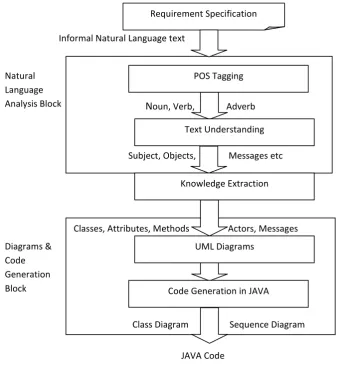
There are two basic modules of the system NL analysis and Diagram & code generation as shown in Fig 1. The requirement specification is the artifact given by the user
which describes the system using informal natural language. A part of Speech (POS) tagging [8] is the first phase of text processing. Each token is analyzed and classified into its respective POS classification: Noun, verb, pronoun, adverb, Helping-verb, adjective, prepositions, etc. In text understanding phase words are categorized into various further classes as subject part, object part, verb part, Message part, etc. This classification helps to find out classes and their respective methods and attributes.
[image:2.595.78.417.338.706.2]Knowledge extraction module, extracts different objects and classes and their respective attributes on the basses of the input provided by the preceding module. This module also finds out actors. Nouns are symbolized as classes, actors and their associated attributes are termed as attributes. Finally UML diagrams are generated by combining available symbols according to the information extracted of the previous module. As separate data is extracted for various diagrams as classes, sequence, so the separate functions are implemented for respective diagram. Last module generate code in the languages like Java, the generated code is structured according to the knowledge extracted in the previous modules and the UML diagrams generated.
Fig 1: System Block Diagram Diagrams &
Code Generation Block Natural Language Analysis Block
Classes, Attributes, Methods Actors, Messages
Class Diagram Sequence Diagram
N
oun, Verb, Adverb
Subject, Objects, Messages etc POS Tagging
Text Understanding
Knowledge Extraction
UML Diagrams
Code Generation in JAVA
JAVA Code Informal Natural Language text
3.2
Design Algorithm
Proposed system reduces the complexity by dividing application in smaller modules as follows:
Identifying stop words: Stop words (such as a, the, in, etc) are not useful to extract knowledge. Therefore such words are identified & stored in a list. These are not used for further analysis.
For e.g. “The library System is used by the Informatics students and Faculty”
In this sentence the, is, by, and these stop words are stored in a separate list Stopwords_found_List and are not used for further analysis. We have already stored most frequent stop words & with simple matching algorithm stop words from the given text can be identified.
Stemming: Stemming algorithm is used to find the stem (root) of each concept (CT) for further analysis. Once stop words are identified and removed, each inflected word is reduced back to its stem. We have used a Stemming technique that abbreviates word by removing affixes and suffixes.
POS tagger: It parse output to extract Proper Nouns (NN), Noun phases (NP), verbs (VB). And save it in Concepts list. We have used OpenNLP POS Tagger to perform Noun Analysis, & Verb Analysis.
For e.g. POS analysis of given input text.
“The library System is used by the Informatics students”
Is Parsed to:
The: Other library: noun System: noun is : verb used: verb by: adverb the: Other Informatics: noun students: noun
Lexical text Analysis: For each concept in Concepts-list synonyms and hyponyms are find out using Wordnet dictionary .These synonyms & hyponyms are stored in separate lists. If synonym list contains a concept (CT2) which have a synonym (SM) which lexically equal to CT, then CT and CT2 concepts are semantically related to each other. We have used WORDNET [7] online dictionary to find synonyms and hyponyms of the words.
For each concept (CT) in Concepts-list if hypernyms_list contains a concept (CT2) which have a hyponyms (HM) which lexically equal to CT, then CT2 “is a kind of” CT. Then result is saved as Generalization-list. Once the Generalization-List is available classes are refined with the help of User Knowledge. Different rules are applied on output of concept extraction to Identify Class, Attribute and Relationship among classes.
Class Identification Rules:
If a concept is occurred only one time in the document and its frequency is less than 2 %, then ignore as class.
If a concept is related to the design elements then ignore as class. Examples: “application, system, data, computer, etc…”
If a concept is related to Location name, People name, then ignore as a class. Examples: “Seeta, Ram,
If a concept is an attribute, then ignore as a class. Examples: “name, address, number”
If a concept is noun phrase (Noun+Noun), if the second noun is an attribute then the first Noun is a class. The second noun is an attribute of that class. Examples: “Student Name” or “Book ISBN”
If a concept is found in the high level of hyponyms tree, this indicates that the concept is general and can be replaced by a specific concept, then ignore as class. Examples: “user, object, etc.”
Attribute Identification Rules:
If a concept is noun phrase (Noun+Noun), then the second noun is an attribute.
We have predefined a list of popular attributes, if concept matches with predefined list it is an attribute.
Relationship Identification Rules:
If the concept is verb (VB), then by looking to its position in the document, if we can find a sentence having (CT1 - VB – CT2) where CT1 (concept 1) and CT2 (Concept 2) are classes, then (VB) is an Association relationship.
If the concept is verb (VB) and satisfies Rule1,and the concept is equal to one of the following {"consists of", "contain", "hold, "include", "divided to", "has part", "comprise", "carry", "involve", "imply", "embrace"}, then the relationship that discovered by that concept is Composition or Aggregation.
Given a sentence in the form CT1 + R1 + CT2 + “AND”+ CT3 where CT1, CT2, CT3 is a classes, and R1 is a relationship. Then the system will indicate that the relation R1 is between the classes (CT1, CT2) and between the classes (CT1, CT3)
Given a sentence in the form CT1 + R1 + CT2 + “AND NOT”+ CT3 where CT1, CT2, CT3 are classes, and R1 is a relationship. Then the system will indicate that the relation R1 is only between the classes (CT1, CT2) and not between the classes (CT1, CT3)
4.
RESULT
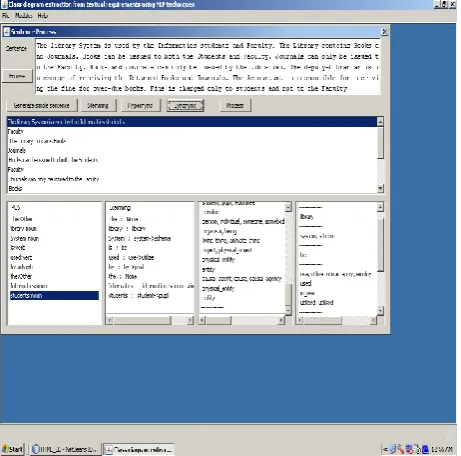
[image:4.595.54.285.207.435.2]Requirement specification is user expectations for a new or modified product. These features, called requirements, must be quantifiable, relevant and detailed. It is the informal description of the system. It can be anything like text file, a web page, word file or rich text document etc. User can define the system in English language & submit it as a text document. This requirement file is served as an input to the Concept Extraction phase. Fig. 2 shows the snapshot of our system in which one can see the Browse button using which user can browse the requirement specification file or user can type the specification in the given text box.
Fig. 2: Requirement Specification & Lexical Processing GUI
4.1
Lexical Pre-processing
The Lexical Preprocessor consists of four modules namely, a tokenizer, sentence splitter, POS tagger and Stemming. The input to the lexical preprocessor is a plain text file containing a description of the problem at hand (informal requirements). The output is a set of Synonym, Hyponym & tagged words, one per sentence, to be used by the Concept Extraction phase as shown in Fig. 2. The processing steps are carried out in the following order:
(a) Tokenization: The tokenizer splits a plain text file into tokens. This includes, e.g., separating words and punctuation, identifying numbers, and so on.
(b) Sentence Splitting: The sentence splitter identifies sentence boundaries.
(c) Part-of-Speech (POS) Tagging: Part-of-speech tagging is the process of assigning a part-of-speech like noun, verb, pronoun, preposition, adverb, adjective or other lexical class marker to each word in a sentence. The POS tagger assigns to each token in the input one of POS tags. We have used a slightly modified version of the Brill tagger [8].
(d) Stemming: After POS tagging, all nouns and verbs are passed to the Stemmer which returns the root and suffix of each word. For example, a plural noun like “students” will be analyzed as “student + s”, and an inflected verb form like “framing” will be analyzed as “frame + ing”. These roots and suffices are included in the input to the parser.
4.2
Concept Management
System includes an interactive user interface (UI) that manages the tasks such as creating, printing, saving and analyzing requirement. It also handles the graphical representation of the diagrams and let user add, delete, rename classes and relationships in the class diagram. As a part of UI, concept management UI is a very important interface which let user add, modify, view, and organize concepts and relationships. User can simply add new concept, change the concept type, and add new relationship. Our system gives user the flexibility to lead the processing in the way he/she wants. The diagram can be exported for some other application.
[image:4.595.312.548.311.504.2]Following Fig 3.shows the GUI (graphical User Interface) for Concept Management.
Fig 3: GUI for concept management
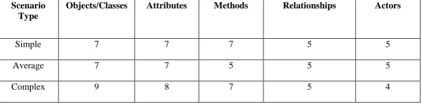
To test the accuracy of the diagrams generated by the designed system five parameters are used. Each generated diagram is tested under: no. of objects and classes, no. of attributes, no. of methods, no. of associations and no. of actors. A matrix of results of generated diagrams is shown below.
In the graph we have taken three different requirement specifications from different group of peoples. The results shown are for a library system. We have taken input text from students, who had specified the requirements in very simple language (Simple Scenario). Then the faculties gave more detail requirements (Average Scenario). The librarian gave the complete & complex requirements (Complex Scenario). Following result show the output comparison of the above
Table 1: Testing Result of UML diagrams
From result it is clear that, even if the specified requirements are simple, average or complex, the generated output will be almost same because of strong semantic support and rules which are used to build the system.
Graph 1: Testing Result of UML diagrams
0 2 4 6 8 10
Object/Classes Attributes Methods Relationship Actors
Simple
Average
Complex
5.
CONCLUSION AND FUTURE WORK
We propose an enhanced approach that is based on NLP techniques to support the extraction of, class diagram, sequence diagram & code template from NL requirements specification. We validate our approach by implementing a system called “NLP Based Object Oriented Analysis and Design from Requirement Specification”. System finds concepts based on nouns, Noun phrases and verbs analysis. It also finds relationships such as Generalization, Association and dependency. In sequence diagram system can find forward, reverse and self messages. The UML diagrams can be graphically represented and modified. The system is easy to use and diagrams can be generated semi automatically .The system expects user to be a domain expert. User who does not have much knowledge of UML modeling can also generate the diagrams. It is assumed that as System can generate class diagram from static model & Sequence diagram from Dynamic model of software engineering, same approach can be used to generate other UML diagrams also. The system can be evolved further by using learning algorithms. It can help in improving efficiency and accuracy of the diagrams.
6.
REFERENCES
[1] Imran Sarwar Bajwa, Ali Samad, Shahzad Mumtaz, 2009. Object Oriented Software Modeling Using NLP Based Knowledge Extraction. European Journal of Scientific Research ISSN 1450-216X Vol.35 , pp 22-33
[2] Mohd Ibrahim, Rodina Ahmad, 2010. Class diagram extraction from textual requirements using Natural language processing (NLP) techniques. In proceedings of the Second International Conference on Computer Research and Development.
[3] Xiaohua Zhou and Nan Zhou, 2004. Auto-generation of Class Diagram from Free-text Functional Specifications and Domain Ontology.
[4] Vinay S, Shridhar Aithal, Prashanth Desai, 2009. An Approach towards Automation of Requirements Analysis. In Proceedings of the International MultiConference of Engineers and Computer Scientists 2009 Vol I IMECS, Hong Kong,
[5] W.M.P. van der Aalst, 2002. Inheritance of Dynamic Behavior in UML. In Proceedings of the Second Workshop on Modelling of Objects, Components and Agents (MOCA 2002), Vol. 561 , pp. 105-120 Key: citeulike:679014 [6] Hector G Perez-Gonzalez, Jugal K. Kalita, 2002. GOOAL:
A Graphic Object Oriented Analysis Laboratory. OOPSLA, Seattle, Washington, USA.ACM 1-58113-626-9/02/0011. [7] WordNet (2.1)http://www.cogsci.princeton.eu/~wn/. [8] OpenNLP Tagger: http://www.textanalysis.com/Apps/
POS_Tagger/pos_tagger.html.
Scenario Type
Objects/Classes Attributes Methods Relationships Actors
Simple 7 7 7 5 5
Average 7 7 5 5 5