EFFECT OF CNT REINFORCEMENT ON THE FATIGUE BEHAVIOUR OF HIGH
STRENGTH STEEL S1100Q USING COMSOL MULTIPHYSICS.
Babalu Kumar
a, Abhi Bansal
b, Manash Dey
ca,c Assistant Professor, JIMS Enginnering Management Technical Campus, Greater Noida, 201306, India.
bAssistant Professor, Dronacharya college of Enginnering, Gurugram, 123506, India
---***--- ABSTRACT: This study shows the fatigue behavior of a high strength steel model acted by a fluctuating loading using FEA based software COMSOL Multiphysics. The low cycle fatigue behavior is predicted using strain based approach in COMSOL Multiphysics. Then the mechanical properties of CNT’s are determined. These CNT’s are then reinforced in Steel to enhance its properties. Effects of CNT reinforcement on the fatigue behavior of metal matrix composite predicted.Results shows that effects of CNT reinforcement in metal matrix on the fatigue behavior are significant.
Keywords- Strain based fatigue, Smith-Watson –Topper criterion, COMSOL Multiphysics.
Introduction:
The service life calculation of a cyclic loaded component is based on knowledge of the stresses or deformations in critical cross sections, usually calculated by means of the finite element analysis (FEA). The main parameters influencing the fatigue life are the external loads and the strength behaviour of the material. Therefore, the appropriate fatigue properties of the material should be known for such analysis.
Fatigue module in COMSOL
There are following four types of fatigue study present in COMSOL
1. Stress based
2. Strain based
3. Energy based
4. Cumulative damage based.
Strain-Based Fatigue Models
In the low-cycle fatigue analysis, the plastic strains in each cycle are more significant on macroscopic scale label. These strains must then be computed, which many times is the main challenge of the analysis. There are two basic methods to handle this: First one is Full elastoplastic analysis, and Second one is Elastic analysis with an approximation for the plasticity.These two methods are available for all type models via the Solution type parameter in the Fatigue Model Selection section of the option for plasticity approximation is only available with elastoplastic analysis.
The most simple method is to do a full elastoplastic analysis and feed the results into the fatigue evaluation. However, this
approach can be computationally expensive because the relevant strain input come from a stabilized cycle. With plasticity, due
to shake-down or ratcheting, for example, it might be so that several cycles must be computed before such a cycle is obtained. When it is found that the representative of fatigue cycle must calculated in a separate study and FEA to fatigue evaluation.
Elastic Analysis
SMITH-WATSON-TOPPER (SWT) MODEL
Smith-Watson-Topper (SWT) is a type of critical plane model where the plane normal to the maximum normal strain range, Δεn, is considered. The model is described by
The left-hand side is commonly called the SWT parameter and contains the maximum normal stress during the cycle on the
critical plane, σn,max. The right-hand side contains the reversals to failure, Nf, and material parameters , E, b, , and c. At low stresses and strains the fatigue life is limited by a Cycle Cutoff.
WANG-BROWN MODEL
The “Wang-Brown model” is based on the find out the plane with maximum change in shear strain, Δγ. It contains one another material parameter, S, which shows the sensitivity to the change in normal strain, Δεn, on the critical plane. But In reality, S is not a constant but it has some dependence on the level of load . It is usually of the order 1.0–2.4 for LCF, but it can be as low as 0.3 close to the fatigue limit. The model is described with
where the right-hand side contains the reversals to failure, Nf, and material parameters , E, b, , and c.
If the model is used in the HCF regime, it might be necessary to compensate for mean stress effects. This can be done using Morrow’s mean stress correction. The Basquin term of the equation is then modified so that
Here σ,mean is the mean normal stress on the maximum shear plane. It is computed as the average of the maximum and
minimum normal stress on the critical plane during the load cycle. At low strains the fatigue life is limited by a Cycle Cutoff.
FATEMI-SOCIE MODEL
The “Fatemi-Socie model” also depend on the same ideas as the Wang-Brown model and also considers a plane with the largest change in shear strain, Δγ Rather than the normal strain, it uses the maximum normal stress during the cycle on the critical plane, σn,max, to model in the influence of an opening of the micro crack. In its fundamental form the model is formulated using the fatigue properties for pure shear, something that could be obtained from a torsion test. The Fatemi-Socie relation can be written as
where the right-hand side contains the reversals to failure, Nf, and material parameters , G, b, , and c. The normal stress sensitivity constant, k, can be set to 1 as an initial approximation. In reality, k is not a constant but has some dependence on the load level. σys0 is the initial yield stress of the material. At low stresses and strains the fatigue life is limited by a Cycle Cutoff.
ELASTIC NOTCH APPROXIMATION
Neuber’s rule states that for a notch the product of elastically computed stress and strain is equal to the product of the actual, inelastic, stress and strain. Strictly speaking, it is defined only in terms of an uniaxial stress state. In practice, the stress states are often multiaxial, so here Neuber’s rule is expressed with equivalent stresses, σeq,and strains, εeq. (3-1)
In this equation the left-hand side has an “e” denoting the results of an elastic analysis, while the right-hand side contains the actual values.In strain-based fatigue analysis it is common to assume a Ramberg-Osgood material law when modeling the cyclic plastic behavior εeq(3-2).
where E is the modulus of elasticity. The parameters K’ and n’ are material constants of the cyclic response and not the
monotonic response obtained from a standard tensile test.
Initially, Equation 3-1 and Equation 3-2 are solved together to obtain the elasto-plastic equivalent (in a von Mises sense) stresses and strains. Hoffmann and Seeger (Ref. 1) have developed an algorithm for approximate computation of the stress and strain amplitudes in a multiaxial case. By following the Hencky's rule and utilizing the generalized notation of the Hooke's law they obtained following expression for the total elasto-plastic strains
where is the Poisson’s ratio, is the effective Poisson’s ratio and σ1 and σ2 are the principal stresses. The third principal stress is zero. The expression for the equivalent stress is given by
Their work shows that the ratio is almost constant in a notch and justifies the use of this assumption. From the equations above the solution to the first principal stress and strain is given by
Numerically, directions of the principal notch stresses are evaluated in following way. The direction of is taken as the
direction of the elastic principal stress that is largest in magnitude. The direction of is taken as the direction of the elastic
principal stress that is smallest in magnitude. The direction of is taken as the direction of the remaining principal elastic
stress.
Strain based approach is used in the reference paper and the material parameters are derived experimentally which I have used in my model.
PROBLEM STATEMENT
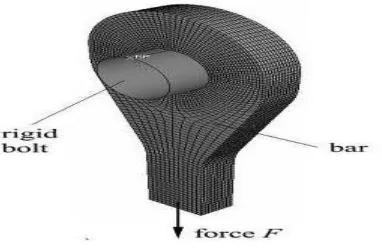
The fatigue properties of high strength steel are presented here. Computational analysis is performed using the local strain-life approach using COMSOL MULTIPHYSICS, where appropriate material properties for treated high strength steel are used. A counterweight weight bar made of high strength steel is acted by a fluctuating loading with maximum amplitude 880 and minimum amplitude of 88kN[11].
[image:4.612.191.382.418.542.2]Figure-1. Counter weight bar of Steel
In COMSOL for strain based fatigue study Smith-Watson –Topper criterion is used which is,
………. 3.1
where is the total strain amplitude, E is the modulus of elasticity, is the fatigue strength coefficient, b is the fatigue strength exponent, is the fatigue ductility coefficient and c is the fatigue ductility exponent.
The low-cycle fatigue parameters for high strength steel result in:
fatigue strength coefficient: = 2076 M Pa
fatigue strength exponent: b = −0.0997 fatigue ductility coefficient: = 9.93 Fatigue ductility exponent: c = −0.978
These are all material parameters which are obtained from plot of strain amplitude (ε) versus number of cycles(N).
STEPS –
1. Build the steel model in INVENTOR.
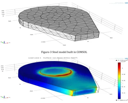
2. Then import it in COMSOL and Assign material to the model.
[image:5.612.82.529.360.722.2]E= 194889[MPa], Density=7800 kg/mm^3, Poission’s ratio=0.3 3. Then applied fixed constraint and boundary load as given in problem. 4. Compute study to obtain stress distribution.
For Fatigue study-
STEPS-
1. In add physic select fatigue study and then select strain based fatigue method.
2. Add another study to model.
3. Assign required fatigue model parameters in material-and compute study-2.
4. This gives the number of cycles to failure which is in good agreement of experimental results.
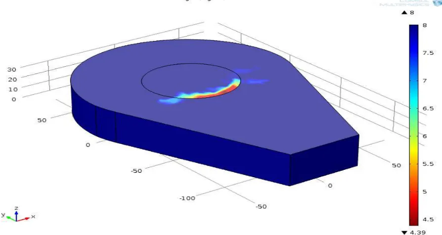
Figure-5 Number of cycles to failure for Steel model
[image:6.612.80.527.188.426.2]Results & Discussion:
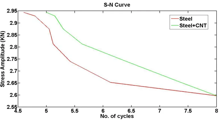
Figure-7 Comparison of S-N plot of (Steel) and (Steel reinforced with CNT) model
Figure 5 shows the number of cycles to failure for Steel model acted by the fluctuating loading shown in figure 2. The number of cycles to failure when the Steel model which is 24547 cycles.Figure-6 shows the S-N curve of Steel model. So by reinforcing the CNT the number of cycles to failure increases. But as the number of cycle increase from low to high value (i.e.≥ 10^4) this effect is not very significant.
Conclusion-
For low cycle fatigue study the number of cycles to failure obtained by COMSOL Multiphysics are in very good agreement with experimental results. In this study CNT is used as reinforcement in Steel model to predict its fatigue behaviour..Here same geometrical model for both Steel and Steel reinforced with CNT’s are used under identical boundary condition and loading condition to predict their fatigue behaviour.It was observed that the number of cycles for fatigue failure in case of CNT reinforced steel is increased in comparison to the number of cycles for fatigue failure in steel model.
REFERENCES-
1. Glodež, S.; Knez, M. & Kramberger, J Fatigue behavior of High Strenght Steel S1100Q Advance Engineering 1st Year
(2007) – Volume 2
2. Stephens R.I.; Fatemi A.; Stephens R.R. & Fuchs H.O. (2001). Metal Fatigue in Engineering, John Wiley & Sons Inc, New York.
3. Zahavi E.; Torbilo V. (1996). Fatigue Design, CRC Press, New York.
4. ASTM E 606 (1998). Standard Practice for Strain-Controlled Fatigue Testing, ASTM
standard.
5. Ralph I. Stephens, Ali Fatemi, Robert R. Stephens, Henry O. Fuchs, Metal Fatigue in Engineering, Wiley publication.
6. Aurtur K. Kaw, Mechanics of Composite materials, CRC publication.
7. Schijve J. Fatigue Struct Mater 2009.
8. Zhang Z, Chen DL. Scr Mater 2006;54:1321.
10. Y.J. Liu, X.L. Chen Evaluations of the effective material properties of carbon
nanotube-based composites using a nanoscale representative volume element Mechanics of Materials 35 (2003) 69– 81
11. Daniel C. Davis a, Justin W. Wilkerson , Jiang Zhu , Viktor G. Hadjiev, A strategy for improving mechanical properties of
a fiber reinforced epoxy composite using functionalized 71 carbon nanotubes, Composites Science and Technology (2011) 1089–1097
12. Yi-Ming Jen , Yung-Chuan Wang, Stress concentration effect on the fatigue properties of carbon nanotube/epoxy composites, Composites: Part B 43 (2012) 1687–1694
13. Yi-Ming Jen, Yu-Hsiang Yang, A study of two-stage cumulative fatigue behavior for CNT/epoxy.
14. Glozed, S.; Knez, M. & Kramberger, J.Fatigue behaviour of high strength steel.
15. M.M. Sharma, C.W. Ziemian, T.J. Eden, Mater. Des. 32 (2002) 4304–4309.
16. N. Chawla, U. Habel, Y. LShen, C. Andres, J.W. Jones, J.E. Allison, Metall. Mater. Trans. A 31 (2000) 57–70.