Global-Local Contrast Enhancement
S. Somorjeet Singh
Department of Computer Science Manipur University, Canchipur
N. Gourakishwar Singh
Department of Computer Science Manipur University, Canchipur
Th. Tangkeshwar Singh
Department of Computer Science Manipur University, Canchipur
H. Mamata Devi
Department of Computer Science Manipur University, Canchipur
ABSTRACT
Using global contrast enhancement, low contrast image can be improved in its quality globally. The enhanced output image, with such type of enhancement, may not have the noise and ringing artifacts. However, it may have over-exposure on some parts of the image and under-exposure on some other parts of the image when too high contrast gain occurs. Besides these, the enhanced output image may lack of local details. On the other hand, using local contrast enhancement, the local details of an image can be better defined. However, local contrast enhancement may produce the output image with noise and ringing artifact when too much contrast gain occurs. Besides these, it may be poor in global contrast. For some images, applying the local contrast enhancement along with global contrast enhancement is much better than that of global contrast enhancement only or local contrast enhancement only.
Keywords
Global- Local, Contrast.
1.
INTRODUCTION
Contrast factor is one of the factors of low or good quality images. An image cannot be said to be of good quality when it has very low contrast or too high contrast. However, the quality of low contrast images can be improved by using global contrast enhancement or local contrast enhancement. Low contrast image can be improved in its quality globally by using global contrast enhancement and the information are more defined globally as compared to the original image. And the quality of low contrast image can be improved regionally by using local contrast enhancement and the local details are shown more distinctly as compared to the original image.
Global enhancement methods [1]-[6] are generally fast in the processing speed of the enhancement as compared to the local contrast enhancement. However, the processed output images produced by global contrast enhancement methods generally lack of local details. Some of the most frequently used methods are linear contrast stretching, histogram equalization etc. When an image is poor in global contrast only, only the global contrast enhancement methods are sufficient to improve the quality. However, such a situation does not always occur. In most of the images, the image characteristics differ considerably from one region to another in the same image. This is one of the main causes of the need of local contrast enhancement for such type of images and the local details are defined only when the local contrast enhancement is applied.
Several local contrast enhancement methods are utilized in different images in the different fields, like medical images, real-time images, surveillance applications and many others.
Dorst [7] used an adaptation technique of histogram stretching method over a neighbourhood around the candidate pixel for local contrast stretching. Then, several enhancement techniques [8]-[11] of histogram equalization based on adapting the same over a sub-region of the image had been reported. Lee [12],[13] suggested a local contrast stretching method in which local statistics of a predefined neighbourhood are used in modifying the gray level of a pixel. The method designed by Narendra and Fitch [14] used the amplification factor too to be a function of the pixel based on the local gray level statistics over the same neighbourhood in which contrast gain is inversely proportional to Local Standard Deviation (LSD). From the observation of Dah-Chung [15], image enhancement with contrast gain is constant or inversely proportional to the LSD produces either ringing artifacts or noise over enhancement due to the use of too large contrast gains in regions with high and low activities and developed a new method in which gain is a non-linear function of LSD. Another method was introduced by Schutte [16] that a multi-window extension of the technique using LSD was utilized and how the window sizes should be chosen was shown. Sascha [17] implemented an improved multi-window real-time high frequency enhancement scheme based on LSD in which gain is a non-linear function of the detail energy. Some of the enhancement-methods which are using LSD’s suffer from divide by zero condition when LSD’s of some pixels are having the value zero. This divide by zero can be overcome [18] by modifying the LSD’s, changing with a very small negligible value.
Low contrast images are of different types. Some images are poor in global contrast only and some are poor in local contrast only. However, for some images, besides local contrast, global contrast is also poor. For such types of images, only the global contrast enhancement or local contrast enhancement is not sufficient and to get the better enhanced output image, there is a room for both of the applications i.e. global contrast enhancement as well as local contrast enhancement.
This paper is organized as follows: Section 2 briefly reviews some enhancement methods. Section 3 describes our proposed method of the application of both of global contrast enhancement and local contrast enhancement. Section 4 shows experimental results and discussion. And Section 5 is for conclusion.
2.
REVIEW ON SOME METHODS
0 0
(
1)
( )
(
1)
( )
k k
k k r j j
j j
L
S
T r
L
p r
n
MN
(1)where k=0,1,2,…,L-1, rk is a pixel in the input image, Sk is the
corresponding pixel in the output image, pr(rj) is the
Probability Density Function of rj, MN is the total number of
pixels in the image and nj is the number of pixels that have
intensity rj.
For the contrast enhancement of an image, most of the people usually try it with GHE. Although GHE is one of the most frequently used enhancement methods, it is not always desirable [19], because either over enhancement in some parts of the output image or under exposure in some another parts of the same output image is occurred. In another sense, some information may be lost in the output image. Another limitation of GHE is that there is no user’s option to control the enhancement level to employ this method.
Next is also one of the global contrast enhancement methods. The contrast gain in this method is controlled with single user defined parameter and the method is semi-automatic in nature. This method, i.e. semi-automatic global contrast enhancement (SAGCE) [6] can be expressed as
(1
) (
) 0.5
o g i meanf
C
f
g
(2)where, fo is the output pixel value, fi is the input pixel value,
Cgis the global contrast gain factor, gmean is the global mean
of the pixel values of the image and the threshold too. With this method, global mean of the pixel values of the original image is always brought into the value 0.5 automatically in the output image and the contrast gain can be controlled by using only Cg. This method is user friendly so
that when Cg is increased, the gain in the global contrast is
increased, when Cg is more increased, the output image will
have more gain in the global contrast and the upper and lower range of intensity are adjusted uniformly with the reference of gmean. This method is very convenient to the user to
combine with other local contrast enhancement methods because this method has very less number of user defined parameters i.e. single user defined parameter.
Next is one of the local contrast enhancement methods using LSD in which divide by zero condition can be overcome [18]. In this method, the enhanced output image can be described as
( , )
( , )
( , )
( , )
( , )
C
f i j
x i j
x i j
m i j
i j
s
(3)where, x(i,j) is the gray scale value of a pixel in an image,
f(i,j) is the enhanced value of x(i,j), m(i,j) is the local mean, (i,j) is the LSD, C is for local contrast control, and s is a very small and negligible quantity greater than zero.
The removal of divide by zero, with this method, doesn’t affect the quality of the enhancement. It retains the same local contrast enhancement quality except the removal of divide by zero condition.
3.
GLOBAL-LOCAL CONTRAST
ENHANCEMENT (GLCE)
Either global contrast enhancement method or local contrast enhancement method is limited to those images which are poor in global contrast as well as in local contrast. For such images, there is the need of a method in which both the global
[image:2.595.317.519.105.482.2]contrast enhancement and the local contrast enhancement are applied.
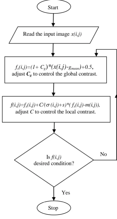
Fig. 1. Flowchart for GLCE
The Global-Local Contrast Enhancement (GLCE) method is a method in which both the global contrast enhancement and the local contrast enhancement are applied. Using equation (2) and equation (3), GLCE method can be implemented as follows.
Using equation (2),
( , )
(1
) [ ( , )
] 0.5
x g mean
f i j
C
x i j
g
(4)where, x(i,j) is the pixel value at location (i,j) of the original input image, Cgis the global contrast gain control, gmean is the
global mean of the pixel values of the whole image and the threshold too and fx(i,j) is the enhanced value of the pixel
x(i,j).
Then applying equation (3) on the output values given by equation (4) as,
( , )
( , )
( , )
( , )
( , )
x x
C
f i j
f i j
f i j
m i j
i j
s
(5)where, fx(i,j) is the globally enhanced output value of the
original pixel value x(i,j) at location (i,j) of the original input Start
Read the input image x(i,j)
fx(i,j)=(1+ Cg
)
*(x(i,j)-
gmean)
+0.5,
adjust Cg to control the global contrast.
f(i,j)=fx(i,j)+C/(
(i,j)+s)*( fx(i,j)-m(i,j)),adjust C to control the local contrast.
Is f(i,j)
desired condition?
Stop
No
image using equation (4), m(i,j) is the local mean at (i,j)
among the neighbourhood values of fx(i,j),(i,j) is the LSD at
(i,j) among the neighbourhood values of fx(i,j), C is the local
contrast gain control, s is very small and negligible quantity greater than zero and f(i,j) is the enhanced output value produced by GLCE.
Here, GLCE is controlled with the two user defined parameters at different stages. In the first stage, Cg controls
the global contrast so that the increase in Cg gives more global
contrast in the output. And in the second stage, C controls the local contrast in such a manner that the increase in C enhances the input image with more local contrast. However, the contrast controls of Cg and C should be done with certain
combinations of the values of Cg and C because when the
values of Cg and C are increased too large, some information
may be lost or may not be defined properly in the output image. For the input images with poor global as well as local contrast, with certain combinations of Cg and C, this method
i.e. GLCE will give a better output than either SAGCE only or method of equation (3) only.
(a) (b)
[image:3.595.312.548.238.499.2](c) Histogram of (a) (d) Histogram of (b)
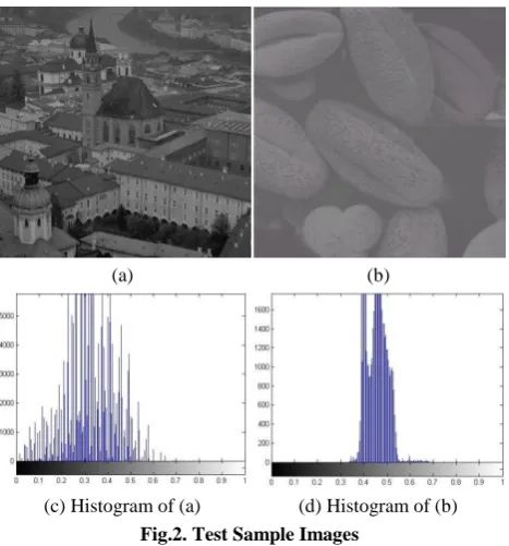
Fig.2. Test Sample Images
The whole procedure for implementing the above GLCE can be summarized as
1. Read the input image
2. Apply SAGCE to the input image as in equation (4) and adjust Cg to control global contrast.
3. Apply the equation (5) to the output from step 2 and adjust C to control local contrast to get the final output.
4. Check the output from step 3. If it is not the desired condition, take the input image again and repeat from step 2.
5. Get the final output image.
The flowchart of the GLCE is shown in fig. 1.
4.
EXPERIMENTAL RESULTS AND
DISCUSSION
Our proposed method has been tested on various test images using MATLAB 7.13.0.564 and the results compared with Global Histogram equalization (GHE), SAGCE and the method of equation (3).
Fig.2 shows two sample images and their histograms. Fig. 2(a) and Fig. 2(b) are two sample images with having different low contrast values and Fig. 2(c) and Fig. 2(d) are the corresponding histograms respectively. The image in Fig. 2(b) is having very low contrast values that it has very narrow range of intensity values in the histogram of the image as shown in Fig. 2(d) and the image is poor in global contrast as well as in local contrast.
(a) GHE (b) Method of SAGCE
(c) Method of Equation (3) (d) GLCE (proposed method)
Fig.3. Enhancement of fig. 2(a) with different methods
The enhanced output images of fig. 2(a), processed with different methods are shown in fig. 3. The image in fig. 3(a) is the enhanced output image processed with GHE. Fig. 3(b) is the enhanced output image processed with SAGCE with
Cg=0.8. Fig. 3(c) is the enhanced output image processed with
equation (3) with C=0.12. Fig. 3(d) is the enhanced output image processed with our proposed method i.e. GLCE with
Cg=0.08 and C=0.1. Here, the qualities of all of the output
images are improved from the original image. However, the information in the walls of the buildings are not defined properly due to the over enhancement with GHE and some portions are under exposure. And the output image enhanced with SAGCE is still poor in local contrast. And for the output image enhanced with the method of equation (3), it is still poor in exposure. And the output image enhanced with our proposed method, GLCE, is more improved in global contrast as well as local contrast, and objects are better defined.
[image:3.595.52.286.291.542.2](a) GHE (b) SAGCE
[image:4.595.50.288.68.576.2](c) Equation (3) (d) GLCE (proposed method)
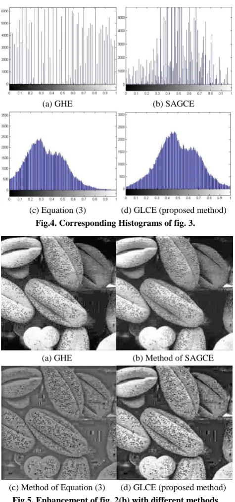
Fig.4. Corresponding Histograms of fig. 3.
(a) GHE (b) Method of SAGCE
[image:4.595.51.288.73.291.2](c) Method of Equation (3) (d) GLCE (proposed method)
Fig.5. Enhancement of fig. 2(b) with different methods
Again, the enhanced output images of fig. 2(b), processed with different methods are shown in fig. 5. The image in fig. 5(a) is the enhanced output image processed with GHE. Fig. 5(b) is the enhanced output image processed with SAGCE with Cg=5.5. Fig. 5(c) is the enhanced output image processed
with equation (3) with C=0.1. Fig. 5(d) is the enhanced output image processed with our proposed method i.e. GLCE with
Cg=4.0 and C=0.08. Here, the qualities of all of the output
images are much improved from the original image. However, the output image enhanced with GHE or SAGCE is still poor in local contrast. And for the output image enhanced with the method of equation (3), it is still very poor in global contrast. And the output image enhanced with our proposed method, GLCE, is more improved in global contrast as well as local contrast, and objects are better defined in this image again.
The corresponding histograms of the images of fig. 5 are
(a) GHE (b) SAGCE
[image:4.595.312.547.74.286.2](c) Equation (3) (d) GLCE (proposed method)
Fig.6. Corresponding Histograms of fig. 5. Table 1. Comparative Statements of Our Proposed
Method with Other Methods
GHE
Method of SAGCE et al., [6]
Method of Equation (3) et
al., [18]
GLCE (proposed
method)
Automatic and global enhancement
Semi-automatic and
global enhancement
Local adaptation of enhancement
Both global and local enhancement No user
defined parameter
control
Single user defined parameter
control
Single user defined parameter
control
Two user defined parameters
control It improves the
quality with global contrast,
however, it is poor in local
contrast
It improves the quality with
global contrast, however, it is
poor in local contrast
It improves the quality with local contrast,
however, it is poor in global
contrast
It improves the quality with global contrast as well as local
contrast
Enhancement unchangeable
Enhancement adjustable with single
parameter
Enhancement adjustable with
single parameter
Enhancement adjustable
with two parameters Most user
friendly User friendly User friendly
Slightly complicated By the observations of the enhanced output images, it is found that the output images produced by GHE and SAGCE reasonably improved the global contrast, however, there is still necessity for local contrast. In these output images, local details are not defined properly. And the enhanced output images produced by the method of equation (3) improved the local contrast reasonably, however, there is still need for the global contrast. Lastly, the enhanced output images produced by our proposed method (i.e. GLCE) improved the quality in global contrast as well as in local contrast. For a very low contrast image which is poor in both of global contrast and local contrast like the image shown in fig. 2(b), our proposed method, GLCE is much better than GHE, SAGCE or method of equation (3).
[image:4.595.308.549.330.585.2]5.
CONCLUSION
Global contrast enhancement methods improve the quality of a low contrast image with global contrast only. On the other hand, local contrast enhancement methods improve the quality of a low contrast image with local contrast only. However, for a very low contrast image which is poor in both of global contrast and local contrast, neither global contrast enhancement method only nor local contrast enhancement method only is sufficient. This paper proposes a new contrast enhancement method in which a combination of a global contrast enhancement method and a local contrast enhancement method is employed for such type of image. The proposed method is getting much better improvement from the global contrast enhancement method only and also from the local contrast enhancement method only. If either of the global contrast enhancement method or the local contrast enhancement method is changed, it may affect the quality of the global-local contrast enhancement. And the approach based on a better combination of the global contrast enhancement method and the local contrast enhancement method is the subject of future interest.
6.
REFERENCES
[1] S. Somorjeet Singh, H. Mamata Devi, Th.Tangkeshwar Singh, O. Imocha Singh, “A New Easy Method of Enhancement of Low Contrast Image Using Spatial Domain,” International Journal of Computer Applications (0975 – 8887), February 2012, Volume 40– No.1.
[2] R. C. Gonzalez and R. E. Woods, 2008, Digital Image Processing, 3rd edition, Prentice Hall.
[3] Sascha D. Cvetkovic and Peter H. N. de With, "Image enhancement circuit using non-linear processing curve and constrained histogram range equalization," Proc. of SPIE-IS&T Electronic Imaging, 2004, Vol. 5308, pp. 1106-1116.
[4] M.A. Yousuf, M.R.H. Rakib, “An Effective Image Contrast Enhancement Method Using Global Histogram Equalization,” Journal of Scientific Research, 2011, Vol. 3, No. 1.
[5] I. Altas, J. Louis, and J. Belward, “A variational approach to the radiometric enhancement of digital imagery,” IEEE Trans. Image Processing, June 1995, vol. 4, pp. 845–849.
[6] S. Somorjeet Singh, “Semi-Automatic Global Contrast Enhancement,” International Journal of Computer Applications (0975 – 8887), August 2012, Volume 51– No. 8.
[7] L. Dorst, “A local contrast enhancement filter,” In Proc. 6th Int. Conference on Pattern recognition, 1982, pages 604-606, Munich, Germany.
[8] Hyunsup Yoon, Youngjoon Han, and Hernsoo Hahn, “Image Contrast Enhancement based Sub-histogram Equalization Technique without Over-equalization Noise,” International Journal of Electrical and Electronics Engineering, 2009, 3:6, 323-329.
[9] D. Mukherjee and B. N. Chatterji, “Adaptive neighborhood extended contrast enhancement and its modification,” Graphical Models and Image Processing, 1995, 57:254-265.
[10] R. B. Paranjape, W. M. Morrow, and R. M. Rangayyan, “Adaptive-neighborhood histogram equalization for image enhancement,” Graphical Models and Image Processing, 1992, 54:259-267.
[11] S. M. Pizer, E. P. Amburn, J. D. Austin, R. Cromartie, A. Geselowitz, T. Geer, B. H. Romeny, J. B. Zimmerman, and K. Zuiderveld, “Adaptive histogram modification and its variation,” Computer Vision, Graphics and Image Processing, 1987, 39:355-368.
[12] J. S. Lee, “Digital image enhancement and noise filtering by use of local statistics,” IEEE Trans. on Pattern Analysis and Machine Intelligence, 1980, PAMI-2:165-. [13] J. S. Lee, “Refined filtering of image noise using local
statistics,” Computer Graphics and Image Processing, 1981, 15:380-.
[14] P.M. Narendra and R.C. Fitch, "Real-time adaptive contrast enhancement," IEEE Trans. PAMI, Vol.3, no. 6, pp.655-661, 1981.
[15] D.-C. Chang and W.-R. Wu, "Image contrast enhancement based on a histogram transformation of local standard deviation," IEEE Trans. MI, Aug. 1998, vol. 17, no. 4, pp. 518-531.
[16] K. Schutte, "Multi-Scale Adaptive Gain Control of IR Images," Infrared Technology and Applications XXIII, Proceedings of SPIE, 1997, Vol. 3061, pp.906-914.
[17] Sascha D. Cvetkovic, Johan Schirris and Peter H. N. de With, "Locally-Adaptive Image Contrast Enhancement Without Noise And Ringing Artifacts,” IEEE, ICIP 2007.
[18] S. Somorjeet Singh, Th.Tangkeshwar Singh, H. Mamata Devi, Tejmani Sinam, “Local Contrast Enhancement Using Local Standard Deviation,” International Journal of Computer Applications (0975-888), June 2012, Volume 47– No.15.