ISSN Online: 1942-0749 ISSN Print: 1942-0730
Analysis on Double Loop Wireless Power
Transfer
Jeffrey Wu
Shanghai High School International Division, Shanghai, China
Abstract
This paper examines the properties of the double loop wireless power mitter using numerical simulations. The double loop wireless power trans-mitter consists of two coupling and parallel loop antennas which transmit field energy through resonant electromagnetic waves. This technology can be applied in RFIDs (Radio Frequency Identification) and remote charging sce-narios where wires cannot be applied to, including the wireless charging of drones and satellites.
Keywords
Wireless Power Transfer, Antenna, Radio Frequency
1. Introduction
The wireless power transfer technology, also known as wireless energy transmis-sion technology, was first discovered and patented by Nikola Tesla [1]. Up till today, it remains a hot topic being discussed frequently in research fields.
Before the discovery of such technology, power has always been transferred by magnetic fields using the inductive coupling between coils of wire, or by electric fields using the capacitive coupling between metal electrodes [2]. However, these methods require transmitters and receivers to be in proximity, causing limits on possible applications of the technology.
Differing from the method mentioned above antennas, devices that can transform oscillating electric currents into traveling electromagnetic waves that move in specific direction or vice versa [3], can function as either transmitter’s receivers. Nowadays, antennas are generally applied for in technologies serving communicative purposes including the production of phones, radios, planes, and even solar power satellites [4][5][6][7].
This paper studies numerical facts of the double loop wireless power transfer How to cite this paper: Wu, J. (2017)
Analysis on Double Loop Wireless Power Transfer. Journal of Electromagnetic Anal-ysis and Applications, 9, 91-96.
https://doi.org/10.4236/jemaa.2017.96008
Received: May 9, 2017 Accepted: June 27, 2017 Published: June 30, 2017
Copyright © 2017 by author and Scientific Research Publishing Inc. This work is licensed under the Creative Commons Attribution International License (CC BY 4.0).
device, which consists of two resonant loop antennas. One of the antennas in this model shall be used for sending electromagnetic waves and the other one is used for receiving these waves. It is expected that this double loop wireless pow-er transmittpow-er could be applied to the technology of wireless transfpow-er of powpow-er, which enables the charging of devices located at a greater distance, incurring lower energy loss.
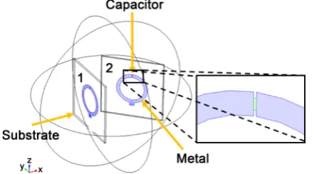
Figure 1 is the schematic illustration of the double loop wireless power trans-fer device, which consists of two loop antennas labeled as 1 and 2. Each antenna contains a metal loop (colored in blue), a capacitor and a substrate with relative permittivity of 10. The second antenna has been rotated 45 degrees with respect to the first antenna. The circles outside of the device indicate a 3D simulation region. The black box on the right side indicates the area at which the lumped capacitor (green part) is located.
2. Theoretical Background
The well-known coupled-mode equations (CMEs) are applied here as an appro-priate analytical framework for modeling this resonant coupling of energy transfer [8]:
(
)
(
)
1 1 1 1 2
2 2 2 2 1
d d
d d
a t i i a iKa a t i i a iKa
ω ω
= − − Γ +
= − − Γ +
where a1 and a2 are the individual amplitudes of each antenna,
ω
1 and ω2are individual Eigen-frequencies, Γ1 and Γ2 are the individual resonance
widths that result from the antennas’ intrinsic losses (such as absorption and radiation), and K is the coupling coefficient. In this approximation, the electric field of the coupled system can be approximated as E(r, t) = a1(t)·E1(r) + a2(t)·E2(r), where E2(r) and E2(r) are the Eigen-modes of the corresponding antenna. In this paper, the two antennas are identical, meaning ω ω1= 2 and Γ1=Γ2.
3. Model Definition
In order to achieve wireless power transfer with low energy loss, we shall assume that the metal loops utilized here are perfect electric conductors (PECs). It is ex-pected that PECs incur low losses within microwave frequency range. The radius of the loop wire is 2 cm and the radius of the loop is 20 cm. The metal loop
forms an inductor of 515 nH. In the capacitor, a dielectric material with a rela-tive permittivity of 10, radius of 5.4 cm, and thickness of 4 mm is inserted, the insertion shall yield a capacitance of 203 pF. To further simplify the simulation, the capacitance is modeled as a lumped element. The wires and capacitors are bonded with two square substrates, with dimensions 80 cm × 80 cm. Further-more, perfectly matched layers (PMLs) and scattering boundary conditions (SBCs) are applied as placed at the most outer side of the simulation domain, in order to avoid any unwanted back scattering.
4. Results and Discussions
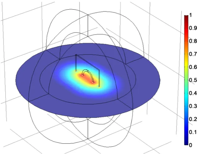
To get the value of ω in the CMEs, we first calculate the Eigen-frequency of the individual antenna. Resulting figures indicate that the field of the Eigen-mode is mostly concentrated around the loop, with the highest field remaining within the loop (see Figure 2 for details). The value of Eigen-frequency ω is 2π × 13.35 MHz. The imaginary part of the Eigen-frequency (484 Hz) gives resonance width (Г), indicating the loss of energy.
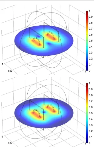
[image:3.595.214.535.457.705.2]The simulation on double loop structures is then performed. Due to the exis-tence of the coupled system, the previously individual Eigen-frequency is spitted into two Eigen-frequencies, with one’s value higher than the former unsplit Ei-gen-frequency and the other lower than the former. The electric field distribu-tion is shown in Figure 3. The top part illustrates the first mode at Eigen-fre- quency ω equals 2π × 13.27 MHz and the bottom at 2π × 13.41 MHz for second mode. Note that there is a node at the center of the illustration, located be-tween the two antennas, under the second mode, which is caused by required orthogonality. According to the CMEs, the Eigen-modes of the coupled system
Figure 3. Electric field distribution of the Eigen-modes of the double loop antenna with Eigen-frequency of 13.27 MHz (top) and 13.41 MHz (bottom). The figures are plotted in log-scale for easy visualization.
are split by 2K, which can be calculated from the two Eigen-frequencies. The energy exchange between the two antennas takes place at a time period of π/2K. Given that the coupling rate is much faster than all loss rates (K Г), it is ob-vious that our simulation resulted in success.
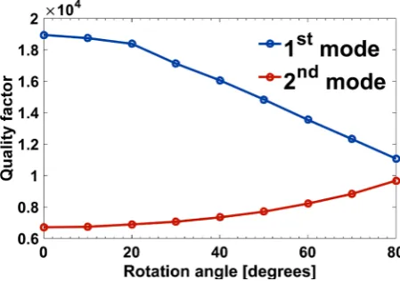
Figure 4. Quality factor as a function of rotation angle for the first and second mode.
mode decreasing while that for the second mode increases as the rotation angle increases. This clearly indicates that the coupling rates between the two antennas are decreasing quickly when the coupling coefficient is calculated from K.
5. Conclusion
In conclusion, this paper designs a scheme utilizing double loop antennas which can be applied in wireless power transfer. We can conclude from the simulations that after the testing of these simulations, it can be concluded that the double loop wireless power transfer using the resonances of tow antennas is reliable and efficient. It can be further concluded that when the angle between the two loops increases, the coupling rate will drop, resulting in the deterioration of the wire-less transfer performance. With further development, this technology can be improved to fit in many technological applications that are commonly used in our daily lives.
References
[1] Tesla, N. (1914) Apparatus for Transmitting Electrical Energy. US Patent No. 1119732.
[2] Tomar, A. and Gupta, S. (2012) Wireless Power Transmission: Applications and Components. International Journal of Engineering, 1, 5.
[3] Pozar, D.M. (2012) Microwave Engineering. 4th Edition, John Wiley & Sons, Inc., Hoboken.
[4] Karacolak, T., Hood, A.Z. and Topsakal, E. (2008) Design of a Dual-Band Implant-able Antenna and Development of Skin Mimicking Gels for continuous Glucose Monitoring. IEEE Transactions on Microwave Theory and Techniques, 56, 1001.
https://doi.org/10.1109/TMTT.2008.919373
[5] Mitchell, B.H. (2000) Protective Covering for a Cell Phone or a Pager. US Patent No. 6082535.
[6] Pozar, D.M. and Duffy, S.M. (1997) A Dual-Band Circularly Polarized Aper-ture-Coupled Stacked Microstrip Antenna for Global Positioning Satellite. IEEE Transactions on Antennas and Propagation, 45, 1618.
https://doi.org/10.1109/8.650073
Antenna for 12 GHz Satellite TV Reception. IEEE Transactions on Antennas and Propagation, 33, 1347-1353. https://doi.org/10.1109/TAP.1985.1143526
[8] Akbar, P.R., Saito, H., Zhang, M., Hirokawa, J. and Ando, M. (2016) Parallel-Plate Slot Array Antenna for Deployable SAR Antenna Onboard Small Satellite. IEEE Transactions on Antennas and Propagation, 64, 1661.
https://doi.org/10.1109/TAP.2016.2536164
Submit or recommend next manuscript to SCIRP and we will provide best service for you:
Accepting pre-submission inquiries through Email, Facebook, LinkedIn, Twitter, etc. A wide selection of journals (inclusive of 9 subjects, more than 200 journals)
Providing 24-hour high-quality service User-friendly online submission system Fair and swift peer-review system
Efficient typesetting and proofreading procedure
Display of the result of downloads and visits, as well as the number of cited articles Maximum dissemination of your research work