Modeling of SVC Controller based on Adaptive PID
Controller using Neural Networks
Afaneen A. Abood
Electrical Engineering Department, College ofEngineering Technology University
Baghdad, Iraq
Firas M. Tuaimah
Electrical Engineering Department, College ofEngineering Baghdad University
Baghdad, Iraq
Aseel H. Maktoof
Electrical Engineering Department, College ofEngineering Baghdad University
Baghdad, Iraq
ABSTRACT
The Flexible AC Transmission System (FACTS) technology is a promising technology to achieve complete deregulation of power system based on power electronic devices, used to enhance the existing transmission capabilities in order to make the system flexible and independent in operation then the system will be kept within limits without affecting the stability. Complete closed-loop smooth control of voltage can be achieved using shunt connected FACTS devices.
Static VAR Compensator (SVC) is one of the shunt connected devices, which can be utilized for the purpose of voltage and reactive power control in power systems. In this paper the considered structure of SVC consists of (TCR-FC) which is applied at SMIB system model, the dynamic equations for the (SMIB-SVC) model will be presented, the system equations expressed in terms of state space equations then by using MATLAB the plant of the system model will be presented under various loading conditions.
A Neuro-PID controller model has been developed to improve on the response and performance of a conventional Proportional plus Integral plus Derivative (PID) controller which control the response of the plant model by developing a self-tuning/adaptive Neural-PID controller. The proposed Neuro-controller was developed using the back propagation algorithm. The ANN based PID (ANN-PID) controller compared with ANN controller through MATLAB simulation results. Comparison of performance responses of ANN controller and ANN-PID controller show that ANN-PID controller has quite satisfactory generalization capability, feasibility and reliability, as well as the accuracy in the system; the superiority of the performance of ANN over PID controller is highlighted under various loading conditions.
Keywords
SVC controller, power systems, neural network, back propagation algorithm, PID controller, self-tuning.
1. INTRODUCTION
Relieving the power system from the effects of heavy losses and higher voltage magnitude deviations is very important to improve voltage profile at the load bus [1].
Static var compensator (SVC) is one of the FACTS technologies that are used widely for power transmission systems applications, many countries have continuously equipped SVCs in the past years and have obtained considerable profit [2,3]. SVC is an important reactive compensation device that has been used in power systems to maintain bus voltage at a constant level, improve the transient stability, dampen the systems and suppress voltage flicker since it provides an excellent source of rapidly controllable reactive shunt compensation for dynamic voltage control through its utilization of high-speed thyristor switching/controlled reactive devices. In this paper the SVC is a shunt connected static generators / absorbers whose outputs are vary so as to control voltage of the electric power systems. In its simple form, SVC is connected as Fixed Capacitor-Thyristor Controlled Reactor (FC-TCR) configuration. The TCR provides a “smooth” or continuously control to maintain the desired voltage at a high voltage bus. If the voltage bus begins fall below its set point range, the SVC will inject reactive power into the system (within its control limits), thereby increasing the bus voltage back to its desired voltage level. If bus voltage increase, the SVC will inject less (or TCR absorb more) reactive power (within its control limits), and the result will be to achieve the desired bus voltage [4].
In fact, to dynamically support the voltage in power system and enhance SVC capability, the design of SVC controllers has attracted much attention from scholars and engineers [5, 6]. Many different types of controlling schemes have been investigated and applied to SVC such as conventional PID [7], linear optimal [8], adaptive control methods [9, 10].
This paper is focused on using an adaptive intelligent self- tuning controlling system in order to enhance the response of SVC with power system under different changing. In order that an intelligent tuner can be capable of enhancing the system performance response, a special control algorithm with features of easy implantation like how computational requirements, adaptive, simple, reliable and so on.
combination between ANN and PID controller has been proposed. Nevertheless, PID controller is simple and when combined with ANN most of its disadvantages have been solved through the using of self-tuning characteristic. Therefore, it is necessary to determine if the adaptive PID controller has better performance through the using of neural network as a self-tuner intelligent controller. This paper presents an adaptive PID controller based on artificial neural network algorithm (ANN-PID) and compares this performance with neural network (NN) alone as a controller for the system model (SMIB-SVC) under various operating conditions. The algorithm used at this work based on error back propagation algorithm (EBPA), the results shows the effects of both controlling schemes of intelligent controllers at the response of the system model under various loading conditions, these effects including the settling time, rising time, peak time and overshoot in order to reach to the steady-state and maintain the voltage within limits at faster time response as much as possible and during any changes.
2. POWER SYSTEM MODEL
[image:2.612.368.494.77.222.2]Static Var Compensator (SVC) has been used to regulate the voltage of the transmission system as the main application. In this paper, SVC will be applied on a single machine infinite bus system (SMIB) which consists of synchronous generator and transmission line as shown in Figure 1.
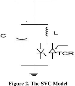
The SVC is placed at the middle of the transmission line which is generally considered to be the ideal site. Since the location of SVC strongly affects controllability of the swing modes, so the best location is at a point where voltage swings are the greatest. Normally, the mid-point of a transmission line is a good candidate for placement. The considered configuration of SVC is a thyristor controlled reactor in parallel with fixed capacitor (TCR-FC) as shown in Figure 2. The capability of this power system model at regulated the voltage will be presented at this paper under various loading conditions.
Figure 1. Single machine system with SVC
Figure 2. The SVC Model
The system dynamics is described by the following equations where the synchronous generator is represented by the classical second order model and the SVC is represented by the third one [11]:
= ω- (1)
ω= ( - ) - (ω- ) (2)
= [- + + u] (3)
Where
=
(4) For the above equations:
Power angle of the generator (in radian), ( Relative speed (in radian), ( Mechanical input power (in p.u.),
( ) Electric power of generator (in p.u.), Damping constant (in p.u.), ( Inertia constant of generator (in sec.), Reactances (in p.u.), ( Transient EMF
of generator (in p.u.), ( Infinite bus voltage (in p.u.),
( ) Susceptance of the equivalent capacitor (in p.u.), ( )
Susceptance of the inductor in SVC (in p.u.), ( ) Initial value of the (in p.u.), (K) Control gain of SVC (in p.u.),
(T) time constant of SVC, ( ) gain in the control loop (in p.u.).
The values of these parameters are listed at the appendix. The mid-bus voltage can be written as:
/ (5) Where
To accurately control the system, it is beneficial first to develop a model of the system. The main objective for the modeling task is to obtain a good and reliable method for analysis and control system development. A good model can be used in off-line controller design and implementation of the control scheme.
Most control systems driven by machines exhibit nonlinear behavior and are often difficult or unrealistic to model directly using laws of physics. In general, a linear system allows the use of more sophisticated advanced control schemes to achieve higher performance. Therefore, in this paper the system model which includes the SVC with SMIB should be linearized around the operating point. The linearization expressed in terms of state space equations since according to reference [12] optimal control problems are better solved using the state space representation.
G
The remote system bus
[image:2.612.71.281.498.613.2]After getting the state space equations and through the using of MATLAB program it can be possible to determine the plant which represents the transfer function for the operation of the power system model, this plant tested under five loading operating conditions resulted from increasing the loading state (Po) by 20% from the real load and they are:
(a) 0.4 (b) 0.6 (c) 0.8 (d) 1.0 (e) 1.2.
[image:3.612.65.296.232.387.2]The parameters of this plant affected by changing the conditions in power system model, so (Table 1) presents the effects of these five loading conditions on power system plant:
Table 1 The plant of power system model for five loading conditions
Load state (Po)
Load angle (deg)
Load angle (Rad)
The resulting plant
0.4 0.7901 16.32 0.285
0.6 0.8974 24.6 0.43
0.8 0.7942 33 0.576
1.0 0.6578 41.63 0.7266
1.2 0.4861 50.53 0.882
3. ADAPTIVE CONTROL SYSTEM
PID controller is commonly used controller in power systems due to its simple structure, strong reliability and easy realization. The control effect of the PID has the direct relations with its parameters proportion, integration and differential. However the gain settings of fixed gains controller are determined under a particular operating condition, the gain settings which are suitable for one loading condition may become completely unsatisfactory for another set of loading conditions.
Since the power system is highly stochastic due to the continuous changes at loading conditions and also the variation at the parameters of the system, the gain setting must be adapted based on off-line controller according to the self-tuning of PID parameters.
Tuning is the process of finding the controller parameters according to the systems requirements. In this paper the methods used for PID controller tuning concern in finding a model for the system and then calculate the controller parameters.
In an industrial sewing machine, it may be time consuming or dangerous to tune controllers directly on the machinery. In such cases, an accurate model must be used off-line for the tuning and verification of the controller. The self-tuning method used in this paper deals with parametric calculation based on neural networks.
The feature of an ANN is its capability to solve a complicated problem very efficiently because the knowledge about the problem is distributed in the neurons and the connection weights of links between neurons,
and information are processed in parallel. Back-propagation is an iterative, gradient search, supervised algorithm which can be viewed as Multi layer, non-linear method that can re-code its input space in the hidden layers and thereby solve hard learning problems. The network is learned using ANN technique until a good performance response is reached at any loading state.
The advantage of using ANNs to simulate processes is that, after they are continuous learning, they represent a quick and reliable way of enhancing the performance of the response of the power system model. They can also be continuously calculated under any changing.
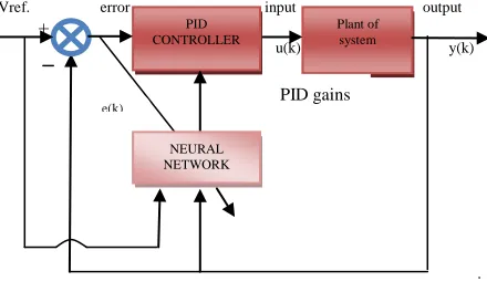
Thus, if we apply this technique to the problem of simulation and control of process, then we obtain an accurate control with a short computational time for the simulation which can be used in an efficient real-time control scheme. The PID controlling scheme which was based on ANN as a self-tuner (PID-ANN) is presented as an off-line closed loop controller as shown in Figure 3.
Vref. error input output +
u(k) y(k)
Figure 3. ANN-PID controlling closed loop system
From Figure 3 the problem at hand is that of minimizing the error e(k)which is a function of the difference between the actual response y(k)which represents the output voltage of the plant and the desired voltage response Vref. which considered as 1 p.u., so:
e(k)= Vref. – y(k)
Therefore the goal of the control system shown at Figure 3 is to establish a zero variation level between the measured plant output and the desired response.
Since the traditional PID algorithm is prone to errors and difficult to deal with highly and non-linear time varying environments and due to continuous load variation at power system it is impossible to use a fixed proportional, integral and derivative gains for the reaction of PID controller at all different changes; therefore we used neural network based on back propagation algorithm to operate as a self-tuner helping the PID controller at calculating its suitable gains parameters at different loading conditions.
So the theory of the adaptive artificial neural network-PID (ANN-PID) controller adopts the continuous changes of proportion, integration and differential control parameters through BP neural network algorithm according to the state of system where the (BP) represents the best control rule which can be used for learning the neural network. Neural network is composed of input layer, hidden layer and output layer, which fits the required calculated results by the error back propagation learning algorithm.
PID CONTROLLER
PLANT OF
SYSTEM
Plant ofsystem
NEURAL NETWORK
[image:3.612.325.545.280.412.2]4.
CONFIGURATION
OF
BACK
PROPAGATION NEURAL NETWORK
(BPNN)
The BP network is a multilayered simple network which consists of three layers BP NN and they are an input layer, hidden layer and an output layer. It contains four input neurons, five hidden neurons and three output neurons. The input neurons are the error e(k), output voltage of the plant y(k), reference voltage (Vref.) and bias, where it may become possible to adjust the gains of PID controller adaptively by the measurement of the above input neurons data depending on BP algorithm. The output neurons represented by the three tuned parameters of PID controller which represented by Kp, Ki and Kd. The structure of the network is shown at Figure 4:
Hidden layer
e(k)
y(k)
+1
Input layer +1 Output layer
Figure 4. Configuration of BP neural network
5.
ALGORITHM OF ADAPTIVE SELF-
TUNINGNEURAL
-
PID CONTROLLERUsing the BP algorithm, one can derive the self-tuning neural-PID control algorithm; it is worthy to mention that the PID controller in discrete-time control system is described as:
(6)
Where Kp, Ki, Kd are respectively the proportional, integral and derivative gains of the PID controller which should be tuned and optimized, u(k) denotes the control signal and e(k) is the error between a desired value and the
actual output y(k), that is:
(7) The control signal u(k) can be recomposed as follows:
(8)
Where f [.] is a non linear function that is concerned with , and .
By assuming that x, o isthe input and output of the neural network, the calculation steps of (ANN-PID) control system algorithm as below:
The input layer of BP neural network output:
j=1,2,…m (9)
Where m represents the nodes of input layers. The input of BP neural network hidden layer is:
Where represents the link weight of the nerve unit i of hidden layer and the nerve unitj of input layer.
The output of the ith nerve unit of BP neural network hidden layer is:
i
=1, 2…q
(11)
Where f(x) represents the bipolar sigmoid activation function of the hidden layer, that is:
The input of the final network output layer of three nodes is:
Where, represents the link weight of the nerve unit l ofthe output layer and the nerve unit i of thehidden layer. The output of the lth nerve unit of BP neural network output layer is:
l=1, 2, 3 (14)
Thus, the three outputs of the final output layer as follows:
Because of the three parameters , and can’t be negative, the activation function of output layer’s neurons
is sigmoid unipolar activation function, that is:
The superscripts (1), (2), (3) represent the input layer, hidden layer and output layer
Take the performance index function:
Where E(k) is to modify the weighs by faster descent mean using the back propagation (BP) method.
weight coefficient of BP algorithm is searched and tuned toward the negative gradient and added on an inertia coefficient to make fast convergence to the global minimum of the inertia, and they are:
Where learning rate, is the inertia coefficient and
Where:
It can be approximated as the sign function to be equal to:
Equation (20) determines the direction of the weight change and the numerical size of the change, but the rate of change of the weights by learning adjusted by the equation:
(21)
From equation (21):
From that the weight coefficient of the output layer of BP neural network is calculated as:
(k)+ (24)
Where =1, 2, 3
From equation (24):
Then equation (18) can be written as:
(k)+ (25)
Similarly, the weight coefficient of the hidden layer of BP neural network can be calculated as:
(26)
Where:
(27)
Then:
i
=1, 2, …,q
Thus, the back propagation (BP) neural network tuning control algorithm can be summarized as follows:
1. Determine the BP neural network structure, which include the input layer nodes and the number of hidden layer and the number of output layer nodes , and then gives the initial values of the hidden and output layers weight coefficient
and , Select learning rate
,inertia coefficient
.2. Obtain , y(k), in order to calculate the moment of error where: 3. Calculate the neural network NN layers of
neurons in the input, hidden and the output of the NN output layer, at output layer there are three adjustable parameters of the PID controller Kp, Ki, Kd.
4. Calculate the output of PID controller u(k). 5. Through the Neural network continuous learning
off-line it will be possible to adjust the weighting factor and to achieve adaptive adjustment of the PID control parameters. 6. Set k = k +1, return to the first step.
Thus, the performance of PID controller can be enhanced in order to get best and faster response at the plant of the power system model (SMIB-SVC) at various loading conditions.
The flowchart of the ANN-PID controlling closed loop system with the model of the plant is shown in Figure 5.
Figure 5. Flow chart of ANN-PID controlling scheme Initial values of y(k), nd e(k)
ANN as a self-tuner based on BP algorithm to adjust the parameters of PID controller
(Kp, Ki, Kd)
Calculate the output response of the system plant
Input to the PID controller which operate as an action to give the self-tuning results of
the adjusted parameters to the plant of power system y(k)
Is the error minimized e(k) zero?
stop
(22)
YES NO
6.
RESULTS
The algorithm described in this paper has been coded in MATLAB (R2009b) language. The performance of the algorithm is illustrated considering the states of five loading conditions where (Po=0.4), (Po=0.6), (Po=0.8), (Po=1.0) and (Po=1.2). The results from using (ANN-PID) controller compared with the results obtained from using (ANN) controller. The comparisons of the results were made under the five above loading condition states as below:
[image:6.612.330.543.73.214.2]Figure 6 shows the comparison between the responses of both ANN controller and ANN-PID controller at the plant of power system model when the loading condition is (Po=0.4).
Figure 6 the responses of the plant at Po=0.4 for both ANN controller and ANN-PID controller
[image:6.612.76.288.201.381.2]Figure 7 shows the comparison between the responses of both ANN & ANN-PID controllers at the plant of power system model when the loading condition is (Po=0.6).
Figure 7 the responses of the plant at Po=0.6 for both ANN controller and ANN-PID controller
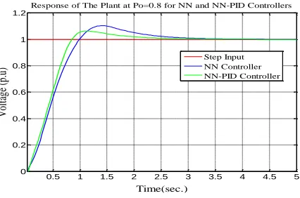
Figure 8 shows the comparison between the responses of both ANN & ANN-PID controllers at the plant of power system model when the loading condition is (Po=0.8).
Figure 8 the responses of the plant at Po=0.8 for both ANN controller and ANN-PID controller
[image:6.612.327.546.288.448.2]Figure 9 shows the comparison between the responses of both ANN & ANN-PID controllers at the plant of power system model when the loading condition is (Po=1.0).
Figure 9 the responses of the plant at Po=1.0 for both ANN controller and ANN-PID controller
[image:6.612.78.293.452.596.2]Figure 10 shows the comparison between the responses of both ANN & ANN-PID controllers at the plant of power system model when the loading condition is (Po=1.2).
Figure 10 the responses of the plant at Po=1.2 for both ANN controller and ANN-PID controller
To study the effects of both controlling schemes to get the faster and best response performance, the settling time, peak time, rise time and overshoot was investigated under various loading conditions. TABLE (2) and TABLE (3)
0.5 1 1.5 2 2.5 3 3.5 4
0 0.2 0.4 0.6 0.8 1 1.2
Time (sec.)
V
ol
tag
e
(p
.u
)
Response of The Plant at Po=0.4 for NN and NN-PID Controllers
Step Input NN Controller NN-PID Controller
0.5 1 1.5 2 2.5 3 3.5 4
0 0.2 0.4 0.6 0.8 1 1.2
Time (sec.)
V
ol
tag
e
(p
.u
)
Response of The Plant at Po=0.6 for NN and NN-PID Controllers
Step Input NN Controller NN-PID Controller
0.5 1 1.5 2 2.5 3 3.5 4 4.5 5 0
0.2 0.4 0.6 0.8 1 1.2
Time(sec.)
V
ol
tag
e
(p
.u
)
Response of The Plant at Po=0.8 for NN and NN-PID Controllers
Step Input NN Controller NN-PID Controller
1 2 3 4 5 6 7 8
0 0.2 0.4 0.6 0.8 1 1.2
Time (sec.)
V
ol
tag
e
(p
.u
)
Response of The Plant at Po=1 for NN and NN-PID Controllers
Step Input NN Controller NN-PID Controller
1 2 3 4 5 6 7 8
0 0.2 0.4 0.6 0.8 1 1.2
Time (sec.)
V
ol
tag
e
(p
.u
)
Response of The Plant at Po=1.2 for NN and NN-PID Controllers
[image:6.612.329.540.506.653.2]show the effects of ANN controller and ANN-PID controller during the previous mentioned parameters.
[image:7.612.317.530.78.220.2]
TABLE 2 RESULTS WHEN ANN CONTROLLER IS USED
TABLE 3 RESULTS WHEN ANN-PID CONTROLLER IS USED
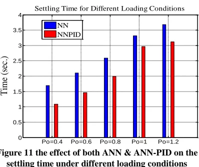
[image:7.612.332.537.308.448.2]Figure 11 shows the effect of ANN & ANN-PID on the settling time (Ts)
Figure 11 the effect of both ANN & ANN-PID on the settling time under different loading conditions
Figure 12 shows the effect of ANN& ANN-PID on the rising time (Tr).
Figure 12 the effect of both ANN & ANN-PID on the rising time under different loading conditions
Figure 13 show the effect of ANN & ANN-PID on the peak time (Tp).
Figure 13 the effect of both ANN & ANN-PID on the peak time under different loading conditions
7. CONCLUSIONS
The proposed control algorithm for SVC can rapidly track the voltage reference of the SVC system and improve the performance of the SVC system observably.
PID controllers are simple, widely used control method, but the difficulties arise from tuning the PID parameters to meet the desired specifications for a wide range of operating conditions. From the simulation results obtained for different loading conditions for the self tuning (Artificial Neural Network-Proportional Integral Derivative) (ANN-PID) controller compared with (Artificial Neural Network) (ANN) controller it can be concluded that ANN based PID controller is faster, with less peak overshoot and settling time than the ANN controllers. The superiority of this adaptive controlling system can be established under different loading conditions, so the proposed adaptive SVC control system can synthetically compensate voltage control with faster response and higher compensation precision.
Po=0.4 Po=0.6 Po=0.8 Po=1 Po=1.2 0
0.2 0.4 0.6 0.8 1 1.2 1.4 1.6 1.8
T
im
e
(s
ec
.)
Peak Time for Different Loading Conditions
NN NNPID
load state Po
Settling time Ts
Rising time Tr
Peak time Tp
Max. value
μp Overshoot
0.4 1.696 0.487 0.986 1.0802 8.02%
0.6 2.102 0.598 1.196 1.0841 8.41%
0.8 2.59 0.693 1.41 1.104 10.4%
1.0 3.312 0.777 1.62 1.159 15.9%
1.2 3.684 0.863 1.75 1.1882 18.82%
load state Po
Settling time Ts
Rising time
Tr
Peak time Tp
Max. value
μp Overshoot
0.4 1.0848 0.419 0.6825 1.0511 5.11%
0.6 1.459 0.524 0.888 1.0537 5.37%
0.8 1.9924 0.611 1.125 1.0647 6.47%
1.0 2.96 0.7 1.35 1.1084 10.84%
1.2 3.12 0.733 1.476 1.1405 14.05%
Po=0.4 Po=0.6 Po=0.8 Po=1 Po=1.2 0
0.5 1 1.5 2 2.5 3 3.5 4
T
im
e
(s
ec
.)
Settling Time for Different Loading Conditions
NN NNPID
Po=0.4 Po=0.6 Po=0.8 Po=1 Po=1.2 0
0.1 0.2 0.3 0.4 0.5 0.6 0.7 0.8 0.9
T
im
e
(s
ec
.)
Rising Time for Different Loading Conditions
[image:7.612.83.282.383.550.2]8.
REFERENCES
[1] A. Subramanian, G. Ravi and D. Arun Gopal: “Loss Minimization and Voltage Profile Improvement Incorporating Multiple SVC Using PSO Algorithm”, International Journal of Computer Applications, vol. 46, No. 22, PP. 15-20, May 2012.
[2] A. Luo. The Technology and Equipment for Harmonic Suppression and Compensation of the Reactive Power of Power Network. Beijing:China Power Publishing House, 2006.
[3] E. Zhou. Application of static var compensators to increase power system damping. IEEE Transactions on Power Systems, 1993, 8(2):655 – 661.
[4] Alisha Banga and S.S. Kaushik: “Modeling and Simulation of SVC Controller for Enhancement of Power System Stability”, International Journal of Advances in Engineering & Technology, vol. 1, Issue 3, PP. 79-84, July 2011.
[5] X. Yu, M. Khammash, V. Vittal. Robust design of a damping controller for static var compensators in power systems. IEEE Transactions on Power Systems, 2001, 16(3): 456 – 462.
[6] A. Barnawi, A. Albakkar, O. P. Malik. RLS and Kalman filter identifiers based adaptive SVC controller. The 39th North American Power Symposium. Las Cruces, New Mexico, 2007: 615 – 622.
[7] X. Du, L. Peng, L. Zhou. A hybrid reactive power compensation system consisting of multi capacitor banks and a SVG. Power System Technology, 2008, 32(14): 39 – 43.
[8] C. Cheng, Y. Y. Hsu. Damping of generator oscillations using an adaptive static var compensator. IEEE Transactions on Power Systems, 1992, 7(2): 718 – 725.
[9] Y, Wang. Y, Lin. G, Guo. Robust nonlinear coordinated generator excitation and SVC control for power systems. International Journal of Electrical Power and Energy Systems, 2000, 22(3): 187 – 195. [10] M. Noroozian, M. Ghandhari, G. Andersson, et al. A
robust control strategy for shunt and series reactive compensators to damp electromechanical oscillations. IEEE Transactions on Power Delivery, 2001, 16(4): 812 – 817.
[11] Y. Ma, S. Chen, and B. Zhang, "A Study on Nonlinear SVC Control for Improving Power System Stability,"
TENCON'93, Proceedings, Computer,
Communication, Control and Power Engineering, 1993 IEEE Region 10 Conference, Vol. 5, pp. 166 – 169.
[12] Ogata, K. (2004), Modern Control Engineering, 4th Edition, Pearson Education (Singapore) Pte. Ltd, India.
[13] Samir A. Al-Baiyat, “Design of a Robust SVC Damping Controller Using Nonlinear H∞ Technique”, the Arabian journal for science and engineering, Vol. 30, No. 1B, PP. 65-79, April 2005.
APPENDIX
The power system data are as follows [13]: H=6.0 sec, D=.0055, K=1.2, T = 0.2, xl = 0.45 p.u,
x2 = 0.3 p.u, ωo = 377.0, E'= 1.1, Vt =1, Blo = 0.58, Bc = 0.8