Comparative Study of BPSK and QPSK for Wireless
Networks over NS2
Anwar Ul Haque
COCIS
Karachi Institute Of Economics and Technology, Karachi, Pakistan
Muhammad Saeed
Department of Computer Science, University of Karachi.
Karachi, Pakistan
Farhan Ahmed Siddiqui
Department of Computer Science, University of Karachi.
Karachi, Pakistan
ABSTRACT
Modulation plays an important role in transmission of single from transmitter to receiver in all communication systems. But it is vital in wireless communication and a lot of communication features including (data rate, error rate, symbol rate, bandwidth etc) depends upon it. In NS2 wireless network simulation BPSK is used for digital encoding and modulation of data [1,2]. The BPSK method is used by wireless/phy object that is inherited by Modulation Class. In this paper QPSK is used in place of BPSK and analyzed in terms of data rate, error rate and power consumption in NS 2 simulation. Also the proposed code for QPSK modulation is given in this paper.
General Terms
BPSK (Binary Phase Shift Keying), QPSK (Quadrature phase shift keying), Nb (Spectral noise of a single bit), Eb (Bit Energy during transmission), Sb (bit state representation), Pb (Bit Error Rate), φ(t) (signal space).
Keywords
Modulation Techniques, Wireless Networks, Network Simulator 2 (NS2).
1.
INTRODUCTION
The study is done with the intention to ensure the realistic approach of simulation in NS2 [11] for wireless and mobile networks and to test the bandwidth exhaustion phenomena for wireless networks. Over the years only BPSK has been used as the modulation technique for the simulations of mobile and wireless communication in NS2 [1]. By considering the limitations of BPSK and the enhanced capabilities of QPSK we have implemented and tested the QPAK module over NS2. In this paper first we have discussed BPSK and its implementation over NS2 in section 2 then QPSK and its design and implementation in section 3. The comparative study of performance of both techniques will be covered in section 4.
[image:1.595.328.532.231.408.2]2.
BINARY PHASE SHIFT KEYING
NS2 uses BPSK (Binary Phase Shift Keying) for digital encoding/modulation of signal in wireless network simulation or in mobile network simulation. The modulation code is available in modulation.cc defined via modulation.h having a hierarchy (Fig#1) as follow:Fig 1: mudulations.cc and its dependencies
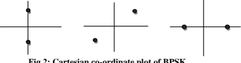
BPSK (binary phase shift keying) also termed as Phase reversal keying is one of the form of Phase shift keying. BPSK consists of two points of representing binary information and located 180 degree apart from each other [3], [4]. The location of points on Cartesian coordinate is arbitrary they can be plotted any where having any degree with reference but they have to be 180 deg apart from each other (Fig#2). Cartesian coordinate plot is also referred to as constellation.
Fig 2: Cartesian co-ordinate plot of BPSK
The transmission rate of BPSK in NS2 wireless network simulation is one bit per symbol that’s why it is also called symbol rate.
2.1
Implementation of BPSK for NS2:
𝑺𝒃 𝐭 = {(𝟐𝑬𝐛/𝑻𝐛) × 𝒄𝒐𝒔(𝟐𝝅𝒇𝐜+ 𝛑(𝟏 − 𝐧))} Where n=0,1
For binary bit 0: Taking n=0.
𝑺𝟎= (𝟐𝑬𝟎/𝑻𝟎) × 𝒄𝒐𝒔(𝟐𝝅𝒇𝐜𝐭 + 𝛑(𝟏 − 𝟎))
𝑺𝟎= (𝟐𝑬𝟎/𝑻𝟎) × 𝒄𝒐𝒔(𝟐𝝅𝒇𝐜𝐭 + 𝛑)
[image:1.595.319.565.536.601.2]If signal space 𝝋 𝒕 = (𝟐𝑻)𝐜𝐨𝐬(𝟐𝛑𝐟𝐜𝐭) ) Then
𝑺𝟎= − (𝑬𝟎𝝋 𝒕 )
𝑬𝟎= 𝒆𝒏𝒆𝒓𝒈𝒚 𝒃𝒊𝒕
For binary bit 1: Taking n=1
𝑺𝟏= (𝟐𝑬𝟏/𝑻𝟏) × 𝒄𝒐𝒔(𝟐𝝅𝒇𝐜𝐭 + 𝛑(𝟏 − 𝟏))
𝑺𝟏= (𝟐𝑬𝟏/𝑻𝟏) × 𝒄𝒐𝒔(𝟐𝝅𝒇𝐜𝐭)
If signal space 𝝋 𝒕 = (𝟐𝑻)𝐜𝐨𝐬(𝟐𝛑𝐟𝐜𝐭) Then
𝑺𝟏= (𝑬𝟏𝝋 𝒕 )
𝑬𝟏= 𝒆𝒏𝒆𝒓𝒈𝒚 𝒃𝒊𝒕
Bit Error Rate in BPSK in NS2:
𝑷𝐛=𝟏𝟐𝒆𝒓𝒇𝒄 (𝑬𝒃/𝐍𝟎)
Where 𝑬𝟎=Energy/bit,
𝑵𝒃=Noise power spectral density
The above equation also refers to as symbol error rate. [3], [6]
[image:2.595.48.278.389.466.2]The system model of BPSK used in NS2:
Fig 3: BPSK model implemented in NS 2 [9],[10]
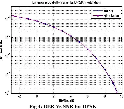
[image:2.595.47.283.515.723.2]Bit Error Rate Vs Signal to noise ration graph for BPSK:
Fig 4: BER Vs SNR for BPSK
The graph in fig 4 depicts that as we increase the power from transmitter for transmitting data to long distance while using
binary phase shift keying the error rate increases exponentially.
The section below list the discrepancies faced in NS2 simulation due to using binary phase shift keying.
There are certain deficiencies available in BPSK which would not allow NS 2 simulation of wireless network to provide realistic aspect of wireless communication. The deficiencies are as under:
1. Since BPSK uses two bits scheme or can transmit one bit/symbol so it provides very slow data rate & does not provides actual representation of high data rate in wireless network during simulation.
2. The error rate in BPSK is high as there is only one bit for representing data so slight error causes the moving node in NS2 to request for retransmission of signal or raises no message or data receive flag high.
3. The orientation of bits is 180 degree apart from each other so it generates high distortion at the time of decoding at receiving end due to the non-linear characteristic of amplifiers so computer system has to provide extra processing for wireless network simulation to synchronize with transient changes of bit in NS2 simulation.
In the light of above discrepancies it is proposed that instead of BPSK, QPSK modulation may be used for NS2 simulation of wireless networks. [3]
3. QPSK (QUADRATURE PHASE SHIFT
KEYING)
[image:2.595.320.538.546.627.2]If we add two more binary information symbols in BPSK then it becomes QPSK. There are 4 signal elements in QPSK instead of two. Each signal element is 90o apart from each other on the Cartesian coordinates. QPSK can carry twice data rate of BPSK and has less susceptibility to noise as compare to BPSK. QPSK constellation (Fig# 5) is as show below.
Fig 5: Constellation of QPSK
3.1 Implementation of QPSK for NS2
The implementation of QPSK is more ease than BPSK and has the capability of extension in terms of data rates via 4QPSK, 8QPSK, 16QPSK and 32QPSK.
Generalized equation of QPSK:
𝑺𝒊 𝒕 = {(𝟐𝑬𝒔/𝑻) × 𝒄𝒐𝒔(𝟐𝝅𝒇𝒄𝒕 + (𝟐𝒏 − 𝟏)𝝅/𝟒)}
n=1, 2, 3, 4
BPSK i/p
10100110 BPSK Mod
BPSK Dmod
o/p 10100110
± (𝑬𝟏𝝋 𝒕 ) ± (𝑬𝟏𝝋 𝒕 ) BPSK
Converting in signal space:
𝝋𝟏 𝒕 = 𝑻×𝒄𝒐𝒔(𝟐𝝅𝒇𝟐 𝒄𝒕)
𝝋𝟐 𝒕 =
𝟐
𝑻 × 𝒔𝒊𝒏(𝟐𝝅𝒇𝒄𝒕)
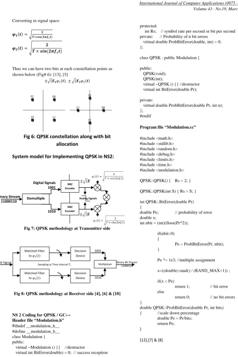
Thus we can have two bits at each constellation points as shown below (Fig# 6): [13], [5]
[image:3.595.29.517.35.768.2]± (𝑬𝟏𝜑1 𝒕 , ± (𝑬𝟏𝜑2 𝒕
Fig 6: QPSK constellation along with bit
allocation
System model for Implementing QPSK in NS2:
Fig 7: QPSK methodology at Transmitter side
Fig 8: QPSK methodology at Receiver side [4], [6] & [10]
NS 2 Coding for QPSK / GC++ Header file “Modulation.h”
#ifndef __modulation_h__ #define __modulation_h__ class Modulation { public:
virtual ~Modulation () {} //destructor
virtual int BitError(double) = 0; // success reception
protected:
int Rs; // symbol rate per second or bit per second private: // Probability of n bit errors
virtual double ProbBitError(double, int) = 0; };
class QPSK : public Modulation { public:
QPSK(void); QPSK(int);
virtual ~QPSK () {} //destructor virtual int BitError(double Pr);
private:
virtual double ProbBitError(double Pr, int n); };
#endif
Program file “Modulation.cc”
#include <math.h> #include <stdlib.h> #include <random.h> #include <debug.h> #include <limits.h> #include <time.h> #include <modulation.h> QPSK::QPSK() { Rs = 2; } QPSK::QPSK(int S) { Rs = S; } int QPSK::BitError(double Pr) {
double Pe; // probability of error double x;
int nbit = (int)(floor(Pr*2)); if(nbit>0)
{
Pe = ProbBitError(Pr, nbit); }
Pe *= 1e3; //multiple assignment x=((double) rand() / (RAND_MAX+1)) ; if(x < Pe)
return 1; // bit error else
return 0; // no bit errors }
double QPSK::ProbBitError(double Pr, int bits) { //scale down percentage
double Pe = Pr/bits; return Pe;
}
[12],[7] & [8]
Demultiple xer NRZ Encoder Binary Stream 11000110 NRZ Encoder 1001 1010
Digital Signals ± (𝑬
± (𝑬
Analog Signals
𝜑1 𝑡 =
2 𝑇 × 𝑐𝑜𝑠(2𝜋𝑓𝑐𝑡)
𝜑2 𝑡 =
2 𝑇 × 𝑠𝑖𝑛(2𝜋𝑓𝑐𝑡)
QPSK Signal Binary Bit Stream
11000110
Matched Filter to 𝜑1 𝑡
Matched Filter to 𝜑2 𝑡
Decision Device
Decision Device
Sampling at Time Interval 𝑇𝑠
1001
1010
[image:3.595.74.260.215.336.2]4. COMPARISON OF BPSK AND QPSK
The equation below is the ratio of Energy consumed in Bit to the signal spectral noise and represent bit error rate in QPSK.
𝑃ℎ= 𝑄
2𝐸𝑏
𝑁𝑜
[image:4.595.321.540.119.249.2]Since the bit error rate for BPSK and QPSK is similar thus it by using QPSK we can transmit twice amount of data on the same channel with the same bandwidth. If we extend the modulation using 4 QPSK, 8QPSK then we can achieve higher data rate on little increase in Bit error rate as compare to BPSK. The comparison graph (Fig# 9) represents the statement in pictorial form.
Fig 9: Comparison of QPSK Vs BPSK in terms of BER
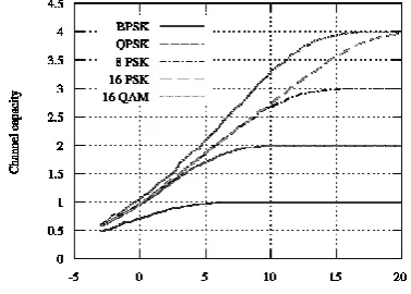
The signal to noise ratio for BPSK is very low means that it provides high immunity to noise as compare to the signal floating through the medium. The analysis is on matlab with BPSK, QPSK, 4QPSK, 8 QPSK and QAM and it is seen that the by using QPSK or higher order QPSK we can achieve high SNR thus we can be sure of less noise in the channel during transmission. The pictorial information (Fig# 10) provides clarity to statement.
Fig 10: SNR in QPSK or Higher order modulation
[image:4.595.48.289.262.450.2]After Implementing the QPSK in NS2 for simulation of wireless network the time to packet type graph shows the following continuity in the communication with respect to time (Fig# 11).
Fig 11: Packet Vs Time graph by NS 2
[image:4.595.317.539.288.462.2]Since QPSK provides extra bit rate on the same BER with high SNR so the count of messages on the moving node is also constant and there very less or no amount of discontinuity in communication which was available earlier in BPSK (Fig# 12).
Fig 12: discontinuity curve
The pictorial information below provides the detail in continuity of exchange of TCP from transmitter to the moving node and ensures there is no delay or discreetness in communication. This is due to the QPSK modulation which was not available in BPSK (Fig# 13).
Fig 13: Delay in TCP/IP
2. CONCLUSION
[image:4.595.316.540.565.729.2] [image:4.595.67.256.583.718.2]simulation. The QPSK modulation is tested and analyzed with different types of wireless topologies and is comfortable with all topologies providing good results. So it can easily be integrated as a separate module utilizing the QPSK modulation methodology in NS II or NS III for deploying wireless network and related simulations. Which will provide space to users or students to develop high bandwidth requiring applications or elements in wireless on NS II or NS III.
3.
REFERENCES
[1]Qi Chen , Felix Schmidt-Eisenlohr et al. 2007, “Overhaul of IEEE 802.11 Modeling and Simulation in NS-2”, Proceedings of the 10th ACM Symposium on Modeling, analysis, and simulation of wireless and mobile systems [2] Mirghiasaldin Seyedebrahimi and Xiao-Hong Peng,
“Investigation of PHY, MAC and APP Layers for Adaptive and Cross-Layer Optimization in IEEE802.11 WLAN”, Computer and Information Technology (CIT), 2010 IEEE 10th International Conference on.
[3] C. E. SHANNON, 1948, “A Mathematical Theory of
Communication”, The Bell System Technical Journal, Vol. 27, pp. 379–423, 623–656, July, October, 1948. [4] Louis Frenzel, 2007, Principles of Electronic
Communication Systems,3rd Edition
[5] Wireless Communication & Networks by William Stallings.
[6] Wireless Communication by Andre Goldsmith [7] An Introduction to C++ by Björn Fahller. [8] Thinking in C++ by Bruce Eckel
[9] Digital Modulation & coding by Stephen G Wilson [10] Modulation by MAX Reger
[11] “Network Simulator ns-2,” http://www.isi.edu/nsnam/ns/. [12] C++ How to Program by Dietel & Dietel.
[13] Fundamentals of Wireless Communication by David Tse