Survey of Fault Prediction Methods in Object
Oriented Systems
Rajkumar. N
SVS college of Enggcoimbatore Tamilnadu
Viji.C
SVS college of Enggcoimbatore Tamilnadu
Duraisamy.S
Sri Krishna college of Engg &tech coimbatore
Tamilnadu
ABSTRACT
Develop an efficient system is one of the main challenges for software developers, who has been concerned with reliability related issues as they build and deployed. This paper surveys various fault prediction techniques and measuring quality parameters in object oriented systems. The survey includes traditional techniques like Fault tree analysis , Information theoretic approach , coupling & cohesion measurement and conceptual cohesion and coupling. The utility of each technique based on structural and instructor information of class. Each technique deals with various parameters for predicting the software fault .The fault prediction improves the software reliability and quality.
Keywords
Coupling, Cohesion, Fault Tree Analysis, Latent Semantic Indexing, Information Theory Approach, Fault Prediction.
1.
INTRODUCTION
To release an error free software is the dream of every software developer. In order to achieve that zero defect product companies spend 50 to 80% of their software development effect on testing. Therefore reducing testing effort may increase productivity, reduce costs and optimize resources. Software design is the backbone of the software development Lifecycle. Finding the faulty modules in earlier phase give effective and efficient test plan execution. Object oriented software from structured software in terms of its concept and real world modelling concepts that take the form of object oriented design ideas. A fundamental constraints of object oriented modelling and design is the object, which combines both data structure and behavior in a single entity. Object oriented technology provides a product with higher quality, reliability and lower cost. This quality is achieved by predicting the fault in earlier phases.
In the paper there are several approaches to predicting the fault in object oriented systems. Many methods using structural information like attributes and methods, others are using unstructured information like comment lines. The structural metrics are mostly investigated category of cohesion metrics and includes the lack of cohesion in methods (LCOM), Conceptual Coupling between Object Classes (CCBO). Other methodologies use failure cases and information flow based metrics. The structural metrics are based on the definition of the relationship between methods, system representation and counting mechanism.
Conceptual cohesion and coupling use the comment line argument and measure the coupling and cohesion of the class. Coupling and cohesion use the structural information like variable and methods. The Information theory approach uses the flow graph for finding the coupling and cohesion. Minimum coupling and higher cohesion give a good quality
product. Fault tree analysis uses the possible faulty cases of each module. That will help to predict the fault.
2. FAULT PREDICTION USING
COUPLING AND COHESION OF
CLASSES
It is more important to maintain software quality, all related attributes and relationship between the attributes. [1] Many software metrics have been established in the past. In structured design and programming the importance of coupling and cohesion as main attributes related to the goodness of decomposition has been well known, software developers are trying to develop the system with low coupling and high cohesion. That will make the product more reliable and more maintainable. [15,6,7,18] Coupling and cohesion are measured by using the structural information like methods and attributes.
There are different types of coupling [1]:
Data coupling: communication via scalar parameters.
Stamp-Coupling: dependency induced by the type of structured parameters.
Control Coupling: parameters are used to control the behavior of a module.
Common Coupling: communication via shared global data.
Content Coupling: one module shares and/or changes the meaning of another module.
For object oriented software, [20,17,16,10] the coupling has not been considered with similar priorities. There are two main reasons for this negligence:
1. In structured design, there is some semantic procedure to decompose a system into small subsystem. Therefore the syntactic aspect like coupling, size etc. Plays a major role. At the same time in the object oriented paradigm, the main principle for system decomposition is the mapping of objects of the problem domain into classes or subsystems in the analysis/design model, thus reducing the relative importance of syntactic criteria. 2. Object oriented analysis and design trying to integrate
the data and related functionality into objects. This policy reduces coupling between the objects. So the control coupling is not important for a structured design.
In object oriented mechanism it does not assure to achieve minimum coupling. There is some reason to study coupling in object-oriented systems: [7,9,11,14]
1. Sometimes data or operations do not assign to one or another class, so the designer needs some additional criteria for such assignment.
system, the number of variants of interdependency rises in comparison to conventional systems.
3. The principles of encapsulation and data abstraction, although fundamental to object-orientation, may be violated to different extents via the underlying programming language.
This leads to different strength of real coupling which should be taken into account. Thus, coupling seems to be even more important in object-oriented systems. Coupling of client objects to a server object make a change in the dependencies. The strong coupling, make a larger change in client whenever a serious change in server, high coupling between the objects makes harder to understand. Low coupling makes easy to understand, maintainability of objects. High coupling increases the possibility of remote effects, when errors in one object also affect the related object. Low coupling makes easier track and debug the errors and improves testability. Coupling is one of the most important internal attributes of a software, we must consider the cohesion because of the dual nature of these two attributes. Trying to optimize a design with respect to the coupling between abstractions (modules, classes, subsystems...) Alone would trivially produce to a single larger abstraction with no coupling at the given level of abstraction.
Definition 1: (Object oriented concepts): A class provides the definition of structure[1] (instance variables) and behavior (methods) of similar kinds of entities, an object is an instance of its respective class. Classes may be organized in inheritance hierarchies as super and sub classes.
Definition2: Object coupling (OC) represents the coupling resulting from state dependencies between objects during the run-time of a system.
Definition3: Class coupling (CC) represents the coupling resulting from implementation dependencies in a system.
2.1 COUPLING
Chidamber and Kemerer also define RFC (Response for a Class) as the union of the protocol a class offers to its clients and the protocols it requests from other classes. Measuring the total communication potential, this measure is obviously related to coupling and is not independent of coupling between the class[1,18,20].
Strength 1: Accessing the interface of any server class SC, provided SC is a stable class or features at least a stable interface, the most harmless type of Class coupling occurs, as no change dependencies are introduced.
Strength 2: Changing the interface of an SC method called via an object local to one of the CC's methods, only this latter method needs to be changed correspondingly. The same argument applies to the case where SC is the type of a parameter of a CC method.
Strength 3: Changing the interface of an SC method invoked via a message sent to one of the CC's instance variables of class SC, due to the class scope of instance variables, potentially all methods of CC are affected. This is why this case is less favourable than the above. Similarly, changing the interface of a method of the super class SC of CC affects all methods of CC are calling this super- class method. Thus, again potentially all methods of CC may be affected. As a global variable is accessible from all methods of a class, the same argument applies for global variables, too.
Strengths 4 and 5: Following the same arguments as for strengths 2 and 3 and noticing that change dependencies are generally stronger when breaching the information hiding principle, these assignment results.
2.2 COHESION
Cohesion is an important attribute corresponding to the quality of the abstraction caught by the class under consideration. Good abstractions typically exhibit high cohesion. The original object oriented cohesion metric as given by Chidamber and Kemerer (and clarified by the same authors) represents an inverse measure for cohesion. They define Lack of Cohesion in Methods (LCOM) as the number of pairs of methods operating on disjoint sets of instance variables, reduced by the number of method pairs acting on atleast one shared instance variable.
The definition given is reproduced below:
Consider a Class C1 with n methods M1, M2,.,.,Mn. Let {Ij} = set of instance variables used by Method Mj. There are n such sets {I1}... {In}
Let P = {(Ii, Ij) | Ii∩Ij= ø} and
Q = {(Ii, Ij) | Ii∩Ij≠ ø}. If all n sets {I1}... {In} are ø then let P = ø. LCOM = |P| - |Q|.
If |P| > |Q| = 0 otherwise. So, LCOM is 2 - 1 = 1
Although the principle idea behind this definition seems very sensible, the resulting cohesion metric exhibits several anomalies with respect to the intuitive understanding of the attribute, the most important of which will be explained below.
The Lack of Cohesion in Methods metric calculations.
LCOM 1: Take each pair of methods in the class and determine the set of fields they each access. If they have disjointed sets of field accesses, the count R increases by one. If they share at least one field access, S increases by one. After considering each pair of methods: [1]
RESULT = (R > S) ? (R - S) : 0
A low value indicates high coupling between methods. This also indicates the potentially high reliability and good class design.
LCOM 2: This is an improved version of LCOM1. Say you define the following items in a class:
me: Number of methods in a class ac: Number of attributes in a class
meA: Number of methods that access the attribute a
sum(meA): Sum of all meA over all the attributes in the class mPr: Number of private methods in a class
mPub: Number of public methods in a class mPro: Number of protected methods in class
mPr+mPro): sum of all (mPr+mPro) over all the attributes in the class
LCOM2 = 1- sum (meA) / (me*ac)
If the number of methods or variables in a class is zero (0), LCOM2 is undefined as displayed as zero.
LCOM 3: This is another improvement on LCOM1 and LCOM2 It is defined as follows: [1]
LCOM 4: This is another improvement on LCOM, LCOM2 and LCOM3 It is defined as follows:
LCOM4= (me – [sum (meA) –sum (mPr+mPro)]/ac) / (me-1) Where me, ac, meA, sum (meA),mPr, mPub, mPro are as defined in LCOM2.
LCOM5: This is another improvement on LCOM, LCOM2, LCOM3 and LCOM4
It is defined as follows:
LCOM5={ [ (1/a) ( u(Aj) ) ] – m}/(1 – m) Where: a = No of attributes or instance variables u(Aj)=number of Methods that access attribute Aj m = No of Methods in the Class.
u(Aj)is summed over all the attributes j = 1-- n
3.FAULT
PREDICTION
USING
CONCEPTUAL
COUPLING
AND
COHESION METRICS FOR OBJECT
ORIENTED SYSTEMS
Coupling and cohesion measures confine the degree of interaction and relationships among source code elements, like methods, and attributes in object-oriented (OO) software systems [13][42][40][32]. In an object oriented system the classes must have high cohesion and low coupling them.[4][8][13] These properties makes easy to understand, testing efforts, reuse, and maintainability. First we deal with Conceptual Coupling between Object classes (CCBO)[32], is based on the well-known CBO coupling metric, while the other metric, Conceptual Lack of Cohesion in Methods (CLCOM5), is based on the LCOM5 cohesion metric.[26][28][42] The proposed new measure for the cohesion & coupling of classes in OO software systems based on the analysis of the unstructured information embedded in the source code, such as comments and identifiers. The measure, named the Conceptual Cohesion of Classes (C3)[39], is used to measure textual coherence. C3 is based on the analysis of textual information in the source code, expressed in comments and identifiers. Latent Semantic Indexing (LSI), to extract, represents, and analyzes the textual information from the source code. Our measure of cohesion can be interpreted as a measure of the textual coherence of a class within the framework of the entire system.the comments are created by the developer for future reference.
3.1 Latent Semantic Indexing
LSI is a machine learning model, it introduces representations of the meaning of words by analyzing the relation between the words and documents. LSI is a quantity based statistical method for suggest and representing aspect of the meanings of words and passages reflective of their usage in large bodies of text.[3,2,12] LSI is based on the vector space model (VSM), it generates a real valued description for documents of texts. Finally LSI captures the meaning of the entire passage in the document. The central concept of LSI is that the information about the contexts in a particular word appears or does not appear provides a set of mutual constraints that determines the similarity of meaning of sets of words to each other.
LSI was originally developed in the context of IR as a way to solve problems with phrase and synonyms that occurred with the vector space model. Some words appear in the same contexts and an important part of word usage patterns are accidentally unclear and insufficient. The method used by LSI to capture the important semantic information is dimension reduction, selecting the most important dimensions of Co-occurrence matrix (words by context) decomposed using singular value decomposition (SVD)[2]. Finally LSI
gives a similarity between two samples of text in an automatic unsupervised way’s relies on an SVD of a matrix (word context) divided from a corpus of natural text that pertains to knowledge in the particular domain of interest. According to the mathematical formulation of LSI, the term combinations that occur less frequently in the given document collection tend to be not allowed from the LSI subspace. LSI reduces less frequently Co occurring terms, in the same way the most frequent terms are also eliminated from the analysis. The formalism behind SVD is rather complex and too lengthy to be presented here Once the documents are represented in the LSI subspace, the user can compute similarity measures between documents by the cosine between their corresponding vectors or by their length. These measures can be used for clustering similar documents together to recognize “concepts” and “topics” in the corpus. This type of usage is typical for text analysis tasks.
3.2 Conceptual Cohesion & Coupling Metrics
The definitions of the new conceptual cohesion and coupling of classes .[3,5] The source code of the software system is parsed and transformed into a corpus of textual documents where each document corresponds to the implementation of a method. The LSI technique takes the corpus as an input and creates a term by document matrix, which captures the dispersion and Co occurrence of terms in class methods. SVD is used to construct a subspace, referred to as the LSI subspace. All methods from this matrix are represented as vectors in the LSI subspace. The cosine similarity between two vectors is used as a measure of conceptual similarity between the two methods and is supposed to determine shared conceptual information between two methods in the context of the entire software system. This mechanism to capture conceptual similarity among documents has been introduced before in the Conceptual Coupling of Classes and Conceptual Cohesion of Classes measures. Some of the definitions for the model CCBO, an CLOM5 have been presented.
Principal Definitions
Definition 1: (System, Classes, Methods).
We define an OO system as a set of classes C = {c1, c2…cn} with the number of classes in the system n = |C|. A class has a set of methods. For each class c∈C, M(c)={m1, …, mt} represents its set of methods, where t = |M(c)| is the number of methods in a class c. The set of all the methods in the system is denoted as M(C).
An OO system C can be also viewed as a set of connected graphs GC = {G1,..,Gn} with Gi representing class ci. Each class ci∈C is also represented by a graph Gi∈GC such that Gi = (Vi, Ei),whereVi= M(ci) is a set of vertices corresponding to the methods in class ci and Ei⊂Vi,Vi is a set of weighted edges that connect pairs of methods from the class.
Definition 2: (Conceptual Similarity between Methods). The conceptual similarity between the methods (CSM) mk∈M(C) and mj∈M(C), CSM (mk, mj), is computed as the cosine amid two vectors vmk andvmj, representing mk and mj in the[3] LSI semantic space:
CSM(mk,mj)=
vm kT vm j vm k 2 x vm j 2
As defined, the value of CSM(mk, mj) ∈ [-1, 1], as CSM is a cosine similarity in the LSI space. In order to fulfil non-negativity property of software metrics, we refine CSM as the following:
CSM1(mK,mj)= CSM mk, mj if CSM mk, mj > 0
CSM1 has been used as a base for defining C3 [39]andCoCC[40] measures before.
Definition 3: (Parameterized Conceptual Similarity)
In our work we define conceptual cohesion and coupling metrics utilizing counting mechanisms, stemming from existing structural metrics, which are sensitive to the input information such as nodes and edges (e.g., methods and attribute references). Thus, in this work we introduce a notion of a parameterized conceptual similarity, which distinguishes between significant and non-significant conceptual interactions among methods of classes. [12,24]In particular, we guess that it is possible to empirically derive a threshold for a given software system to distinguish between strong and weak conceptual similarities. More formally, we define parameterized CSMP as:
CSMP(mk,mj,t)= 1 if CSM1 mk, mj > t
𝑒𝑙𝑠𝑒 0
The particular threshold t depends on the specific software system. [3] In our previous experience, the absolute value of the cosine similarity cannot be used as a reliable indicator of the presence or absence of conceptual relationships among pairs of methods as more comprehensive analysis of similarity distributions is required. One of the main research questions in our empirical evaluation is centered on empirically deriving such a threshold and analysis of the impact on the choice of threshold values on the resulting metrics.
3.3 Conceptual Lack of Cohesion in Classes
CLCOM5[3] using CSMP as the foundation for computing conceptual similarities among methods of classes, however, in terms of counting mechanism we rely on one of the ideas from previously defined structural metrics, namely LCOM5, graph based cohesion metric. The main difference between our metric, CLCOM5 and C3, conceptual cohesion of classes metric, is that we define a parameterized version of cohesion metric using a different counting mechanism:
CLCOM 5(c, x) = NoCC(G),
Where NoCC identifies the number of connected components in the graph GC= (M(c), E), c ∈C, E ∈ M(c), and (mk, mj) ∈ E if CSMP(mk, mj, t)=1.
3.4 Conceptual Coupling between Object Classes
The definition of CCBO depend on on previous definitions for CoCC metric. [25]We provide these definitions and explain how we adjusted them in the current work.
Let ck∈ C and cj∈ C be two distinct (ck≠cj) classes in the system. Each class has a set of methods {mk1, …,mkr}, where r = |M(ck)| and M(cj) = {mj1, …,mjt}, where t = |M(cj)|. Between every pair of methods (mk, mj) there is a similarity measure CSMP(mk, mj). We can similarly define the conceptual similarity between two classes cj and ck, that is CSCP , as follows:
CSCP(ck,cj,t)= 1 if CSC1 ck, cj ≥ 𝑡
𝑒𝑙𝑠𝑒 0
The definition ensures that the conceptual similarity between two classes is symmetrical, as CSC(ck, cj) = CSC(cj, ck). In this case we use class granularity to build the corpus. This is the main difference between computing CLCOM5[3] [2] and CCBO metrics. We refine the conceptual similarity for a class c as the following:
CCBO(c,t)= ck ∈ C,c≠ck CSCP(c, ck, t)
This is the sum of the parameterized conceptual similarities between a class c and all the other classes in the system.
4. FAULT TREE ANALYSIS
Fault Tree Analysis (FTA)[37,22] was introduced in the 1960s, it is a technique used for improving reliability, its primary purpose for identifying circumstances that could cause a system to reach a hazardous state. FTA is a powerful static analysis tool to give a specific hazardous state, FTA uses backward searching technique to identify conditions that would cause the system to reach that state. FTA will search all possible combinations of the conditions that force the system to reach that state. It is a graphical analysis tool and it uses both qualitative and quantitative techniques. Through the qualitative technique, FTA is capable of identifying all the possible combinations of conditions that would cause the system. These combinations of conditions are referred to as a cut set .A minimum cut set represents a minimum number of conditions that need to be satisfied in order to force the system in a hazardous state .
The quantitative approach uses probability information associated with each condition in order to calculate the probability of occurrence of that specific state. FTA is the fact that all attention is paid to a specific hazardous state and the identification of preconditions that need to be satisfied in order to reach such a state. FTA initially applies to hardware systems, but recently attempts have been made to apply FTA to software. Software Fault Tree Analysis (SFTA) is a road map to application of Fault Tree (FT) throughout the development life cycle is presented.
4.1 Software Fault Tree Analysis
SFTA [36,33] is used at the code level, and the size of the software (measured by lines of code) to which the SFTA has been applied, is relatively small, approximately one thousand lines of code. Leveson has generated a set of templates that could be used in SFTA, where a specific language construct (syntax) has been represented in the form of fault tree. It is important to mention that when FTA is applied to software, and specifically at the code level, we are only addressing the qualitative analysis, since at this level quantitative analysis does not make sense. Therefore, at implementation (coding phase), the objective of using SFTA is to identify the set of instructions that could possibly cause the software to reach a hazardous state. Therefore, one could use SFTA in combination with formal code inspection in order to increase their confidence in the safety of the software under investigation. Finally, SFTA shows some weaknesses when there are loops involved in the code, but loops are almost present in the software.
4.2 SFTA during software development life cycle
4.3 SFTA at requirements phase
The main objectives of applying SFTA[36] during the requirement phase of software development are:
Identify the weakness that exists in the requirement specification. Weak requirement will either be modified or additional requirement will be added in order to eliminate this weakness.
Identify all the requirements that have a direct effect on the safety of the system.
This can be done either through the knowledge collected as part of the requirements elicitation, or identifying the pattern of use and the surrounding environment that could affect the software, by forcing it to a hazardous state. Once the requirements with safety considerations are identified, these requirements will be traced throughout the development life cycle. It is assumed that a requirement traceability matrix is included in the software development artifacts to help with this task.
4.4 SFTA at design phase
The main objectives of applying [31,34,35] SFTA during the design phase are to:
Identify the weakness of the high level design in this stage modification will be implemented in order to strengthen the overall design.
Identify the components and subcomponents that have a direct effect on software safety.
These modules and those implementing the requirements with the safety consequences are identified. Then, special attention may be given to the generation of their implementation, by guaranteeing the elimination of design factors that could force the system into a hazardous state.
4.5 SFTA at implementation phase
The main objective of applying FTA to code is to identify critical code components that have a direct effect on software safety. In this phase, fault trees will be generated for all the modules previously identified (during the detailed design phase) as critical modules affecting software safety. The main objectives of applying SFTA [37] during the design phase are
Identifying a set of key instructions that have a direct effect on software safety.
Add appropriate safeguards to prevent the system from faulty state.
One of the major advantages of the above approach is to avoid generating fault trees unnecessarily for significant amounts of code in the system. It limits the application of FT to small, but critical portions of the code that affect the safety of the software. Applying FTA to the entire system requirements specification and the detailed design phase will be much more efficient than broadly applying it at the code level. Another advantage of this approach is that by applying SFTA at every stage of development, safety issues are identified early in the development life cycle and remedies can be implemented as early as possible.
5.
AN
INFORMATION
THEORY
APPROACH
Identification of components and their relationship is an important one for high level software design. Graphs are often used to represent various aspects of object oriented software architecture[41,23]. A structural graph used to represent the software hierarchy and their controls among the components. An Information theory approach the structural graph to measure the coupling cohesion for each module. In these measures the coupling and cohesion are calculated by using the attributes of object oriented design. [19,21,29] Coupling and cohesion are the important quality factor of an object oriented system. [30,38]For every system the coupling must be low, it reduces the complexity, and the cohesion must be high, it improves the quality and usability
5.1 Coupling
Definition: External interaction of the module with other modules
Properties of coupling of a module
Nonnegative. The coupling of a module is nonnegative.
Null value. The coupling of a module is null if it’s set of inter module edges is empty.
Monotonicity. Adding an inter module edge to a module does not decrease its module coupling.
Merging of modules. If two modules, ml and m2, are merged to form a new module, mlU2that replaces m1U2 is not greater than the sum of the module couplings of ml and m2.
Disjoint module additivity. If two modules, ml and m2, which have no inter module edges between nodes in ml and nodes in m2, are merged to form a new module, mlu2, that replaces ml and m2, then the module coupling of mlu2 is equal to the sum of the module couplings of ml and m2.
5.2 Cohesion
Definition: Internal interaction of the module. Crisp abstraction of purpose
Properties of cohesion of a module
Nonnegativity and Normalization. The cohesion of a module belongs to a specified interval, [0, Max].
Null value. The cohesion of a module is null if its set of intra module edges is empty.
Monotonicity. Adding an intra module edge to a module does not decrease its module cohesion.
Merging of modules. If two unrelated modules, ml and m2, are merged to form a new module, mlu2, that replaces ml and m2, then the module cohesion of mlu2 is not greater than the maximum of the module cohesion of ml and m2.
In this information theory approach it uses control flow graph.
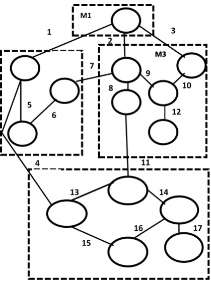
Definition1: (Modular system)
Figure 1. Example of modular system
In this example each modules represented by a dotted box, each module can have intra and intercommunication, intra modules communication represented by weighted edge with in the dotted box, inter modules communication represented by weighted edge between the dotted box
Definition 2: (System graph)
Given a modular system, MS, with n nodes partitioned into nM modules, its system graph, S, is all nodes in MS and all its edges, plus a disconnected node representing the system’s environment. Without loss of generality, index the environment node as i = 0, and the nodes in MS si= 1, ..., n. The system scope is defined by the given nodes and edges. We explicitly represent the unspecified environment by a single disconnected node. For measurement of coupling, we make a further abstraction, an intermodule-edges graph, which is a sub graph of S. Note that the properties of coupling focus on intermodule edges.
Definition 3 (Intermodule-edges graph)
Given a modular system, MS, and its system graph, S, its intermodule-edges graph, S*, consists of all nodes in S and all its intermodule edges. It is not necessary for subgraph S* to be a connected graph. For example, Figure 2 depicts the intermodule edges subgraph, S*, for the modular system in Figure 1.For measurement of cohesion, we make a further abstraction, an intramodule-edges graph, which is a subgraph of S. Note that the properties of cohesion focus on intramodule edges.
[image:6.595.314.536.69.321.2]Figure 2. Example inter-module edges graph
Figure 3. Example intra-module edges graph
Definition 4 (Intramodule-edges graph)
Given a modular system, MS, and its system graph, S, its intramodule-edges graph, so, consists of all nodes in S and all its intramodule edges. Similarly, it is not necessary for sub graph so to be a connected graph. For example, Figure3 depicts the intramodule edges sub graph, so, for the modular system in Figure 1. In order to analyze the patterns of relationships in s* or So, we label each node with the set of edges that are incident to it. Because the diagrams in software engineering, such as structure charts, identify each node with a component name, we choose an abstraction that maintains a
1
M1 0
2
3
4 M2
5
6
13
17
12
14 13
11
10 M4
14
16 15
9
9 6
8 7
5
M3 5
M3
8 10
12 4
2
11 1
2
3
4 M2
1 M1
12
14 13
11
10 M4
9 6
8 7
5
M3
5
M3
3
5
7
4
2
11 1
2
3
4 M2
5 6
11 1
M1 11
13
17
12
14 13
11
10 M4
14
16 15
9
9 6
8 7
5
M3
5
M3
8 10
12 3
5
7
0
[image:6.595.316.508.363.628.2]distinct identity for each relationship, rather than considering topology alone.
A convenient representation of the graph is a nodes x edges table where each cell indicates whether the node is an end point of the edge, or not. A nodes x edges table fully specifies an undirected graph. Each node’s label is encoded as the binary pattern of values in a row of the table. Table 3 shows the nodes x edges table corresponding to Figure 2. (Column pL(i) is e explained below.) The abstraction of a nodes x edges table is an instance of an object-predicate table, where nodes are objects and each predicate is of the form, “Is this node related to another node by this edge?” Object-predicate tables are useful for analysis of complex relationships among objects. Because object-predicate tables are suitable for relations in general, future research will extend this to more general measurement protocols. In summary, we begin with any protocol that results in a graphical abstraction of a modular system; we make a further abstraction to an intermodule-edges graph, S*, or an intramodule-edges graph, so; and Then translate that sub graph into a nodes x edges table.
[image:7.595.54.515.340.565.2]Table1.Example intermodule edges graph
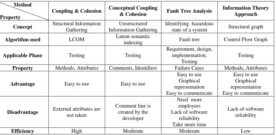
Table 2. Comparison between the methods for predicting the fault
Method
Property
Coupling & Cohesion Conceptual Coupling
& Cohesion Fault Tree Analysis
Information Theory Approach
Concept Structural Information
Gathering
Unstructured Information Gathering
Identifying hazardous
state of a system Structural graph
Algorithm used LCOM Latent semantic
indexing Fault tree Control Flow Graph
Applicable Phase Testing Testing
Requirement, design, implementation,
Testing
Testing
Property Methods, Attributes Comments, Identifiers Failure Cases Methods, Attributes
Advantage Easy to use Easy to use
Easy to use Graphical representation Easy to communicate
Easy to use Graphical representation Easy to communicate
Disadvantage External attributes are
not taken
Comment line is created by the
developer
Need more employers Lack of software
reliability Take more time
Lack of software reliability
Efficiency High Moderate Moderate Low
6. CONCLUSION
The above methods predict the faults in an object oriented system, it gives better quality, maintainability, and reusability. Table 2 shows the comparison between the various methodologies for prediction the fault. The fault prediction using coupling and cohesion uses attributes and methods of a class, it does not consider metrics like inheritance and data abstraction, In this method the fault predicted after the coding phase. The fault prediction using conceptual coupling and cohesion uses comments and identifiers. It was created by the developer for future references. If the developer does not aware comments will produce lack of measurement. In this method the fault predicted after the coding phase. In software fault tree analysis the fault predicted in requirement, design and implementation phases, but the fault predicted only using approximated failure cases. In information theory approach uses attributes and the relationship between the attributes. In
this method the fault predicted after the coding phase. The fault prediction before the coding phase is more effective and reduces the cost and time for testing.
7.References
[1]. Amol S.Dange ,Prof.Dr.S.D.Joshi ” Fault Prediction in Object Oriented System Using the Coupling and Cohesion of Classes, ” IJCSMS International Journal of Computer Science and Management Studies, Vol. 11, Issue 02,pp 48-51, Aug 2011.
[2]. AmolS.Dange , Prof.Dr.S.D.Joshi,” Fault Prediction in Object Oriented System usingthe Conceptual Coupling and Cohesion of Classes”, IJCST Vol. 2, Issue 3, September 2011.
Object-Oriented Systems,”IEEE TRANSACTIONSON SOFTWARE ENGINEERING, VOL.34, NO.2, pp 287-300, MARCH /APRIL2008.
[4]. Antoniol, G., Fiutem, R., and Cristoforetti, L., "Using Metrics to Identify Design Patterns in Object-Oriented Software", in Proc. of 5th IEEE METRICS'98, Bethesda, MD, pp. 23 - 34., 1998.
[5]. Antoniol.G, Canfora.G, Casazza.G, De Lucia.A, and Merlo.E, “Recovering Traceability Links between Code and Documentation,” IEEE Trans. Software Eng., vol. 28, no. 10, pp. 970-983, Oct. 2002.
[6]. Antoniol.G, Canfora.G, Casazza.G, and De Lucia.A, “Identifying the Starting Impact Set of a Maintenance and Reengineering”, Proc. Fourth European Conf. Software Maintenance, pp. 227-230.
[7]. Arisholm.E,Briand.L.C, and Foyen.A, “Dynamic Coupling Measurement for Object-Oriented Software,” IEEE Trans. Software Eng., vol. 30, no. 8, pp. 491-506, Aug. 2004.
[8]. Bansiya.J and Davis.C.G, “A Hierarchical Model for Object- Oriented Design Quality Assessment,” IEEE Trans. Software Eng., vol. 28, no. 1, pp. 4-17, Jan. 2002. [9]. Basili. V. R., Briand. L. C, and Melo. W. ”A validation
of object-oriented design metrics as quality indicators”.IEEE Transactions on Software Engineering, [10].Berry.M.W., “Large Scale Singular Value
Computations,” Int’lJ Supercomputer Applications, vol. 6, pp. 13-49, 1992.
[11].Bieman.J and Kang.B.K, “Cohesion and Reuse in an Object- Oriented System,” Proc. Symp. Software Reusability, pp. 259-262, Apr. 1995.
[12].Briand, L. C., Wüst, J., Daly, J. W., and Porter, V. D., "Exploring the relationship between design measures and software quality in object-oriented systems", Journal of System and Software, vol. 51, no. 3, pp. 245-273., 2000.
[13].Briand, L., Wust, J., and Louinis, H., "Using Coupling Measurement for Impact Analysis in OO Systems", in IEEE ICSM'99, pp. 475-482., 1999.
[14].Briand. L. C, Morasca.S, and Basili.V.R.,“Property based software engineering measurement”. IEEE Transactions on Software Engineering, 22( 1):68-85,Jan. 1996.
[15].Briand. L. C, Daly. J. W, and Wiist. J. K.“A unified framework for coupling measurement in object oriented systems”. IEEE Transactions on Software Engineering, 25(1):91-121, Jan. 1999.
[16].Briand. L. C, Daly. J. W, and Wiist. J. K. “A unified framework for cohesion measurement in object oriented systems”, In Proceedings of the Fourth International Symposium on Software Metrics, pages 43-53, Albuquerque, NM USA, Nov. 1997. IEEE Computer Society.
[17].Briand. L.C, Daly. J.W, and Wu¨ st. J., “A Unified Framework for Cohesion Measurement in Object-Oriented Systems,” Empirical Software Eng., vol. 3, no. 1, pp. 65-117, 1998.
[18].Briand. L.C, Daly. J.W, Porter. V, and Wu¨ st .V, “A Comprehensive Empirical Validation of Design Measures for Object-Oriented Systems”, Proc. Fifth IEEE Int’l Software Metrics Symp, pp. 43-53, Nov1998. [19].Briand. L.C, Morasca.s, and Basili.V.R, “Property-Based
Software Engineering Measurements,” IEEE Trans. Software Eng., vol. 22, no. 1, pp. 68-85, Jan. 1996. [20].Briand.L, Melo.W, and Wust.J, “Assessing the
Applicability of Fault- Proneness Models Across Object-Oriented Software Projects,” IEEE Trans. Software Eng., vol. 28, no. 7, pp. 706-720, July 2002.
[21].Chae .H.S. and Kwon.Y.R., “A cohesion measure for classes in object-oriented systems”. In Proceedings Fifth International Software Metrics Symposium, pages 158-166, Bethesda, MD USA,IEEE Computer Society, Nov. 1998.
[22].Dugan J.B., Sullivan, K. J., and D. Coppit, “Developing a High-Quality Software Tool for Fault Tree Analysis”, Transactions on Reliability, pp. 49-59 December 1999,. [23].Edward B. Allen, Taghi M. Khoshgoftaar, Ye
Chen,”Measuring Coupling and Cohesion of Software Modules: An Information-Theory Approach”,IEEE 2001. [24].El-Emam, K. and Melo, K., "The Prediction of Faulty Classes Using Object-Oriented Design Metrics", NRC/ERB-1064, vol. NRC 43609, 1999.
[25].Etzkorn.L and Delugach.H, “Towards a Semantic Metrics Suite for Object-Oriented Design,” Proc. 34th Int’l Conf. Technology of Object-Oriented Languages and Systems, pp. 71-80, July 2000.
[26].Ferenc.R, Besze´des.A, Tarkiainen.M, and Gyimo´ thy.T,“Columbus: Reverse Engineering Tool and Schema for C++,”Proc. 18th IEEE Int’l Conf. Software Maintenance, pp. 172-181, Oct.2002.
[27].Frances maryModugno, Nancy G. Leveson, Jon D. Reese, Kurt Partridge and Sean D. Sandys, “integrated Safety Analysis of Requirements Specifications'', IEEE International Symposium on Requirements Engineering, 1997.
[28].Gyimóthy, T., Ferenc, R., and Siket, I., "Empirical validation of OO metrics on open source software for fault prediction", TSE,vol.31/10,Oct' 2005.
[29].Harrison.R, Counsell.S.J, and Nithi.R.V.“ An evaluation of the MOOD set of object-oriented software metrics”. IEEE Transactions on Software Engineering, 24(6):491-496, June 1998.
[30].Harrison.R, Counsell.S.J, and Nithi.R.V.”Coupling metrics for object-oriented design”. In Proceedings Fifth International Software Metrics Symposium, pages 150-157, Bethesda, MD USA, IEEE Computer Society, Nov. 1998.
[31].Helmer, G., Slagell, M., Honavar, V., Miller, L. and Lutz, R., "A Software Fault Tree Approach to Requirement Analysis of an Intrusion Detection System" Symposium on Requirements Engineering for Information Security, March 5-6, 2001.
[33].Leveson, N. G. and P. R. Harvey, “Analyzing Software Safety”, IEEE Transactions on Software Engineering, Vol. SE-9, No. 5, pp. 569- 579, September 1983, [34].Leveson, Nancy G., Stephen S. Cha, Timothy J.
Shimeall, "Safety Verification of Ada Programs Using Software Fault Trees." IEEE Software. pp 48-59,July 1991
[35].Lutz, R. R., “Targeting Safety-Related Errors During Software Requirements Analysis,” Journal of Systems and Software, 34, 223-230, 1996.
[36].MassoodTowhidnejad Dolores R. Wallace Albert M. Gallo, Jr,”Validation of Object Oriented Software Design With Fault Tree Analysis”, Proceedings of the 28th Annual NASA Goddard Software Engineering Workshop (SEW’03) IEEE 2003.
[37].NUREG-0492, “Fault Tree Handbook”, U.S. Nuclear Regulatory Commission, January, 1981.
[38].Parnas.D. L. “On the criteria to be used in decomposing systems”. Communications of the ACM, 15(12):1053-1058, Dec. 1972.
[39].Poshyvanyk, D., Marcus, A., Ferenc, R., and Gyimóthy, T., "Using Information Retrieval based Coupling Measures for Impact Analysis", Empirical Software Engineering, vol. 14, no. 1, pp. 5-32., 2009.
[40].Quah, T.-S. andThwin, M. M. T., "Application of neural networks for software quality prediction using OO metrics", in ICSM'03,pp. 116-125.
[41].Shaw. M ,DeLine. R, Klein. D. V, Ross. T. L, Young. D. M, and Zelesnik.G.“ Abstractions for software architecture and tools to support them”. IEEE Transactionson Software Engineering, 21(4):314-335, Apr,1995.