Compression of Image using Enhanced EZW by Setting
Detail Retaining Pass Number
Isha Tyagi
Scholar of M.TechAshish Nautiyal
Scholar of M.TechMukesh Pathela
Assistant Professor
U.T.U. Dehradun (India) U.T.U. Dehradun (India) U.T.U. Dehradun (India)
ABSTRACT
For maintaining database system, the most important aspect is Compression. For which efficiency of compression system plays an important role. Now-a-days the optimization of bit stream is necessary to transfer the data in compressed manner. To achieve this objective the scheme used is embedded transmission. In embedded transmission the transmission of compressed low bit rate information is sent first then the higher bit rate information follows. The advantage of this scheme is if some information in the bit stream is not received, then using lower bit rate information corresponding to them can be decoded. Thus for these transmission scheme both the transmitting and encoding time are necessary. Thus for this objective we use Embedded zero tree wavelet (EZW) encoding technique for the compression & embedded transmission of images.
The main objective of this paper is to implement & show how to improve EZW coding with reduced & improved execution time. Therefore by assuming most of the coefficients value present in the decomposed subband to be low and near to zero, present coding can be improved, as there is no need to check them again and again for significance.
Keywords
Discrete wavelet transform, image compressing, Embedded Zero-Tree Wavelet (EZW)
1.
INTRODUCTION
The objective of this paper is to improve the Embedded Zero-Tree Wavelet compression algorithm as much as possible, including the complexities of time and space.
The problem is useful in many applications like Biometrics, which consists of images of faces, fingerprints etc, in Biomedical Imaging for diagnosis of disease, and in some general imaging applications like image browsing, photography, multimedia, etc. It is also very important as in this the transmission of information is according to the prioritization given to the bit stream.
In this paper our aim is to highlight the proposed EZW coding scheme to reduce the execution time by 2 sec and with this compression ratio also reduced by 2%.
2.
EMBEDDED ZERO TREE WAVELET
CODING (EZW)
Jerome M. Shapiro gives the concept of Embedded Zero Tree Wavelet Encoding, in his IEEE transaction. The most widely
and one such existing technology is Video codec based on EZW e.g. MPEG-4. In embedded coding the linear bits of information are transmitted first than the higher bits follows. Which means the information of the lower importance is transmitted first; later the information of higher importance is transmitted [5]. That adds itself to the earlier transmitted information. With this kind of prioritization, effective transmission scheme is generated.
In the embedded coding the lower bit rate codes are embedded at the beginning of the bit stream. As according to prioritization bits are ordered accordingly. An encoder can terminate the encoding process at any point using an embedded code. Whole encoding process is monitored with the help of some target parameter, such as target count. The encoding stops after meeting its target. Similarly with the help of bit stream, decoder can decode the lower rate encodings at any point and reconstruct the data corresponding to it.
2.1
Features of Embedded Zero Tree
Encoding
2.1.1
Parent-child relationship
The parent child relationship is known as ancestor-descendant relationship. This is based on hierarchical orientation of levels. It simply means that a pixel in a coarser scale represents four pixels in the finer scale. The base of EZW is the parent –child relationship in wavelet transform.
2.1.2
Concept of Zero trees in EZW
It states that “If the root of wavelet coefficient tree and all its corresponding descendants are below the given threshold then the tree is said to be zero tree and the corresponding root is known as zero tree root (ZTR).”
2.1.3
Concept of Isolated zero in EZW
It states that “If the root of wavelet coefficient tree is less than the given threshold at any level but if one or more of its descendants are greater than the given threshold then the root is said to be an Isolated zero root.” But in this case, it should be noticed that only the root is encoded as isolated zero in EZW not the entire tree.
2.1.4
Concept of positive -negative significant in
EZW
3.
WAVELET AND
MULTI-RESOLUTION THEORY
3.1
History of Wavelet
Basically wavelets are considered as mathematical function which cut up data into different frequency components. Wavelet applications include image compression, turbulence, human vision, radar and earthquake prediction [1]. Jean Martlet an engineer, described wavelets of constant shape which latterly known as Martlet wavelets. He also produced the proof that reconstruction of wave could be possible from their wavelet decomposition. Then in1986 student of Meyer, Stephen Mallat, introduced the concept of multi resolution which is the keystone to wavelet theory. Ingrid Daubechies brought the final revolution in the area of wavelets in 1987. She discovered a whole new class of wavelets not only orthogonal but can be implemented using simple and short filters. Latterly combining the work of Daubechies and Mallat, a simple orthogonal transform is evolved which could be calculated on modern digital computers.
3.2
Orthogonal Functions
In the field of signal processing two functions are said to orthogonal if following relationship exists between them.
(1)
Where and are two functions. Some orthogonal functions are sine and cosine waves in the same interval of time.
3.3
Dyadic Sampling
[image:2.595.60.303.480.567.2]Sampling of alternate values of signal is called dyadic sampling, as its name “dia” means two. Dyadic sampling is of two type i.e. dyadic down-sampling and dyadic up-sampling. In both types where alternate terms of signal are dropped, in other zero padding is done alternatively. Dyadic up-sampling is shown in Fig. 1.
Fig. 1. (a) Signal Components (b) Up-sampled signal
components.
3.4
Concept of Filter Banks and
Functions
According to I. Daubechies [3] implementation of wavelet transform can be done by using discrete filters. In multi-resolution approach it cannot be done by using a single and a specific filter. We need to have a filter with some parameters for a particular region and different one of other region. So the concept of filter bank came into existence. Even wavelet function and corresponding scaling function are generated from these filter banks.
From equation 1relationship between and can be given as,
(2)
(3)
After applying specific constraints, to use these filter banks for designing of wavelet first coefficients are obtained.
4.
DISCRETE WAVELET TRANSFORM
4.1
Wavelet coding of Images
Images are 2-D signals. The wavelet coding of a 2-D signals i.e. image, is done similarly as in 1-D signals. To obtain the approximation and details of images the discrete wavelet transform is applied both along rows and columns [4].
4.2
Image Decomposition
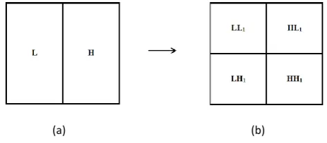
For the image decomposition, the image carries information varying along two dimensions. For the extraction of approximation and detail coefficient is required from both the directions. To achieve this purpose first low pass filter and high pass filter are moved over the rows of image and then the result is decimated by a factor of 2. By this the wavelet decomposition subband is divided into two parts. One subband contains the information of low frequency i.e. approximation of rows and other contains high frequency information i.e. detail along the rows. Same procedure is repeated for columns. , is the approximation where remaining three subbands are of detail as horizontal ( ), vertical ( ) or diagonal ( ). This operation is explained as below.
Fig. 2 shows the construction of subband after filtering and downsampling operation. While in Fig. 3 same operation is shown with the help of block diagram. In Fig. 4 two level of operation is performed where same operation is repeated for each subband in level one. For a practical image it can be done on several stages of operation, explained in Fig. 1, where subbands are decomposed into other subbands.
4.3
Image Reconstruction
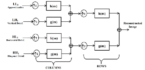
The image reconstruction from the decomposed wavelet coefficient band is done by passing it to the synthesis filter banks which will be followed dyadic up-sampling. The image reconstruction of image is just opposite of the decomposition process and is also known as Inverse Discrete Wavelet Transform (IDWT). Reconstruction operation is shown in Fig. 5, where block diagram is represented.
Fig. 2. Subband after filtering and downsampling (a) over rows and (b) over both rows and columns.
(a) (b)
[image:2.595.323.560.582.686.2]Fig. 3. One-stage 2-D wavelet decomposition of image.
Fig. 4. Two level wavelet decomposition subband.
Fig. 5. Two-stage 2-D wavelet reconstruction of image.
5.
DESCENDENT COEFFICIENT
SCANNING AND ENCODING
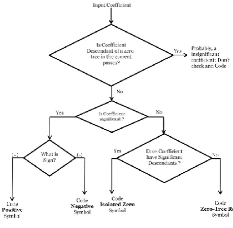
Embedded Zero Tree Wavelet consists of four symbols which actually represents it. They are
A zero tree root
An isolated zero
A significant positive coefficient
A significant negative coefficient
In each pass of embedded zero tree wavelet coding, each coefficient has to pass through a scanning process, where it is scanned for all the four symbols. In each iterative pass of the compression algorithm it is done systematically. The major part of the execution time in the dominant pass of the compression algorithm is consumed while scanning the tree of insignificant coefficient for zero tree or for insignificant zeroes.
As per the structure of tree if a particular frequency band’s coefficient is insignificant, then all its descendants will fall to insignificant category. In the decomposed subband structure most of the detail subbands are dark at all the levels, which apparently clarify that most of the coefficient values in that detail subband are near to zero. Therefore they may not become significant even in successive iterative passes, where there is reduction by a factor of 2 in the threshold, as they are near to zero “[5]”.
By not scanning the descendants of zero tree of the previous passes in the successive passes as we can consider that most of the values are near to zero and will become insignificant at all, even when the remarkable reduction in threshold value is made, a significant improvement can be made in the execution time of the existing compression algorithm. The purpose to choose descendants is they will always lie in the detail subband, where as zero tree root may also lie in the approximation subband.
The base of the proposed work is formed by the above stated concept. An improved algorithm will be proposed by altering the dominant pass of EZW. It is done on the main basis of improved execution time.
5.1
Coding scheme A
The coding scheme A is actually based on the previous statement to improve the execution time in zero tree wavelet. Some changes will be made in the dominant pass of the algorithm, where approximation and quantization done in the subordinate pass remains the same.
Execution time of the algorithms in the dominant pass is greatly improved. This is because of the ignorance of coefficients, in any iterative pass becomes descendants of zero tree. Thus only for the first iterative pass the whole decomposed subband is scanned. There is large number of descendants, since large number of zero trees is encountered. Therefore in the next passes these descendants are not scanned again assuming that all of them have almost zero magnitude, thus improving the execution time.
The main drawback in coding scheme A is the detail subband in the wavelet decomposition subband contains edges with coefficient greater than zero magnitude. As in the initial passes the threshold is high and all the edges and other details have coefficient values less than the threshold encoded may come under the descendant of zero tree roots. Thus they will not become significant as they will not be scanned in any of the successive passes, even if the threshold is lowered down. Thus on the compromise of losing some details, coding scheme A improves the execution time.
5.2
Coding Scheme B
[image:3.595.56.306.509.630.2]evaluated for it being significant. The restriction is made on the descendant of current pass.
In this coding scheme the quality of image is maintained even after the compression of the image but there is not much improvement in the dominant pass execution time.
5.3
Improved Coding Scheme C
[image:4.595.322.559.95.326.2]Both the advantages and effects of coding scheme A and B are incorporated in the coding scheme C .In this coding scheme the scanning is not only restricted to the descendant of previous passes. Therefore the encoding of the edge and detail information in the detail subband is done and then the coefficient of the detail subband is done and then the coefficient of the detail subband becomes significant. Thus by lowering the threshold in successive passes they are brought out descendants. Now they are being checked for their significance and will be encoded if found so. After a certain point we can assume that all the coefficients which contain information about the edges have been encoded as they are no more descendants of zero tree, they are significant now. Now it is believed that majority of zero tree are descendants which are near to zero magnitude and will not be significant in next passes. From this only the remaining edges and detail information may become insignificant in the further passes which will be checked by the isolated zeroes.
[image:4.595.55.301.364.591.2]Fig. 6. Flow chart of coding scheme A.
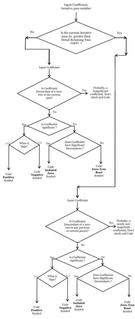
Fig. 7. Flow chart of coding scheme B.
This is done with the correct and appropriate ease of both the coding scheme A and B. The coding scheme B is applied up till a number of certain passes. After this coding scheme A is executed when it is believed that majority of zero trees contain descendants, as they have magnitude near to zero. As a result in successive passes scanning of the previous passes descendants is skipped.
Detail retaining passes is the iterative pass at which we change the coding scheme.
Therefore the coding scheme C is the most efficient and unique way to encode the image in the dominant pass by giving the Detail Retaining Pass (DRP) number [7]. In this threshold is being set above the edge coefficient existence. At the end of both the sub branches the symbols kept for encoding the different properties of subband are same. Hence there is no increase in the cost due to increase in the number of symbols. The coding scheme is better way to encode the image in minimum time.
6.
AN EXAMPLE AND RESULT
pass, the quantized coefficients are arranged according to subbands. For the reconstruction of the image using a defined wavelet, inverse discrete wavelet transform is obtained. After obtaining the image various parameters are calculated.
For the operation we use gray scale image of “Elaine” of size 512x512.
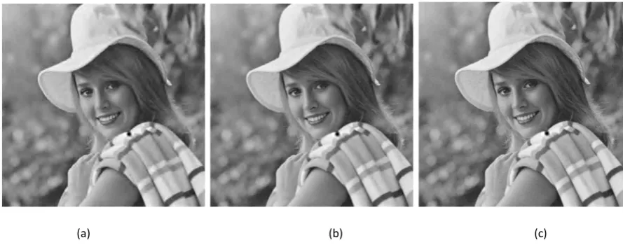
Now the coding scheme A is applied over the gray scale image of Pirate. It is done for 10 passes and various parameters are recorded including the dominant pass execution time. After applying coding scheme A, the total execution time of 10 dominant passes in sec. is 43.1128 sec. without estimating subordinate pass time. In Figure 9 result of 6, 7 and 8 passes of coding scheme A is shown in (a), (b) and (c) respectively.
[image:5.595.316.541.71.601.2]After this scheme A, we apply coding scheme B for the same Elaine image for 10 passes and again various parameters are recorded including the dominant pass execution time. Now the total execution time of 10 dominant passes in sec. is 55.1874 sec. without estimating subordinate pass time. In Figure 10 result of 6, 7 and 8 passes of coding scheme B is shown in (a), (b) and (c) respectively.
(a) (b) (c)
Fig. 9. Decoded Images of “Elaine” after encoding it Coding Scheme A for (a) 6 passes, (b) 7 passes and (c) 8 passes
(a) (b) (c)
Fig. 10. Decoded Images of “Elaine” after encoding it by Coding Scheme B for (a) 6 passes, (b) 7 passes and (c) 8 passes
Lastly coding scheme C is applied on that gray scale Elaine image for 10 passes and various parameters are recorded. In this scheme we include the execution time by setting the detail retaining pass number taking them different each time.
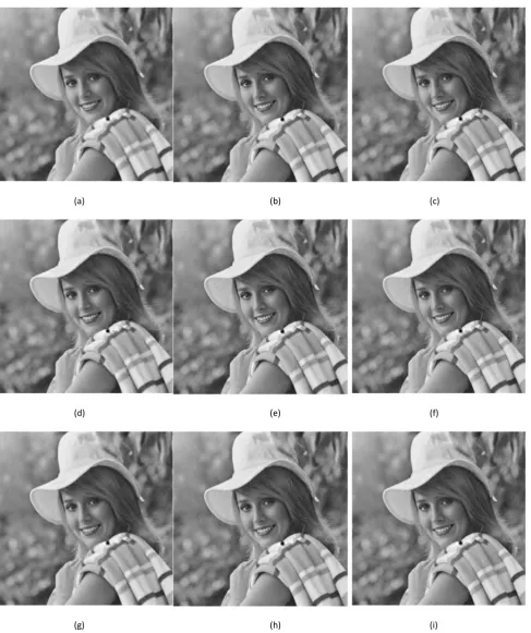
For DRP=3, the total execution time of 10 dominant passes in sec. is 52.6280 sec. without estimating subordinate pass time. It is shown for 6, 7 and 8 passes of coding scheme C in Fig. 11 (a), (b) and (c) respectively.
For DRP=4, the total execution time of 10 dominant passes in sec. is 53.5764 sec. without estimating subordinate pass time. It is shown for 6, 7 and 8 passes of coding scheme C in Fig. 11 (d), (e) and (f) respectively.
For DRP=5, the total execution time of 10 dominant passes in sec. is 53.4496 sec. without estimating subordinate pass time.
It is shown for 6, 7 and 8 passes of coding scheme C in Fig. 11 (g), (h) and (i) respectively.
For the analysis purpose the execution time of dominant pass has been recorded up to different number of passes. The effect of changing the algorithm for the improvement in the execution time is analyzed with respect to the image quality obtains thereby.
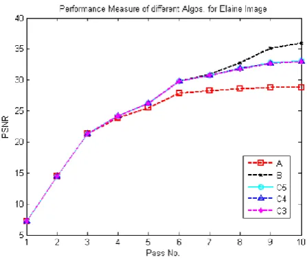
The PSNR of Elaine image after decoding at subordinate pass of different algorithm is obtained and has been plotted in the Fig. 12 for different iterative passes.
From the table 1, it is clear that in all 6 iterative passes the coding scheme C saves around a second for different DRP as compared to idle coding scheme B.
[image:6.595.75.520.273.448.2](a) (b) (c)
(d) (e) (f)
[image:7.595.58.546.67.649.2](g) (h) (i)
Fig. 11. Decoded image of “Elaine” after encoding it by coding scheme C by setting DRP=3 for (a) 6 passes, (b) 7 passes and
TABLE 1. Execution time of dominant passes recorded up till different iterative passes.
Scheme →
A B C,
DRP=3 C,
DRP=4 C,
DRP=5
Pass 6 33.7419 40.5758 39.7179 39.1432 40.0830
Pass 7 36.2459 44.3879 43.4798 43.1661 43.4928
Pass 8 39.2664 49.3753 46.8478 46.6384 47.2191
Pass 9 41.2356 52.4219 49.5453 49.6282 50.7656
Pass 10 43.1128 55.1874 52.6280 53.5764 53.4496
From plot of PSNR in Fig. 12 it can be seen that at 7 iterative pass there is a little fall in coding scheme C as compared to coding scheme B. and this variation is less than 1 dB. In the 8th iterative pass there is a difference of 2 db in coding algorithm C with DRP=3 as compared with coding algorithm B. and the difference of 1dB is noted at DRP=5 but the improvement is less. The threshold become very less at 8th, 9th and 10th iterative pass.
Therefore for the given image coding scheme C is best till 7 iterative passes as it gives improvement of 2 sec. in execution time up to 7 iterative passes. And improvement of 3 sec. can be noticed in the execution time in collective 8 iterative passes but the fall in PSNR is more than assumed. At pass 9 and above coding scheme is preferred as it gives high PSNR at low threshold values.
7.
CONCLUSION
This paper presents the unique way by introducing the execution time of dominant pass in the algorithm to improve the encoding time in Embedded Zero-Tree Wavelet (EZW) coding. In the paper it has been shown that the proposed coding scheme C saves 2 seconds or more in successive execution of 7 dominant passes, without estimating the subordinate passes. Improvement in the compression ratio is also achieved by 2%. No compromise from the side of subordinate passes is included, as no changes have been made in them. The PSNR obtained from the decoded image of coding scheme C is almost remains the same as after EZW coding.
Fig. 12. PSNR plot of uncompressed decoded “Elaine” Image at different iterative for different coding scheme
8.
REFERENCES
[1] K.P. Soman; K.I. Ramchandran; “Insight into Wavelets – From Theory to Practice”, Prentice Hall of India, Second Edition, pp. 6-9, 2005 (references)
[2] S. Mallat; “A theory for multiresolution signal decomposition: The wavelet representation,” IEEE Trans. Patr. Anal. Machine Intell., vol. 11, no. 7, pp. 674-693, July 1989.
[3] Daubechies; Ten Lectures on Wavelets, SIAM, 1992
[4] M. Antonini, et.al.: “Image Coding Using Wavelet Transforms” IEEE Trans. Image Processing, vol. 1, no. 2, pp 205-220, April 1992
[5] J.M. Shapiro; “Embedded Image Coding Using Zerotrees of Wavelet Coefficients” IEEE Trans. on Signal Processing, vol. 41, issue 12, pp 3445-3462, 1993
[6] Amir Averbuch, et.al.: “Image Compression Using Wavelet Transform and Multiresolution Decomposition”, IEEE Trans. Image Processing; vol. 5, no. 1, pp 4-15, January 1996
[7] L. Xuhong; et.al: “Improved Image Coding Algorithm Based on Embedded Zerotree”; Eighth ACIS Int. Conf. on Software Engineering, Artificial Intelligence, Networking, and Parallel/Distributed Computing , vol. 2, pp. 189-192, 2007