Comparison of Pole Placement & Pole Zero Cancellation
Method for Tuning PID Controller of A Digital Excitation
Control System
Deepak M.Sajnekar
*, Dr. S.B.Deshpande
**, Dr. R.M.Mohril
****
PhD scholar YCCE, Hingna Road, Nagpur
**
Principal, GWCET, Nagpur
***
Prof (Electrical Engg), YCCE, Nagpur
Abstract- Modern Digital Excitation control system now started utilizing the power flexibility and cost advantage of Microprocessors for control. Many rotary excitation control system are still using analog type of Automatic voltage regulator which now started to replace with the digital Automatic voltage regulator. Modern Digital automatic voltage regulator is provided with PID controller in the forward path and tuning of PID controller is a challenging task. This paper discusses two methods of tuning PID controller i.e. Pole placement method and pole zero cancellation method. GUI (Graphical user interface) prepared for both the methods on the platform of MATLAB. Using this GUI performance results and time required for tuning for both the methods are compared.
Index Terms- Digital excitation system, Automatic voltage regulator, Pole placement method, Pole Zero cancellation method
I. INTRODUCTION
he term “excitation control system” refers to the entire control system including the synchronous machine and power system as well as the excitation system.[4]
Reliability of the excitation system has become an issue, especially where many of the generation plants may be critical to the internal processes used for manufacturing. A modern static excitation system is often the favored solution for old rotary excitation system since it has problems associated with it which are primarily mechanical.
Normal Industrial practice is to use static excitation system for generators requiring excitation current of 100A to 10000A and to use rotary excitation system for generators requiring excitation current of 1A to 200A .
Modern excitation systems are beginning to utilize the power, flexibility, and the cost advantage of digital electronics. There are a large number of aging excitation systems with rotary exciters in need of upgrading there are also cases where the rotary exciters are in good condition but need upgrading of the controls. In such cases only analog voltage regulator needs to be replaced with modern digital automatic voltage regulator.[3] In the recent practice of the consultants, offering services in the field of maintaining & improving performance of excitation control system replacing Analog AVR’s of rotary excitation systems with modern digital AVR’s.
For the effective tuning of the rotary excitation system involving modern digital AVR there is need for models that accurately simulate the operation of excitation control systems during system disturbances in absence of precise data. It is because precise data for the old rotary excitation is generally not available.
There are many microprocessor based AVR has been discussed in the literature, These works on two types of algorithm i.e Arithmetic based algorithm and Logic based algorithm . Like Fuzzy logic controllers, ANN controllers etc.[10,11,12,13,14]
The success of the logic based algorithm based on the availability of the systems data like exciter time constant , generator time constant , Loop gain etc.
Two popular methods available for tuning of PID controller are Pole Placement method and Pole zero cancellation method For Modern digital excitation control system ,if the algorithm for both the methods are prepared using arithmetic approach then the model resulted for the digital excitation control system will work satisfactorily even in the absence of precise data of the system.[15]
GUI (Graphical User Interface) for both the methods have been prepared on the MATLAB platform using GUIDE function Performance of the tuned Modern digital AVR by using both the method i.e. Pole placement method and Pole Zero cancellation method have been compared
II. EXCITATION CONTROL SYSTEM
The term “excitation control system” refers to the entire control system including the synchronous machine and power system as well as the excitation system. [4] . Block diagram is shown in fig 1.
Fig .1. Block Diagram of the excitation control system
2.1. Types of excitation system.
Broadly two types of excitation systems are only recognized in the industry.
1. Static Excitation system. 2. Rotary excitation system.
These are further classified depending on following.
Depending on supply given to AVR (Automatic voltage Regulator) .
a) Self excited excitation system
For this type of system automatic voltage regulator does not require supply from the external sources like PMG (permanent magnet generator) or battery, it takes supply directly from the output of the main generator.
b) Separately excited excitation system
For this type of system automatic voltage regulator requires supply from the external sources like PMG (permanent magnet generator) or battery,
Depending on the technology used for making AVR.
a) Analog Excitation system.
This type of excitation system uses Analog IC’S like OP AMP
b) Digital Excitation system.
This type of excitation system uses chips like DSP or Microprocessor
III. TUNING OF PID CONTROLLERS
There are two popular methods of tuning PID controllers Pole Placement Method and Pole Zero Cancellation Method
3.1. Pole placement method.
This needs to determine Transfer function model of the exciter with generator G(s).Then determine transfer function H(s) of AVR with PID whose gains are unknown. Using characteristic equation G(s) H(s) = -1. Assume S = (a + jb) and equate real and imaginary terms we get two equations. Third equation is obtained by putting S= c .Now there will be three equations and three unknowns (KP KI and KD) we can find KP KI and KD. Using
this known values of KP KI and KD. We will find TF of system.
Using this T.F. unit step voltage response, open loop frequency response, closed loop frequency response and root locus of the system will be obtained using GUI based on MATLAB.
This process will be repeated till we get desired transient response specifications.
Basically above process involve the placement of two dominant poles which are near the imaginary axis and belongs to generator and controller are made complex conjugate that makes response of the system underdamped.
The third pole of the exciter is kept a real pole and is placed far away from the imaginary axis so that it should not affect the natural mode of the voltage response.
The closed loop transfer function also involves The placement needs some trial and error in order to reduce the effect zero on the dynamic response of the performance..
3.2. Pole Zero cancellation method.
The PID equation can be written in this form:
When this form is used it is easy to determine the closed loop transfer function.
If
and
Then
This can be very useful to remove unstable poles.
IV. MODELS DESIGNED FOR AVR USING BOTH THE METHODS.
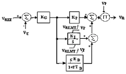
IEEE Std. 421.5 Type AC5A - Simplified Rotating Rectifier Excitation System Representation has been considered which then simplified to a Modern Digital AVR. The simplified model of the digital AVR is shown in fig 2.
VREF is the generator reference voltage
Vc is sensed voltage VRLMT is max field forcing
[image:2.612.335.546.532.656.2]Vp power input voltage VR is Regulator output voltage
4.1: System specification
The system considered for the analysis has following specification
500 KVA Diesel generator set (CUMMINS POWERICA)
Type of ac generator : brushless ac generator (STAMFORD make , Model : HCI544D1)
Type Of Excitation System : Self excited rotating rectifier type excitation system.
Type of AVR : Analog type ( AS 440)
Only generator time constant tg = 2.2 sec is available Exciter time constant is not available therefore it is
considered as te = tg/6 sec
The generator under control is fed by a rotary exciter. The plant transfer function G(s) is given as
where
tg = the generator open-circuit time-constant te = the exciter open-circuit time-constant.
The continuous-time PID controller model can be written as
4.1 Model of the AVR using pole placement method.
The characteristic equation of the resulting closed-loop system is expressed in different forms as follows.
It is desired that
The closed-loop system be dominantly second order. The dominant closed-loop poles (s = a & jb) are therefore selected from the peak overshoot and settling time specifications. The third pole is selected to be real (s =c) and in the far left-half plane, so that the closed-loop system is dominantly second-order. Substituting s=a+jb in the characteristic equation, and equating the real and imaginary parts, results in two equations. The third equation is obtained by substituting S = C in equation. The three unknown values (Kp , KI , KD) are then obtained from the three
equations. A word of caution regarding the system zeroes is in order. The PID controller designed via pole placement method will force the closed loop poles to lie at the selected locations. The placement of the poles is achieved via appropriate choice of the controller settings ( KP, KI, KD ). These controller settings
give rise to two zeroes. The locations of the zeroes of the controller may be real or may even turn out to be a complex conjugate pair. The controller zeroes are not only the open-loop
zeroes but also the closed-loop zeroes. Since the zeroes do affect the transient response some experienced engineering adjustment required in the design.
4.2 Model of the AVR using pole Zero cancellation method. The characteristic equation of the resulting closed-loop system can be written as
For the pole zero cancellation , we set
=
Thus the transfer function gets reduced to
The closed loop transfer function then becomes
The time response to a unit step input is as follows
If tr is the specified rise time which is defined as the time
required for the response to rise from 10% - 90% of its final value, the value of KD is obtained by
It can be seen that KD depends on the plant parameters and
the desired rise time. Once we establish KD we can calculate KI
and KP from the equation discussed above
At first, the idea of pole-zero cancellation might seem academic since the exact pole-zero cancellation is virtually impossible.
V. GRAPHICAL USER INTERFACE (GUI)
Graphical user interface prepared for Pole placement method which is also called direct design approach and pole Zero cancellation method is prepared in the MATLAB platform using GUIDE function
5.1 Acceptable values of Perfomance Index As per IEEE std • Rise time = 0.15 to 2.55 sec
• Overshoot = 0 to 15% • Settling time = 0.2 to 10 sec • Bandwidth = 0.3 to 12 Hz
5.2: GUI For Tuning PID Controller By Pole Placement Method
GUI (Graphical user interface) to be used for pole placement method is shown in fig 3
Fig3 . GUI for DECS using Pole Placement method
Pole placement method applied for rotary excitation system of 500KVA Diesel Generator set whose generator time constant is only known
The desired performance index would be • Overshoot should be less than 15% • Settling time should be below 1.5sec • Bandwidth should be upto 12 Hz
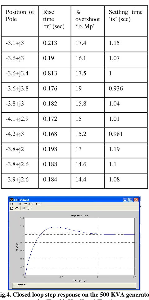
Table 1. shows that the desired location of poles which meets desired performances indexes are at -3.9+ j2.6. GUI gives values of KP =33, KI=47 and KD=6 for this location.
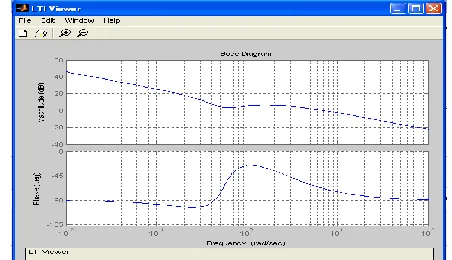
Fig 4, shows the closed loop unit step response with settling time = 1.5sec and overshoot is 14.2%, rise time = 0.188sec
Table 1. Search for better pole placement
Position of Pole
Rise time ‘tr’ (sec)
% overshoot ‘% Mp’
Settling time ‘ts’ (sec)
-3.1+j3 0.213 17.4 1.15
-3.6+j3 0.19 16.1 1.07
-3.6+j3.4 0.813 17.5 1
-3.6+j3.8 0.176 19 0.936
-3.8+j3 0.182 15.8 1.04
-4.1+j2.9 0.172 15 1.01
-4.2+j3 0.168 15.2 0.981
-3.8+j2 0.198 13 1.19
-3.8+j2.6 0.188 14.6 1.1
[image:4.612.325.565.72.553.2]-3.9+j2.6 0.184 14.4 1.08
Fig.4. Closed loop step response on the 500 KVA generator for KP =33, KI=47 and KD=6
Fig 5. Open Loop frequency response on the 500 KVA generator for KP =33, KI=47 and KD=6
Fig.6. Closed Loop frequency response on the 500 KVA generator for KP =33, KI=47 and KD=6
Fig.7. Root locus of the controller designed by pole placement method.
Closed loop frequency response Fig6, shows the phase lag of -61.1 degree at -3db. The decibel rise prior to roll off indicates that during step voltage test voltage overshoot is noted . The bandwidth is 9.55Hz
Root locus of the controller designed by pole placement method is shown in fig 7 confirms that in spite of oscillations system will be stable.
There is again a scope for a commissioning engineer to perform trial & error and also implement his field experience for making a system more stable. This is for making placement of
zeroes in such a way that transient response is reduced by certain amount.
5.3: GUI for Pole Zero cancellation Method
[image:5.612.59.278.236.400.2]GUI (Graphical user interface) to be used for pole placement method is shown in fig 8
Fig.8. GUI for DECS using Pole Zero cancellation method
Fig.9. Closed loop step response on the 500 KVA generator for KP =30, KI= 11 and KD= 9
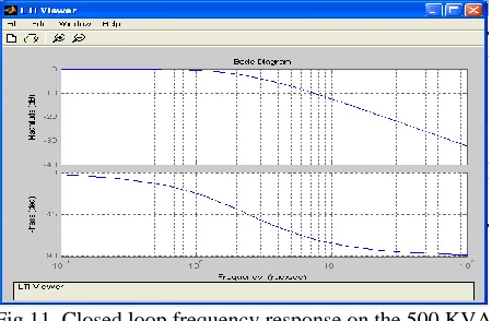
[image:5.612.333.554.312.440.2] [image:5.612.59.277.430.582.2] [image:5.612.330.556.478.608.2]Fig.11. Closed loop frequency response on the 500 KVA generator for KP =30, KI= 11 and KD= 9
Closed loop step response of the controller as shown in Fig9. is as per the desired rise time of 0.188 sec, settling time is 0.335 sec and almost no overshoot
Fig 10 .Open loop frequency response Shows that at 0 db, crossover frequency is 37 Hz the phase lag is -85.7 degree (less than what We got using pole placement method-87.5 degree) Fig11.Closed loop frequency response shows the phase lag of -44.9 degree at -3db. There is no decibel rise prior to roll off
Confirms that during step voltage test no voltage overshoot noted The bandwidth is 11.6Hz (more than that we got using pole
[image:6.612.59.278.369.514.2]placement method 9.55Hz)
Fig 12. Root locus of the controller designed by pole Zero cancellation method
Fig 12.shows that the locus is on the real axis confirms that there will be no oscillation and hence system is more stable.
VI. COMPARISON OF PERFORMANCE
The performance of the controller designed using pole placement method and pole Zero cancellation method has been compared and presented in Table.2.
Table,2. Comparison of Performance
Methods/ Performance Index
Pole Placement Method
Pole Zero Cancellation Method
Rise Time(sec) 0.188 0,188 (desired)
Settling Time(sec)
1.1 0.335
% Overshoot 14.2 0
Bandwidth (rad/sec)
9.55 11.6
Degree of phase lag
61.1 44.9
VII. CONCLUSION
The comparison for pole-placement and the pole–zero cancellation methods for tuning PID controllers for digital excitation systems have been presented with the help of GUI using MATLAB. The Pole zer cancellation method requires less time for tuning PID gains therefore quick commissioning can be accomplished with excellent performance results.
REFERENCES
[1] R. C. Schaefer, “Steam turbine generator excitation system modernization,” in Proc. IEEE Pulp and Paper Industry Tech. Conf., 1995, pp. 194–204. [2] R. C. Schaefer, “Application of static excitation systems for rotating exciter
replacement,” in Proc. IEEE Pulp and Paper Industry Tech. Conf., 1997, pp. 199–208.
[3] K. Kim, A. Godhwani, M. J. Basler, and T.W. Eberly, “Commissioning experience with a modern digital excitation system,” IEEE Trans. Energy Convers., vol. 13, no. 2, pp. 183–187, Jun. 1998.
[4] IEEE Guide for Identification, Testing, and Evaluation of the Dynamic Performance of Excitation Control Systems, IEEE Std 421.2-1990. [5] R. C. Schaefer, “Voltage versus var/power factor regulation on hydro
generators,” presented at the IEEE PSRC, 1993.
[6] IEEE Guide For Preparation Of Specification For Excitation Systems, IEEE Std 421.4 1990.
[7] C S Hoong, S Taib MIEEE, K S Rao and I Daut “Development of Automatic Voltage Regulator for Synchronous Generator” National Power & Energy Conference (PECon) 2004 Proceedings, Kuala Lumpur, Malaysia
[8] A. Godhwani, M. J. Basler. “A Digital Excitation Controll System For Use On Brushless Excited Synchronous Generators” IEEE Transactions on
Energy Conversion, Vol. 11, No. 3, September 1996
[9] Abul R. Hasan, A.H.M. Sadrul Ula, “Design and Implementation of a Fuzzy Controller Based Automatic Voltage Regulator for a Synchronous Generator” IEEE Transactions on Energy Conversion, Vol. 9, No. 3, September 1994
[10] Longquan Xu ,Jianhua Wei, Cong Peng “Backstepping Control Of Digital Excitation Systems Based On Neural Network” 978-1-4244-1706-3/08/$25.00 ©2008 IEEE.
[12] Yuanchu Cheng, Zhuoyu Jiang, Dehong Xu, and Yan Liu “Nonlinear Analytical Fuzzy Logic Control of Generator Excitation” DRPT2008 6-9 April 2008 Nanjing China
[13] Huilan Jiang, Xuegong Yin ,Yunshan Chen, Dongwei Li “Optimal Excitation Control of Synchronous Generator Based on Adaptive Ants Colony Algorithm” Third International Conference on Natural Computation (ICNC 2007) 0-7695-2875-9/07 $25.00 © 2007
[14] Lingyan Hu, Yong Xin, Jie Peng, Helei Wu “The Excitation Controller of Synchronous Generator Employing PID and Fuzzy Integrated Algorithm Based on S3C2410A” 2008 ISECS International Colloquium on Computing, Communication, Control, and Management
[15] Kiyong Kim, Richard C. Schaefer. “Tuning a PID Controller for a Digital Excitation Control System” IEEE Transactions On Industry Applications, Vol. 41, No. 2, March/April 2005
AUTHORS
First Author – Deepak M Sajnekar. PhD Scholar (Electrical Engineering). Yeshwantrao chavan collegeof Engineering Nagpur , [email protected]
Second Author – Sadanand B Deshpande PhD (Electrical Engineering) Govinrao Wanjari college of Engineering & Technology Nagpur., [email protected]