The analysis of FEM simulation of the effects produced
by the pulse load on the bridge in order to identify
vibration propagation from the traffic
Ing. Katarína Demeterová*, Ing. Daniel Papán, PhD.** *
Department of Structural Mechanics, Faculty of Civil Engineering, University of Žilina
Abstract- The technical seismicity is perceived as a negative effect on the environment, buildings and constructions. We mean that seismic vibrations are induced by the force impulse, stochastic process, and artificial source. [1]. In Slovak republic, there is the impact of vibrations on building structures rated in Eurocode 8, however, STN 73 0036 is dealing directly with the technical seismicity. Simultaneously, this norm classifies bridges into the group “U”, therefore into the group that is significant in terms of the technical seismicity. Using the FEM simulations and comparison in similar conditions is important for the analysis of these cases, due to short norm rating of this issue.
Index Terms- FEM simulation, force impulse, technical norm, technical seismicity
I. INTRODUCTION
his article is about the analysis of the FEM simulation of the effects produced by the force impulse on the bridge as the real construction – M5973 Brodno – Žilina. The roadway bridge is built from concrete and it has got three spans. The cross section of the bridge is one – chamber beam.
The bridge was modeled in two versions, the first one as 2D FEM model and the second one as 3D FEM model. The first custom shape of vibration and the first custom frequency were detected by the FEM calculation and they were also compared in both versions.
The effect of technical seismicity conforms to the effect of the force impulse, which was put into both FEM models. The results of this analysis were the functionalities in time sphere: displacement of the structure, vibration velocity and vibration acceleration in the structure.
II. CASESTUDY–THEBRIDGEM5973BRODNO
A. Locality
[image:1.612.314.574.202.312.2]The bridge is located in the village Brodno that is a part of the city of Žilina. It spans the dual carriageway road I/11. Its direction of travel is Žilina – Čadca. There is shown an exact location of this road in the Fig. 1. The location of this road is downloaded from the Data Bank of Roads created by Slovak Road Administration (SSC).
Fig. 1 – Satellite image of the bridge M5973 in the village of Brodno
B. Technical parameters of the bridge
It is the three – span Road Bridge built from reinforced concrete with the cross section as one – chamber beam. The bridge is irregular by its axis. Horizontal distance between the axis of the bridge and the axis of the road on this bridge is 800 mm. Vertical alignment of the bridge is at an altitude of 341.250 meters above the sea level. The length of the middle span is 31.0 m and the length of the outer one is 14.0m.
There are two types of bridge bearings. The structure is embedded by two pot bearings of the type NGe on both outer abutments. Concrete bearings are located on both pillars. This type of bearing is called notch joint that is on the entire length of both pillars.
There are outer massive abutments and two pillars built from reinforced concrete as a wall. The transitionary area is created by the transitionary slab and compacted backfill by a soil. The depth of foundation is variable.
III. TYPESOFFEMMODELS,CREATIONOFTHEM
ANDRESULTS
A. 2D FEM model
A.1 Properties of the FEM model
Outer abutments, pillars and structure were modeled as a member. Foundation bases were modeled as area elements. The bedrock had to be modeled to achieve the entire construction – bedrock interaction. It was modeled as a half – plane of radius R = 100 m. The waves, which are propagating in this half – plane, have to reflect from the edge of the half – plane. We envisage that this radius is optimal for these waves propagation. The third dimension was involved into the FEM model by the density of three – dimensional element.
Physical properties of the elements are listed in Tab. 1 in this order: stress modulus, Poisson coefficient and coefficient of thermal expansion.
It was necessary to include the marginal conditions into the computational model. These conditions define the behaving of entire system in term of statics. The horizontal and the vertical displacements of entire system were fixed (Δx, Δy), whereby the rotation around the vertical axis (z) was enabled.
Tab. 1 Physical properties of the modeled elements
Element E
[kPa] ν [-]
γ [kN/m3]
αLT
[m/m/°C]
Bedrock 180E3 0.25 0.09 1.5E-5
Foundations under the abutments
30E6 0.2 1.984 1.5E-5
Foundations under the bases
30E6 0.2 3.846 1.5E-5
Backfill of foundations by the soil
180E3 0.25 1.885 1.5E-5
A.2 Results from the calculation – The first custom shape and the first custom frequency
The calculating of the first custom shape and the first custom frequency was done through the modal analysis via the software VisualFEA.
The value of the first custom frequency f1 = 20.1 Hz belongs
[image:2.612.39.300.166.324.2]to the first custom shape of vibration, which is shown in the Fig. 2.
Fig. 2 – The first custom shape of vibration the 2D computational model
B. 3D FEM model
B.1 Properties of the computational model
This model was created in the area that consists of planes xy, yz, xz.
Outer alignments and pillars were modeled as “Solid” elements (general 3D elements). Parts of structure were simulated as system of the plane – strain elements. The elastic half – space (the bedrock) was modeled as the cube with side 300m, to simplify connection of the elements net.
Real the third dimensions of all the elements are entering into
Marginal conditions define the way of supporting the entire system (permissible displacements and rotations). In this case, the marginal conditions were defined by fixing displacements in all three directions and releasing rotations in all three directions, thereby the simulation of joint supporting was done.
The physical properties of elements in computational model are written in Tab. 2. There are section characteristics of basic structure elements written in Tab. 3. The entire 3D FEM model is on the Fig. 3. The Fig. 4 is in detail intent on the bridge structure.
Tab. 2 Physical properties of the modeled elements
Element E
[kPa] ν [-]
γ
[kN/m3] [m/m/°C] αLT
Bedrock 180E3 0.25 18 1.5E-5
Foundations under the abutments
30E6 0.20 25 1.5E-5
Foundations
under the bases 30E3 0.20 25 1.5E-5
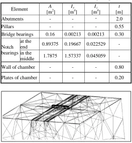
Tab. 3 Section characteristics of bridge elements
Element A
[m2]
Iy
[m4]
Iz
[m4]
t [m]
Abutments - - - 2.0
Pillars - - - 0.55
Bridge bearings 0.16 0.00213 0.00213 0.30
Notch bearings
at the
end 0.89375 0.19667 0.022529 -
in the
middle 1.7875 1.57337 0.045059 -
Wall of chamber - - - 0.80
[image:2.612.313.576.326.611.2]Plates of chamber - - - 0.20
Fig. 4 Detail of the bridge structure in 3D FEM model
B.2 Results from the calculation – The first custom shape and the first custom frequency
There are bending and torsional shapes of custom vibration and that because of entering the third dimension into the FEM model. But we can find here also the interactive shapes of vibration between the structure and the bedrock. The consequence is that the first custom frequency which belongs to the first custom shape of vibration in 2D FEM, is consistent with the fourteenth custom frequency of the custom vibration. This custom frequency belongs to the fourteenth custom shape of vibration in 3D FEM model.
The value of the fourteenth custom frequency f14 = 20.1Hz
belongs to the fourteenth custom shape of vibration, that is shown on the Fig. 5.
Fig. 5 – The 14th custom shape of vibration in 3D FEM model
IV. THEIMPULSELOADANDITSAPPLICATION
INTOTHEFEMMODELS
[image:3.612.37.300.58.186.2]In this case, technical seismicity is represented by the impulse load, which was concluded at the experimental investigation of the bridge. There was a need to put the time flow of the force impulse into both FEM models to analyze it. It was put onto a point, where it was generated “in situ”. The results of this calculation are these parameters: values of the velocity propagation and acceleration propagation of the force impulse response, value of the bridge structure displacement. All these parameters are values in the centre of the middle span.
[image:3.612.313.577.239.430.2]Fig. 6 – Time history of the force impulse intensity
Fig. 7 – The force impulse positioning into the point of turning lane facing in direction of travel Čadca – Žilina in 2D and 3D FEM model
A. 2D FEM model
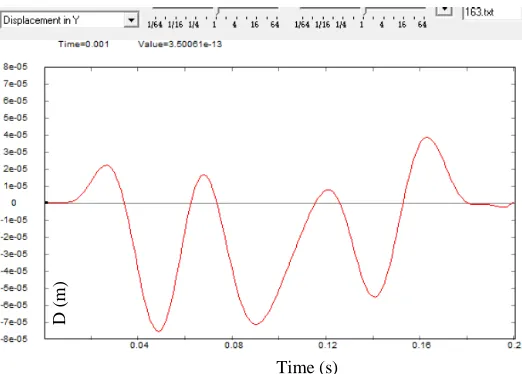
A.1 Results of the analysis
Fig. 8 – Time history of the displacement in the center of the middle span from the force impulse effect
Time (s)
F
or
ce
i
m
pu
ls
e (
kN
)
Time (s)
D
(m
[image:3.612.35.301.371.470.2] [image:3.612.314.575.502.689.2]Fig. 9 – Time history of the velocity propagation of the force impulse response in the center of the middle span
Fig. 10 – Time history of the acceleration propagation of the force impulse response in the center of the middle span
B. 3D FEM model
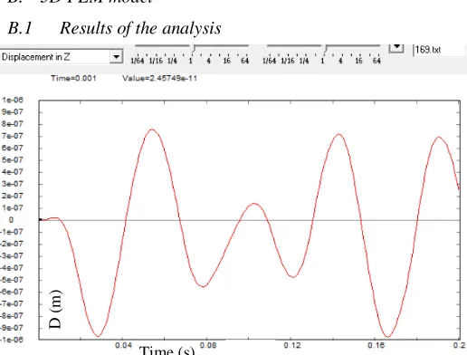
B.1 Results of the analysis
[image:4.612.40.297.268.460.2]Fig. 11 – Time history of the displacement in the center of the
[image:4.612.314.575.271.460.2]Fig. 12 – Time history of the velocity propagation of the force impulse response in the center of the middle span
Fig. 13 – Time history of the acceleration propagation of the force impulse response in the center of the middle span
V. CONCLUSION
There were created two FEM models of the real bridge M5973 Brodno for needs of investigation.
Both FEM models are usable for dynamic analysis. However, most exact one is 3D FEM model, because the results are absolutely identical to the results of our experimental investigation. By this theoretical way, we verified usability of the FEM model in a vibration propagation and usability of this model for another types of load (an impact load, natural seismicity, an explosion). [2], [3].
ACKNOWLEDGMENT
This contribution is the result of the project implementation: "Support of quality of education and research for area of transport as an engine of economics“, (ITMS: 26110230076) supported by the Operational Program Education funded by the European Social Fund.
Time (s)
V
(m
/s
)
Time (s)
A
(m
/s
2 )
D
(m
)
Time (s)
Time (s)
V
(m
/s
)
Time (s)
A
(m
/s
[image:4.612.39.297.513.709.2]REFERENCES
[1] Surface characteristics. Technical Report No. 1. XVIII. World Road Congress, Brussels: 1987
[2] J.P WOLF, Dynamic Soil Structure Interaction, Prentice Hall, Inc., Engelwood Cliffs, New Yersey, 1985
[3] J. Melcer, “Dynamické výpočty mostov na pozemných komunikáciách. Žilina” in EDIS, 1nd ed. Ed. Žilina: EDIS, 1997, pp. 287. [4] D. Kuchárová, J. Melcer, “Dynamika stavebných konštrukcií. Žilina” in
EDIS, 1nd ed. Ed. Žilina: EDIS, 2000, pp. 199.
AUTHORS
First Author – Katarína Demeterová, Ing., University of Žilina, Department of Structural Mechanics,
Second Author – Daniel Papán, Ing., PhD., University of Žilina, Department of Structural Mechanics,