A COMPARATIVE PERFORMANCE ANALYSIS OF O-OFDM-IDMA AND
O-OFDMA SCHEME FOR VISIBLE LIGHT COMMUNICATION
(LOS AND NLOS CHANNELS) IN OPTICAL DOMAIN
Abhishek Tripathi
1, R. K. Singh
2and S. K. Sriwas
3 1Abdul Kalam Technical University, Lucknow, India
2
Kamla Nehru Institute of Technology, Sultanpur, India
3
Bundelkhand Institute of Engineering and Technology, Jhansi, India E-Mail: [email protected]
ABSTRACT
In this paper we proposed the system model for o-ofdm-idma and o-ofdma in vlc channel (visible light communication as a media) and compared their performances in terms of receivers decoding complexities, BER (Bit Error Rate) and PAPR (Peak to average power ratio). For asymmetric clipping at zero both the multicarrier transmission schemes are tailored after OFDM modulation. The result of simulation shows that O-OFDM-IDMA is very power efficient in comparison to O-OFDMA for higher throughput values for the exceeding threshold value at a cost of higher decoding and computational complexity involved. The PAPR variation is not much significant for O-OFDM-IDMA and O-OFDMA. These results can be used as a basis for designing future Visible Light Communication based networks.
Keywords: O-OFDM-IDMA, O-OFDMA, VLC, OFDM, IDFT, MAI, PAPR, LOS and NLOS etc.
1. INTRODUCTION TO VLC TECHNOLOGY
It is a data communication alternative which uses visible light in the frequency range of 400-800THz (equivalent wavelength range of the order of 780-375nm) as a transmission medium. It can be termed as a fragment of Optical Wireless Communication technology. It is used for providing a data link through the illuminating devices like white Light-emitting diodes etc. Therefore it becomes economically important pervasive data transmission medium. Visible light is not harmful for human beings in contrast to radio waves and the regulation of spectrum is also absent in it [4]. These features make VLC to emerge as an attracting and efficient option for short range wireless communication technology [1]-[3]. It is evolving toward a new network called as Li-Fi (Light Fidelity) which can be termed as a complementary and enhancement of Wi-Fi network [5]. Various feasible standards which support the single carrier transmission based modulation schemes for Li-Fi is JEITA CP-1221, CP-1222 [6] and IEEE 802.15.7 [7]. By using multicarrier transmission technique OFDM (Orthogonal frequency division multiplexing) higher data rates can be achieved. OFDM allows parallel transmission on orthogonal subcarriers with low complexity transceiver system [8]. This paper compares the performance analysis of two potential candidates namely; optical orthogonal frequency division multiplexing interleave division multiple access (O-OFDM-IDMA) and as the second candidate; optical orthogonal frequency division multiple access (O-OFDMA) when the VLC is used as the medium of transmission for both the candidates. The paper involves the evaluation and the comparison of Bit Error Rate (BER), complexities involved in the designing of the receiver and the PAPR (Peak to average power) ratio for different cases. The paper is organized as: Section II gives the modelling of medium of transmission (VLC Channel) and the section III includes the model of O-OFDMA and
O-OFDM-IDMA. Section IV contains the related simulations and performance evaluation. At last the Section V provides the Conclusion of the paper and the discussions involved.
2. MODEL OF VLC (VISIBLE LIGHT COMMUNICATION) BASED CHANNEL
nature of the transmitted signal to be positive and real in nature. Also there should be no explicit carrier possessing single frequency but the light intensity needs to be modulated. The input-output relationship in time domain is given by the equation;
Y(t)=∑ 𝑥 𝑡 ∗ ℎ 𝑡 + z(t) (1)
[image:2.595.58.285.281.450.2]Where Y(t) is the received signal, 𝑥 𝑡 is the transmitted signal for user k, z(t) is the noise in the electrical domain, ℎ 𝑡 is the impulse response of the channel for user k and the symbol * is used for denoting the convolution operator. The impulse response of the channel includes the decay of the light propagation as well as the responsivities of both the LED and photodetector.
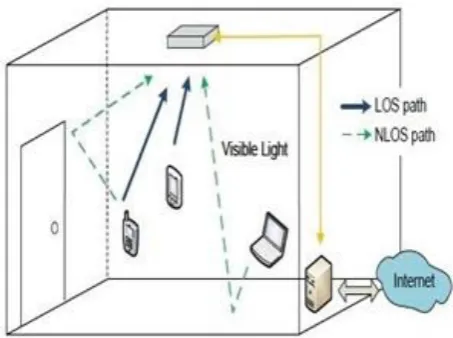
Figure-1. Showing an example of a VLC system for both the LOS and NLOS path.
2.1 Model of optical OFDM-IDMA system
It is originally proposed in radio frequency [9]. OFDM-IDMA is a multiple access power efficient scheme which is having lower extent of decoding complexity in contrast to others. The decoding complexity is independent of the number of multipath and varies linearly with the users in count.
Here the O-OFDM-IDMA based uplink transmission system with N subcarriers and K users are considered for the modelling, evaluation and comparison purpose. The figure 2 explains the Block diagram (discrete time) of the transmitter and receiver for K number of users. At the transmitter end the first element in the block diagram is the channel encoder which encodes the information bits for each user in to their corresponding coded bits. For kth user the information bit uk are first encoded to its corresponding coded bits bk. The second element in the transmitter block is spreader which in turn spread up the coded bits bk with a length-S spreading sequence denoted by si = − 𝑖 where i = 0,1,2,..., S-1. These spreaded bits are denoted by ck and are termed as chips. These chips are passed through user specific random interleaver’s ∏k for interleaving. This interleaving becomes the only basis for distinguishing the signals from different users; hence it is
termed as IDMA (Interleave Division Multiple Access). These interleaved chips are passed through Symbol mapper in order to carry out the process of modulation and get these interleaved chips modulated using QPSK modulation scheme, resulting in the modulated symbols Xk; which are further modulated to subcarriers via N-point IDFT (Inverse discrete time Fourier Transform) module. The signal after IDFT (in time domain) is xk.
For maintaining the compatibility with VLC channel; the resultant signal as the output of cyclic prefix adder (which modulates the light intensity) must be positive and real in nature. This is an additional condition for O-OFDM-IDMA in contrast to its counterpart in radio frequency based communication. For satisfying this requirement we have used the aspect as is explained in [10] which is the most effective and efficient solution than the other solutions. The Samples Xk (in frequency domain) is firstly expanded with Hermitian symmetry and after that loaded it into only the odd subcarriers of the IDFT module. Therefore the resultant signal is 𝑋̃ (in frequency domain) which is constructed from Xk. The time domain signal xk is clipped asymmetrically in order to set the negative samples to zero and keep all the positive samples as it is; yielding a signal (clipped)xc,k which is positive as well as real in nature both. After that cyclic prefix is added to the head of the clipped signal xc,k to generate the resultant signal; this generated signal is referred as an OFDM symbol. This OFDM symbol modulates the intensity of the Light Source (LED). On the receiver end, the first element used is the photo detector for transforming the optical power into the electric current. The cyclic prefix (CP) of the encoded OFDM symbol is discarded in time domain and then followed by an N-point DFT (Discrete Fourier Transform). And the resultant frequency domain sample Y(n) (on an odd subcarrier-n) is given by the below equation in accordance to (1) and [10]:-
Y(n)=∑𝐾= 𝐻 𝑛 𝑋̃ 𝑛 +Z(n)= (1/2) 𝐻 𝑛 𝑋̃ 𝑛 + 𝑉 𝑛 (2)
Where 𝐻 𝑛 is the kth user frequency response (on nth subcarrier), Z(n) is the AWGN (Additive White Gaussian Noise in frequency domain), 𝑉 𝑛 is termed as the complete interference term (it includes noise and MAI(multiple access interference) both for kth user on nth subcarrier).
𝑉 𝑛 can mathematically be expressed as:
𝑉 𝑛 =∑𝐾= , # 𝐻 𝑛 𝑋̃ 𝑛 +Z(n) (3)
ground of signs of Lp(uk)s. In Optical OFDM-IDMA, the samples (belonging to odd subcarriers) are sent to the elementary signal estimator (ESE) which de-multiplex the complete signal and generates the extrinsic log likelihood ratio Le(ck) (as per the input-output relationship in equation2). The elementary signal estimator treats the interference term as a complex Gaussian random variable Vk(n) and its mean value is estimated from the a priori log likelihood ratio La( 𝑐̃ )where l # k. The output of Elementary Signal estimator is applied as an input to user specific interleaver (in IDMA)in order to de-interleave the version of Le( 𝑐̃ ) and generate La(ck) from it. The generated La(ck) is passed through the de-spreader to yield La(bk) from it. At the reception end APP (A Posteriori Probability) based decoding technique is used [11],[12]. It involves the use of SISO (Soft input Soft output) decoder and evaluates the Lp(uk) and Le(bk) on the basis of La(bk) and the structure of the code. During the back iteration Le(bk) is spreaded and hence resulting in Lp(ck).The Lp(ck) and La(ck) is applied as a input to summer which computes the difference between them; generates the output Le(ck)= Lp(ck)- La(ck). The yielded Le(ck) is applied as an input to interleaver during the back iteration; and the resultant interleaved data (La( 𝑐̃ )) is fed as an input to Elementary Signal Estimator (ESE). The APP Decoder (A posterior Probability Decoder (Soft input- Soft output)) and ESE together perform the above procedure in an iterative fashion resulting in very refined result after each and every additional iteration resulting in the smooth functioning of the entire decoding process. After the last iteration Lp(uk) is used for estimating the information bits in accordance of their signs. The O-OFDM-IDMA possesses more than one layer, and these layers are referred as virtual users. By summing up the output of every layer together, the data rate can be varied as per the requirements of the different applications. At the reception end the numbers of virtual users are utilized rather than the original number of users (K).
Figure-2. Transceiver structure of O-OFDM-IDMA for kth user.
2.2. Model of optical OFDMA
The Figure-3 shows the transceiver structure of an optical OFDMA system. The channel encoder encodes the kth user information bits uk in order to get the coded bits bk. These encoded bits is interleaved and the resulting pattern (interleaved pattern)is then mapped to M-ary QAM constellation based symbol. The resultant mapped symbols Xk are then further processed to generate a new signal 𝑋̃ by passing through a Subcarrier assignment module. 𝑋̃ is then loaded to an IDFT module (N-point based). The final signal in time domain must be positive and real as same as that in O-OFDM-IDMA. And the methodology [10] is adopted for making the final signal real and positive. O-OFDM-IDMA and O-OFDMA possess few differences in their transmitter section these are as follows: I) In O-OFDMA Change in the data rate is possible by simply selecting the different size of modulation M; while the same can be achieved in O-OFDM-IDMA by adding the virtual user 2) User specific Interleavers are used in O-OFDM-IDMA; while in O-OFDMA generally the interleavers are same and 3) In O-OFDMA a sub carrier assignment module is used in order to exclusively devote each subcarrier to only one user. O-OFDMA involves the loading of non-zero data to only (1/K) fraction of the total odd subcarriers.
At the reception end the first element used is photodetector for transforming the received power of light in to the stream of current. After that the cyclic prefix is removed from the output of the photodetector. The next element in the receiver circuitry is DFT which in turn results in signal (on an odd subcarrier-n) is given as:
Y(n)= 𝐻 𝑛 𝑋̃ 𝑛 +Z(n) (4)
rule of the constellation (it represents a standard function [13]) and a priori LLRs.
Figure-3. Transceiver structure of O-OFDMA for kth user.
3. COMPARISON OF PERFORMANCE
3.1 Performance comparison on the basis of decoding complexities involved at the reception end
Complexities involved in the decoding of the above two systems (O-OFDM-IDMA & O-OFDMA) are about of the same order as indicated in [17], which is verified also during the simulations. As a result of simulation the performance of O-OFDMA does not varies by large extent with iterations as a varying parameter. For the convergence of BER curve only a single iteration is much sufficient and this result also maintains the consistency with the simulations in [18]. It may be because of the result of orthogonality involved in transmission hence it leads to absence of MAI that need not to be removed by opting the Iterative processing techniques. While in case of O-OFDM-IDMA, for convergence of BER curve sufficient numbers of iterations are required. Considering the above view; we can conclude that in O-OFDM-IDMA the complexity is Z (where Z is the number of iterations required in O-OFDM-IDMA) times greater than the decoding complexity involved in O-OFDMA.
3.2 Performance comparison on PAPR (Peak to average power ratio) basis.
PAPR is simply the square of the crest factor and it defines the ratio of peak power (peak amplitude squared) to the average power (RMS value squared). It is one of the major parameter used for defining the performance of various transmission schemes. Higher PAPR demonstrate the higher potential non linear distortions while in digital communication system higher PAPR signify the requirement of larger number of bits in order to approximate the continuous signal and thus leading to higher complexity [19]. In O-OFDMA the lower value of PAPR is the requirement because the associated asymmetric clipping with it; the peak current (instantaneous) may drop down in the non linear range of transfer function of LED. The mathematical expression for calculation of PAPR of a signal (discrete time) x(n) where n= 0,1,2,...N-1 is as below:
PAPR = ((max⃓𝑥 𝑛 ⃓ ) for ≤ 𝑛 ≤ 𝑁 − / ((1/N)
∑𝑁− ⃓𝑥 𝑛 ⃓
𝑛= ) (5)
In case of random waveforms; for characterization of PAPR the complementary cumulative distribution function (CCDF) is generally used. It simply defines the probability of Peak to average Power ration exceeding than the already predetermined certain threshold. Mathematically; CCDF (z) = Pr (PAPR > z). Lower CCDF is always preferred over the larger ones for a fixed-threshold.
Figure-4. Comparison of complementary cumulative distribution.
3.3 Function curves for optical OFDM-IDMA and optical OFDMA
The Figure-4, shows the CCDFs of O-OFDMA with M=4, 16, 256 and O-OFDM-IDMA with L= 1, 2 and 4 (M=256 corresponds to L=4), for generalization Gray mapping is assumed.
For O-OFDM-IDMA with increase in the number of layers (L) the CCDF increases which states that the probability of PAPR exceeding than the pre determined threshold increases. While; in O-OFDMA with increase in the modulation size (M) CCDF decreases. The variation in CCDF for O-OFDM-IDMA is more in comparison with O-OFDMA. The performance of O-OFDMA is consistent with radio frequency counterpart also and it can be approximated as expression mentioned in [19]. In O-OFDM-IDMA the entire signals transmitted are positive and real in nature and it is equals to the sum of all the L (layers) components used in it. The numerator term (Peak Power) in PAPR grows faster than the denominator term (Aggregate average power) with increase in the number of layers (L) resulting in higher PAPR values. From the above figure the lower CCDF can be expected in O-OFDM-IDMA for only lower throughput of system.
3.4 Performance comparison on BER (bit error rate) basis
also need to be satisfied during making the fair BER comparison between the two potential candidates (O-OFDMA & O-OFDM-IDMA). For unbiased comparison the system transmission is carried out at the same data rate over the same bandwidth for both the schemes. Convolution coding scheme with coding rate ½ and generator (23, 35)8 is used for both the schemes for providing the common and similar platform for comparison. Using these constraints we can easily able to establish a relation between numbers of layers L, spreading length S for every user in O-OFDM-IDMA and the size of modulation in O-OFDMA.
L=(Slog2M)/(2K) (6)
In the simulations performed the number of users K=8, spreading length=8, number of subcarriers= 512, and number of layers (O-OFDM-IDMA) =1, 2 and 4. The corresponding modulation size (O-OFDMA) 4 QAM equivalent to L=1, 16 QAM equivalent to L=2 and 256 QAM equivalent to L=4.
For checking the variation of impulse response of the LOS and NLOS channels with respect to variation in time; the simulation system as discussed in [14] is used. For modelling of channel and creating the ambience for transmission in the following way the assumptions are made:
Figure-5. LOS and NLOS channels (an illustrative view).
A vacant room with the dimension Length of 8m, width of 6m and height of 4m is used. The reflection coefficient for the floor is 0.3 and for walls and ceiling it is 0.8. The transmitter is placed at a height 1m above the surface of the floor directing in the strict upward direction. For line of sight (LOS) channels the receiver is fixed and is directed downward toward the surface of the floor & for non line of sight (NLOS) channels the receiver is placed at the centre of the surface of the floor directing upwards.
Sampling rate is 100 MHz. For realization of every channel transmitter locations are distributed in random fashion. In order to carry out the realizations of the channels 50 realizations randomly generated have been performed for both the LOS and NLOS channel. After that these are normalized to unity and hence used for simulating the average BER performance. The figure 5 shows a view of LOS and NLOS channels before the process of normalization. From this figure we can easily observe that the LOS channel is having much more power than the NLOS channel. Some reflected component of the NLOS path is also the part of LOS channel hence resulting in the dominancy of the LOS path over the channel.
Figure-6. Bit error rate performance in line of sight (LOS) channels.
Figure-7. Bit error rate performance in non line of sight channels.
In the entire two cases the BER performance of O-OFDM-IDMA is dominating over the performance of O-OFDMA for larger values of Eb/No (exceeding the threshold limit set). With increase in the number of virtual users (increase in throughput) and for NLOS channel the O-OFDM-IDMA is dominating in terms of power efficiency in contrast to O-OFDMA. Spreading involved in O-OFDM-IDMA for NLOS channel results in combining the frequency diversity hence better performance can be expected from it. As O-OFDM-IDMA is a multiple access scheme (non-orthogonality based), the signal from the various users are non orthogonal and can be separated by opting the Iterative Soft Interference Cancellation while the O-OFDMA is an orthogonal scheme. Hence we can expect the higher power efficiency in non orthogonal system in comparison to the orthogonal ones by utilizing the multi user gain (MUG) [15], [16]. It is the theoretical ly supporting our simulation results.
4. CONCLUSIONS
This paper involves the comparison of multiple access schemes (multicarrier based) in visible light communication channel as a transmission media. The result of simulation shows that O-OFDM-IDMA is more power efficient in comparison to O-OFDMA while in terms of decoding complexity O-OFDMA outperforms over the O-OFDM-IDMA. Hence it results in lower decoding complexity in OFDMA in comparison to O-OFDM-IDMA. The peak to average power ratio performance of O-OFDM-IDMA is some less significant than O-OFDMA for higher values of throughput; with a critical exception for the lower throughput where L=1 and M=4 values. These critical observations can be used as a basis for designing future VLC (visible light communication) system and networks.
REFERENCES
[1] D.O’ Brien, L. Zeng, H. Le-Minh, G Faulkner, J. Walewski and S. Randel. 2008. Visible Light Communications: challenges and possibilities. in
proc. IEEE Int. Symposium on Personal, Indoor and Mobile Radio Communications, Cannes, France. pp. 1-5.
[2] Y. Zheng and M. Zhang. 2011. Visible Light Communications-recent progresses and future outlooks. in Proc. 2010 Symp. On Photonics and Optoelectronic, Chengdu, China. pp. 1-6.
[3] D. O’Brien. 2011. Visible Light communications: challenges and potential. in proc. 2011 IEEE Photonics Conference, Arlington, Virginia, USA. pp. 365-366.
[4] C. Pohlmann. 2010. Visible Light communication. tech. Rep., 2010. Also available as http://www.-old.itm.uni-luebeck.de/teaching/ss10/
sem_kim/ausarbeitungen/2010-06-29%20Pohlmann.%20Visible%20Light%20Communi cation.pdf?lang=de.
[5] (Li-Fi)-Consortium.
http://lificonsortium.com/index.html.
[6] Japan Electronics and information technology Industries Association. http://www.jeita.or.jp.
[7] IEEE 802.15.7 WPAN Task Group 7 (TG7) Visible Light-Communications.
http://www.ieee802.org/15/pub/TG7.html.
[8] Y. Cho, J. Kim, W. Yang and C. Kang. 2010. MIMO-OFDM Wireless Communications with MATLAB, Wiley-IEEE Press. pp. 111-151.
[9] I.M. Mahafeno, C. Langlais, and C. Jego. 2006. Reduced Complexity iterative multi-user detector for IDMA (Interleave-division multiple access) system. in Proc. of Global Telecommunications Conf., San Francisco, CA, USA. pp. 1-5.
[10]J. Armstrong and A. Lowery. 2006. Power Efficient Optical OFDM. Electronics Letters. 42: 370-372.
[11]C. Berrou and A. Glavieux. 1996. Near optimum error correcting coding and decoding: Turbo-codes. IEEE Trans. on Communications. 44: 1261-1271.
[13]J. Tan and G. Stuber. 2005. Analysis and design of symbol mappers for iteratively decoded BICM. IEEE Trans. on Wireless Communications. 4: 662-672.
[14]J. Carruthers and P Kannan. 2002. Iterative site-based modelling for wireless infrared channels. IEEE Trans. on Antennas and Propagation. 50: 759-765.
[15]P. Wang, J. Xiao and L. Ping. 2006. Comparison of orthogonal and non orthogonal approaches to future wireless cellular systems. IEEE Vehicular Technology Magazine. 1: 4-11.
[16]L. Ping. Wireless communication systems: orthogonal or non-orthogonal? tech. Rep. Also available at: http://www.cm.nctu.edu.tw/~ IEEE /ITComSoc/slides/4.pdf.
[17]L. Ping, Q. Guo and J. Tong. 2007. The OFDM-IDMA approach to wireless communications. IEEE Wireless communication systems 14: 19-24.
[18]Bit Interleaved Coded Modulation. Available at http://code.google.com/p/turbosiso/wiki/bicm.