http://dx.doi.org/10.4236/cn.2014.61004
A Novel Decoding Method for Non-Binary TCM Codes
Riyadh A. Al-Hilali1, Abdulkareem S. Abdallah2, Raad H. Thaher3 1
College of Engineering Al-Mustansiriyah University, Baghdad, Iraq
2
College of Engineering, Basrah University,Basrah, Iraq
3
College of Engineering, Al-Mustansiriyah University, Baghdad, Iraq Email:[email protected], [email protected], [email protected]
Received July 1, 2013; revised August 1, 2013; accepted August 8, 2013
Copyright © 2014 Riyadh A. Al-Hilali etal. This is an open access article distributed under the Creative Commons Attribution Li-cense, which permits unrestricted use, distribution, and reproduction in any medium, provided the original work is properly cited. In accordance of the Creative Commons Attribution License all Copyrights © 2014 are reserved for SCIRP and the owner of the intel-lectual property Riyadh A. Al-Hilali etal. All Copyright © 2014 are guarded by law and by SCIRP as a guardian.
ABSTRACT
A new non-binary decoding method, which is called Yaletharatalhussein decoding algorithm, is designed and implemented for decoding non-binary convolutional codes which is based on the trellis diagram representing the convolutional encoder. Yaletharatalhussein decoding algorithm outperforms the Viterbi algorithm and other algorithms in its simplicity, very small computational complexity, decoding reliability for high states TCM codes that suitable for Fourth-Generation (4G), decreasing errors with increasing word length, and easy to implement with real-time applications. The proposed Yaletharatalhussein decoding algorithm deals with non-binary error control coding of the convolutional and TCM codes. Convolutional codes differ from block codes in that a block code takes a fixed message length and encodes it, whereas a convolutional code can encode a continuous stream of data, and a hard-decision decoding can easily be realized using the Yaletharatalhussein algorithm. The idea of non-binary codes has been extended for symbols defined over rings of integers, which outperform binary codes with only a small increase in decoding complexity. The simulation results show that the performance of the non- binary TCM-based Yaletharatalhussein algorithm outperforms the binary and non-binary decoding methods.
KEYWORDS
Convolutional Codes; Coded Modulation (CM); Trellis Code Modulation (TCM); Non-Binary Error Correcting Codes; Groups; Rings of Integers
1. Introduction
When conventional coding techniques are introduced in a transmission system, the bandwidth of the coded signal after modulation is wider than that of the uncoded signal for the same information rate and the same modulation scheme. In fact, the encoding process requires a band-width expansion that is inversely proportional to the code rate, being traded for a coding gain. On the other hand, the available radio spectrum is limited and the commu-nication capacity needs cannot be met without a signifi-cant increase in spectral efficiency [1]. Digital signals are more reliable in a noisy communications environment. They can usually be detected perfectly, as long as the noise levels are below a certain threshold. Digital data can easily be encoded in such a way as to introduce de-pendency among a large number of symbols, thus enabl- ing a receiver to make a more accurate detection of the
symbols. This is called error control coding. The design of signal processing algorithms for digital data seems much easier than designing analog signal processing al-gorithms. The abundance of such digital algorithms, in-cluding error control and correction techniques, combined with their ease of implementation in very large-scale integrated (VLSI) circuits, has led to many successful applications of error control coding in practice.
Advances in coding, such as turbo [2] and low density parity check codes [3], made it feasible to approach the Shannon capacity limit [4] in systems with a single an-tenna link. Significant further advances in spectral effi-ciency are available through increasing the number of antennas at both the transmitter and the receiver [5-7].
binary codes are the most commonly used error-correct- ing codes and can be found in optical and magnetic sto-rage, high-speed modems and wireless communications.
Among the various Coded Modulation (CM) schemes, TCM [9] was originally designed for transmission over Additive White Gaussian Noise (AWGN) channels. TTCM [10] is a more recent joint coding and modulation scheme which has a structure similar to that of the family of bi-nary turbo codes, but employs TCM schemes as compo-nent codes. Both TCM and TTCM employ set-partition- ing-based constellation mapping [11], while using sym-bol-based turbo interleavers and channel interleavers. Another CM scheme, referred to as BICM [12], invokes bit-based channel interleavers in conjunction with grey constellation mapping. Furthermore, iteratively decoded BICM [13] using set partitioning was also proposed.
2. Rings of Integers
If the two binary operations “+” and “·” are allowed then a ring can be defined. A ring must have the following conditions; associativity, distributivity, and commutativ-ity under addition. The ring is called a commutative ring if it also has commutativity under multiplication. If the ring has a multiplicative identity 1 then it is called a ring with identity. An example of a ring is the ring of integers
q
under modulo-q addition and multiplication, where
q is the cardinality of the ring. For example, 4 is defined
as {0, 1, 2, 3}.
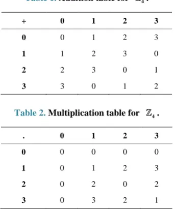
It is easy to see that the elements obey the three defini-tions of a ring. Also, all the elements commute under multiplication and the multiplicative identity element 1 is present, meaning that 4 is a commutative ring with
identity. Tables 1 and 2 show the addition and multipli-cation tables respectively of the ring of integers
{
}
4= 0, 1, 2, 3
[14].
Table 1. Addition table for 4.
+ 0 1 2 3
0 0 1 2 3
1 1 2 3 0
2 2 3 0 1
[image:2.595.87.260.531.737.2]3 3 0 1 2
Table 2. Multiplication table for 4.
. 0 1 2 3
0 0 0 0 0
1 0 1 2 3
2 0 2 0 2
3 0 3 2 1
The set of all polynomials with coefficients defined in
q
forms a ring under the addition and multiplication operations.
3. Non-Binary TCM
Convolutional codes and TCM codes are based on rings of integers modulo-M. Due to the similarities between M-PSK signal sets and the algebraic structure of rings of integers modulo-M, modulo-M ring-TCM codes are the natural linear codes for M-PSK modulation.
TCM Based on Rings of Integers
The general structure of a ring-TCM encoder suitable for M-PSK modulation, assuming that m information bits are transmitted per baud, with M=2m+1, is shown in Figure 1. This ring-TCM encoder works as follows [15]:
1) First, m + 1 information bits, bi, are mapped into a
modulo-M symbol, aj, according to a mapping function
f (for instance, f can be a Gray mapping function). 2) Next, m modulo-M aj symbols are introduced into a linear multi-level convolutional encoder (MCE), which generates m + 1 modulo-M coded symbols, xk.
3) Finally, each one of these coded symbols xk is
associated with a signal of the M-PSK signal set and is sent to the channel.
As a total of m + 1 modulo-M coded symbols xk are
transmitted per single trellis branch, ring-TCM codes can be considered as 2
(
m+1)
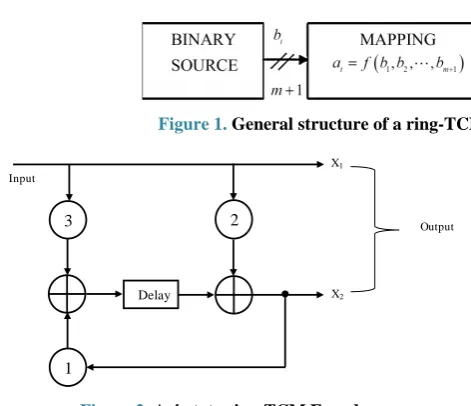
-dimensional TCM codes.4. A 4-State Ring-TCM Code Defined over 4
A good 4-state ring-TCM code over 4 is shown in
Figure 2 and this would be used in this research work [16].
Where each of the input and output of Figure 2 represent the elements of the ring of integers modulo-4,
{
}
4= 0,1, 2, 3
, and all addition arithmetic operations satisfy the properties of the ring of integers modulo-4 addition. The delay block represents the constraint length (number of memory elements, i.e., in this case there is only one memory element).
5. Yaletharatalhussein Decoding Algorithm
The Yaletharatalhussein non-binary decoding algorithm is proposed in this paper for decoding non-binary convo-lutional codes. The decoder for the non-binary convolu-tional code finds the most probable sequence of data bits
ˆ
u given the received sequence y:
( )
ˆ arg max
u
u= p u y
(1)
Figure 1. General structure of a ring-TCM encoder suitable for M-PSK modulation.
Figure 2. A 4-state ring-TCM Encoder.
tharatalhussein algorithm, explained later.
The application of the Yaletharatalhussein algorithm to decoding non-binary convolutional codes is based on the logic similarities and differences, at each time instant, between the noisy received bits, i.e., y, and the sequence of output data bits, i.e., u, of the non-binary state table that represents the non-binary convolutional encoder se- quential logic states.
This principle states that creating a state vector con-taining binary logic states, which represents the similari-ties and differences between y symbols associated with each u bits at the current time instant, and then searching for a minimum logic state in this vector to determine the state node number with its order bit for using in the next time instant of searching strategy method, in one hand, and for recovering the transmitted code word in the other hand. In this case, the decoding method is independent on the trellis diagram representing the non-binary con-volutional encoder.
The basic steps in the Yaletharatalhussein non-binary decoding algorithm can be described as follows:
1) Determine the logic state vectors that represent the logic similarities and differences between the first block noisy received symbols, y, associated with each output data bits vector of all states, u, at each time instant (i.e., t
= 0 to t = K), according to the following condition:
(
)
(
)
0, iff bits are similar
( )
1, iff bits are disimilar
y u
h u y
y u = = & ⊙
& (2)
where:
⊙: represents a non-binary operation defined above;
y: represents noisy received symbols with K, word length and;
u: represents a vector of non-binary output data bits for all states at the current time instant associated with y
symbol, and the length of this vector is
( )
nst 2, where stn , is the number of non-binary states of the convolu-tional encoder. Thus the vector h would contain a set of ones and zeros (i.e., binary vector).
2) Begin at time t = K, at state 0.
[image:3.595.122.471.85.128.2]3) Search about the zero logic state in h vector at this current time instant (i.e., t = K), and then store both number of state node and the order of the determined zero logic state to detect the transmitted bit at this time instant (i.e., x at t = K) from the input vector in the state table.
4) Decrement time t (i.e., t = K − 1) and return to Step
3, but search about the zero logic state in the h vector locations only, that have order the same as the state node number that stored in Step 3. Then the transmitted bit at this time instant (i.e., x at t = K − 1) can be detected from
the input vector in the state table. In this case the search-ing about zero locations would be decreased.
5) Continue this process until all the symbols in the code word have been detected at the final time instant (t
= 0).
An example of applying the Yaletharatalhussein de-coding algorithm for the non-binary 4-ring-TCM
en-coder shown in Figure 2, the encoder takes an input se-quence bits x of length K bits and for each bit produces two coded bits denoted as y1 and y2.
For simplicity, assuming K = 5 bits, and noiseless data vector y2 is received at the non-binary decoder input. If
the input message to the non-binary 4-ring-TCM
en-coder is:
x = [1 2 3 3 3], then the coded bits y1 and y2 are
described below:
1
y = [1 2 3 3 3], and y2 = [2 1 1 0 3].
Now, from the state table [16], the initial input vectors
w’s and output data vectors u’s are shown below, where each script number indicates time instant k:
1
1 2 3 4 5
[0 1 2 3 3 0 1 2 2 3 0 1 1 2 3 0], ,
w
w w w w w
=
= = = =
and
1
1 2 3 4 5
[0 2 0 2 3 1 3 1 2 0 2 0 1 3 1 3], , [0 3 2 1].
u
u u u u u
=
= = = =
The steps of applying the Yaletharatalhussein decod-ing algorithm are described below:
1) To find h vectors, using the relation (4.15) then:
h1 = [1 0 1 0 1 1 1 1 0 1 0 1 1 1 1 1],
h2 = [1 1 1 1 1 0 1 0 1 1 1 1 0 1 0 1],
h3 = [1 1 1 1 1 0 1 0 1 1 1 1 0 1 0 1],
h4 = [0 1 0 1 1 1 1 1 1 0 1 0 1 1 1 1],
h5 = [1 0 1 1],
2) Search in h5 = [1 0 1 1], about zero element, this leads to [1; 0; 1; 1], this assigned in state node number = 2, and bit order = 1. Thus the transmitted bit in w5 = [0 1 2 3; 3 0 1 2; 2 3 0 1; 1 2 3 0], is x5 = 3.
3) Search in h4 = [0 1 0 1 1 1 1 1 1 0 1 0 1 1 1 1], about zero element in the 2nd location of each state of h4, this leads to [0 1 0 1; 1 1 1 1; 1 0 1 0; 1 1 1 1], and as-signed in state node number = 3, and bit order = 10. Thus the transmitted bit in w4 = [0 1 2 3 3 0 1 2 2 3 0 1 1 2 3 0], is x4 = 3.
4) Search in h3 = [1 1 1 1 1 0 1 0 1 1 1 1 0 1 0 1], about zero element in the 3rd location of each state of h3, this leads to [1 1 1 1; 1 0 1 0; 1 1 1 1; 0 1 0 1], and as-signed in state node number = 4, and bit order = 15. Thus the transmitted bit in w3 = [0 1 2 3 3 0 1 2 2 3 0 1 1 2 3 0], is x3 = 3.
5) Search in h2 = [1 1 1 1 1 0 1 0 1 1 1 1 0 1 0 1], about zero element in the 4th location of each state of h2, this leads to [1 1 1 1; 1 0 1 0; 1 1 1 1; 0 1 0 1], and as-signed in state node number = 2, and bit order = 8. Thus the transmitted bit in w2 = [0 1 2 3 3 0 1 2 2 3 0 1 1 2 3 0], is x2 = 2.
6) Search in h1 = [1 0 1 0 1 1 1 1 0 1 0 1 1 1 1 1], about zero element in the 2nd location of each state of h1, this leads to [1 0 1 0; 1 1 1 1; 0 1 0 1; 1 1 1 1], and as-signed in state node number = 2, and bit order = 2. Thus the transmitted bit in w1 = [0 1 2 3 3 0 1 2 2 3 0 1 1 2 3 0], is x1 = 1.
7) The transmitted bits sequence form the non-binary
4
-ring-TCM encoder is, x = [1 2 3 3 3], which is simi-lar to the given input message.
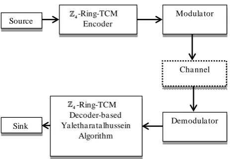
To enhance the Yaletharatalhussein decoding method, a schematic design of the 4-ring-TCM-based
Yaletha-ratalhussein algorithm is shown in Figure 3. The source information bits are first encoded and modulated by the
4
-ring-TCM encoder and modulater.
The symbols are then transmitted via the channel, and the received noise-contaminated symbols are forwarded to the demodulator.
The recovered signal is then demodulated and the outputs are fed to the 4-ring-TCM-decoder which used
the Yaletharatalhussein algorithm for recovering the most likely transmitted information bits.
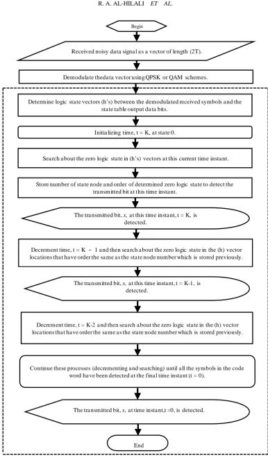
The 4-ring-TCM demodulator and decoder-based
Yaletharatalhussein decoding algorithm can be represented by a flowchart as shown in Figure 4. The flow chart in-side the dashed lines represents the Yaletharatalhussein decoding algorithm.
6. Simulation Results
The performances of the 4-Ring-TCM-PAM scheme-
based Yaletharatalhussein algorithm communicating over
Figure 3. Schematic diagram of the proposed 4-ring- TCM-based Yaletharatalhussein algorithm.
the AWGN channel are shown in Figure 5.
The performances of the 4-Ring-TCM-PAM scheme-
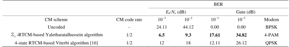
based Yaletharatalhussein decoding algorithm and the schemes of work [16] can be summarized in Table 3, where the coding gains are defined as the
(
Eb N0)
difference, expressed in decibels, at BERs of 10−5 and 10−3. The performance of the best scheme in Table 3 is (printed in bold), since the performance comparison shows that the 4-ring-TCM-PAM scheme-based
Yalethara-talhussein algorithm outperforms the 4-state ring-TCM- based Viterbi algorithm by the gains (5.5 dB and 8.7 dB) at the BERs (10−3 and 10−5) respectively.
7. Conclusions and Future Works
A novel non-binary decoding method, which is called Yaletharatalhussein decoding algorithm, is proposed for decoding non-binary convolutional and TCM codes, which independent on the trellis diagram representing the non- binary convolutional encoder, as in Viterbi algorithm.
The Yaletharatalhussein algorithm employed a hard- decision decoding, which needed less computational com-plexity over the soft-decision MLD of Viterbi algorithm. In Yaletharatalhussein algorithm, the code words are detected instantaneously through searching in the devel-oped state vectors, while in Viterbi algorithm, the ham-ming distances between numbers and transition metrics are calculated and a comparison between competitive accumulated metrics is done for every state of the trellis diagram.
Computational complexity of the Yaletharatalhussein algorithm is much smaller than complexity of the Viterbi algorithm, since in Viterbi algorithm, a survivor path of the lowest accumulated metrics is calculated and re-peated for every state of the trellis diagram.
In Yaletharatalhussein algorithm, the massages are decoded in blocks reached to 1,000,000 symbols as seen in simulation results, while in a typical Viterbi code,
Source
-Ring-TCM Encoder
Sink
Modula tor
Demodula tor -Ring-TCM
Decoder-ba sed Ya letha ra ta lhussein
Algorithm
Cha nnel
4
4
[image:4.595.309.541.81.241.2]Figure 4. Flow chart of the 4-ring-TCM demodulator-decoder-based Yaletharatalhussein decoding algorithm.
Received noisy da ta signa l a s a vector of length (2T).
Demodula te theda ta vector using QPSK or QAM schemes.
Determine logic sta te vectors (h’s) between the demodula ted received symbols a nd the sta te ta ble output da ta bits.
Initia lizing time, t = K, a t sta te 0.
Sea rch a bout the zero logic sta te in (h’s) vectors a t this current time insta nt.
Store number of sta te node a nd order of determined zero logic sta te to detect the tra nsmitted bit a t this time insta nt.
Begin
Decrement time, t = K − 1 a nd then sea rch a bout the zero logic sta te in the (h) vector loca tions tha t ha ve order the sa me a s the sta te node number which is stored previously.
The tra nsmitted bit, x,a t this time insta nt, t = K, is detected.
Decrement time, t = K-2 a nd then sea rch a bout the zero logic sta te in the (h) vector loca tions tha t ha ve order the sa me a s the sta te node number which is stored previously.
Continue these processes (decrementing a nd sea rching) until a ll the symbols in the code word ha ve been detected a t the fina l time insta nt (t = 0).
End
The tra nsmitted bit, x,a t time insta nt,t =0, is detected. The tra nsmitted bit, x,a t this time insta nt, t = K-1, is
[image:6.595.68.537.86.266.2]
Figure 5. The (BER) versus
(
Eb N0)
performance of the 4-Ring-TCM-PAM scheme-based Yaletharatalhussein algo-rithm.Table 3. Performance of the ring-TCM schemes.
BER
Eb/No (dB) Gain (dB)
CM scheme CM code rate 10−3 10−5 10−3 10−5 Modem
Uncoded - 24.11 44.12 0.00 0.00 BPSK
4
-RTCM-based Yaletharatalhussein algorithm 1/2 6.5 9.3 17.61 34.82 4-PAM
4-state RTCM-based Viterbi algorithm [16] 1/2 12 18 12.11 26.12 QPSK
messages are decoded in blocks of only about 200 bits or so, whereas in turbo coding the blocks are on the order of 16K bits long. Non-binary TCM codes outperform binary TCM codes with a small increase in decoding complexity. The use of non-binary TCM codes led to reduction in the effective input block length, since each m bits of binary information correspond to one non-binary symbol for q = 2m, and thus non-binary system can be used with high number of symbols.
A future work can be done by applying the Yalethara-talhussein decoding algorithm to higher order rings of integers such as, 8, 16, 32, and 64, and then
study the error performance and bandwidth efficiency of the system for different types of modulation schemes and orders: 8, 16, 32, and 64.
REFERENCES
[1] S. Ortiz, “4G Wireless Begins to Take Shape,” Computer, Vol. 40, No. 11, 2007, pp. 18-21.
http://dx.doi.org/10.1109/MC.2007.369
[2] C. Berrou and A. Glavieux, “Near Optimum Error Cor- recting Coding and Decoding: Turbo Codes,” IEEE Trans- actions on Communications, Vol. 44, No. 10, 1996, pp. 1261-1271. http://dx.doi.org/10.1109/26.539767
[3] R. Gallager, “Low Density Parity Check Codes,” IEEE Transactions on Information Theory, Vol. 8, No. 1, 1962,
pp. 21-28. http://dx.doi.org/10.1109/TIT.1962.1057683
[4] D. J. C. Mackay and R. M. Neal, “Near Shannon Limit Performance of Low Density Parity Check Codes,” Elec- tronics Letters, Vol. 33, No. 6, 1997, pp. 457-458.
http://dx.doi.org/10.1049/el:19970362
[5] B. Lu, X. Wang and K. R. Narayanan, “LDPC-Based Space-Time Coded OFDM Systems over Correlated Fad-ing Channels: Performance Analysis and Receiver De-sign,” Proceedings of the 2001 IEEE International Sym-posium on Information Theory, Washington DC, Vol. 1, 24-29 June 2001, p. 313.
[6] “Using MIMO-OFDM Technology to Boost Wireless LAN Performance Today,” White Paper, Datacomm Re-search Company, St Louis, 2005.
[7] H. Sampath, S. Talwar, J. Tellado, V. Erceg and A. J. Paulraj, “A Fourth-Generation MIMO-OFDM Broadband Wireless System: Design, Performance, and Field Trial Results,” IEEE Communications Magazine, Vol. 40, No. 9, 2002, pp. 143-149.
http://dx.doi.org/10.1109/MCOM.2002.1031841
[8] L. R. Bahl, J. Cocke, F. Jelinek and J. Raviv, “Optimal Decoding of Linear Codes for Minimizing Symbol Error Rate,” IEEE Transactions on Information Theory, Vol. 20, No. 2, 1974, pp. 284-287.
http://dx.doi.org/10.1109/TIT.1974.1055186
[9] L. Hanzo, T. H. Liew and B. L. Yeap, “Turbo Coding, Turbo Equalisation and Space-Time Coding,” IEEE Press and John Wiley & Sons, Ltd, Chichester, 2002.
[image:6.595.53.539.327.407.2][10] M. O. Damen, A. Chkeif and J.-C. Belfiore, “Lattice Code Decoder for Space-Time Codes,” IEEE Communications Letters, Vol. 4, No. 5, 2000, pp. 161-163.
http://dx.doi.org/10.1109/4234.846498
[11] M. O. Damen, H. E. Gamal and G. Caier, “On Maximum- Likelihood Detection and the Search for Closest Lattice Point,” IEEE Transactions on Information Theory, Vol. 49, No. 10, 2003, pp. 2389-2402.
http://dx.doi.org/10.1109/TIT.2003.817444
[12] B. Hochwald and S. ten Brink, “Achieving Near-Capacity on a Multiple-Antenna Channel,” IEEE Transactions on Communications, Vol. 51, No. 3, 2003, pp. 389-399.
http://dx.doi.org/10.1109/TCOMM.2003.809789
[13] D. Pham, K. R. Pattipati, P. K. Willett and J. Luo, “An
Improved Complex Sphere Decoder for V-BLAST Sys- tems,” IEEE Signal Processing Letters, Vol. 11, No. 9, 2004, pp. 748-751.
http://dx.doi.org/10.1109/LSP.2004.833522
[14] R. Carrasco, F. Lopez and P. Farrell, “Ring-TCM for M-PSK Modulation: AWGN Channels and DSP Imple-mentation,” IEE Proceedings of Communications, Vol. 143, No. 5, 1996, pp. 273-280.
http://dx.doi.org/10.1049/ip-com:19960738
[15] E. H. Connel, “Elements of Abstract and Linear Algebra,” Coral Gables, Florida, 2004.