- - - -
-- --
--- ---
-
- - . ~-
-- --
-- ====----
_.
----~--
-
--
-
---~- ===:" __
~1-- 1--
___
__ .. 1-
--
~. Application Program
1440/1460 Administrative Terminal System
(1440-CX-07X and 1460-CX-OBX)
Console Operator's Manual
This system consists of control and functional programs that permit many different
text-processing activities to be carried on simultaneously through different terminals.
H20-0227-0
PREFACE
The material in this manual relates to Version 2 of the IBM 1440/1460
Administrative Terminal System program. It obsoletes and replaces
the Preliminary Edition issued with Version 1 of the program.
This publication was prepared for production using the IBM 1440/1460
Administrative Terminal System. Page impressions for photo-offset
printing were obtained from a typewriter terminal and then reduced 15 percent.
Copies of this and other IBM publications can be obtained through IBM
Branch Offices. Address comments concerning the contents of this
CONTENTS
INTRODUCTION •••••••••• 0 • • • • • • • • • • • • • • • • • • • • • • • • • • • • • • • • 1
REAL-TIME OPERATIONS... 2
SYSTEM DESCRIPTION ••••
o...
3Basic Machine units of ATS... 3
IBM 1447 Console •••
e...
3Altering and Displaying Core... 6
Branching to an Address... 7
IBM 1448 Transmission Control u n i t . . . 7
IBM 1311 Disk Drives... 9
ATS Program ••••••••••• 0 • • • • • • • • • • • • • • • • • • • • • • • • • • • • • • • • 9 Program Overlays •••
e...
9Program Modifications... 10
Calling Programs from Disk Storage... 10
Program Layout and Operation... 10
Core Storage •••••••
e...
10Disk S t o r a g e . . . 12
BASIC ATS OPERATIONS ••
e...
19The First Day--Preparing to Run ATS... 19
Preparing the Disk Packs... 19
Patching System Parameters... 21
Loading the System... 25
Normal Operations... 26
Cycling the System Using the Card Reader... 26
Cycling the System Using the Console... 27
Shutting Down the System... 27
ATS utility Programs ••
II...
28Permanent Storage Maintenance--ATSDD... 28
Permanent Storage Backup... 29
Retrieval from Backup Tapes--ATSTR... 30
Single Sector Disk Dump--SSDD... 31
ATS Core Dump--CORED... 34
OPERATION OF ADDITIONAL ATS FEATURES... 36
Permanent Storage T a p e . . . 36
Storage Report on Printer or Tape... 37
System O u t p u t . . . 37
Terminal 99--Card Punch... 38
~I'erminal 98--Printout with Line Numbers... 38
~['erminal 97--Card Image Magnetic Tape... 39
~rerminal 96--Upper- and Lowercase Chain Printer •••• 39 System Output--Alternate Procedure... 39
Card and Tape I n p u t . . . 40
Card Image Mode... 41
Document Mode... 43
Peripheral Operations... 46
Disk Dump--DSKDM... 46
Archive Tape Report--ARCRT... 47
Model Peripheral Program--MDLPP... 48
TROUBLESHOOTING THE SYSTEM •••••••••••••••••••••••••••• 50 Terminal Problems... 50
Program Halts and Check Resets... 51
Console Procedure... 51
Check Reset Conditions... 51
,WTRODUCTION
The operator of a real-time system finds himself at the center of a
complex of people, programs, and machines. He is the program's
interface with the outside world and is the usual recipient of questions fz:'om the terminal operators and management.
The IBM Administrative Terminal System (ATS) is designed to run
primarily unattended. However, when the operator's intervention is
required, his actions are often critical. He must know what to do,
and then must do i t correctly the first time. The emphasis is on
knowledge rather than on the ability to set switches and push buttons rapidly.
Real-time operations are different from the familiar batch operations. If the console operator makes a mistake in a batch operation, only
machine time is lost while the job is rerun. On real-time operations,
mistakes cost both computer 1:ime and productive time at the terminals.
It is important for the operator to know how and why operations are
performed~ For that reason, the first four sections of this manual
contain background information. If the operator is interested in
understanding the program in grea:ter depth than is presented here, he is encouraged to read IBM 1440/1460 Administrative Terminal System, Programmer's Manual (H20-0228).
The computer operator is supplied with an ATS terminal to communicate
with the system. It is essential that he be familiar with its operation
as described in IBM 1440{146~ Administrative Terminal System, Terminal
Qeerator's Manuar-TH20-0
§sJti
The operator should also be famiiiarw1tfi the or~1nary operation of all units of the system on which ATS
REAL-TIME OPERATIONS
A real-time system must react to random demands on its computing
power. If the machine has stopped for an input/output operation, i t
cannot react to anything. For this reason, the primary rule of all
real-time operations
is
"the computer must not sto12". The stop buttonis
ordinarily a forbidden item. Disk rrIeSlm-Ust never be turned offwhile the system
is
operating. Any input/output device thatis
tobe used by the computer must be ready before the computer
is
instructedto use i t .
The word "loop" connotes an error condition in which the program has lost control of itself and executes the same instructions over and over. In a real-time system, however, the program "waits" for requests in a "loop". To avoid ambiguity, the normal looping of a real-time
system
is
called cycling. To start such a system, one cycles it.When i t is time to shut down, the operator tells the system to stop. After receiving this command and performing some necessary operations, the ATS progam halts and is cleared from core.
Visitors in the computer room must be watched carefully. Occasionally
a visitor will lean against a Stop key or stop a disk file to "look
at the label". Even experienced operators will occasionally forget
and turn off a disk drive when looking for a missing disk pack. A
programmer or operator may sometimes see the apparently deserted machine and "take i t over for a short run". All of these potential disasters must be avoided.
Before the system
is
instructed to use any input/output device, thedevice must be ready. For example, if the program
is
instructed toread cards from the card reader and the reader
is
not ready, the wholesystem will wait until the card reader
is
ready. The basic rule forreadying the equipment, such as the card reader or printer,
is
topress the Start key. This has no effect on the system, but i t resets
the hardware interlocks. In the case of the card reader, depressing
the Start key also starts its motor, eliminating the delays caused
by reading a card from an idle reader. Tapes should be checked and
SYSTEM DESCRIPTION
ATS is a real-time processing system with up to 40 remote terminals.
All of the terminals can operate at the same time. To each user, the
comp'Llter appears to be servicing only the single terminal. As a text
processing system, ATS primarily stores text keyed from the terminals and :performs editing operations requested by the terminal operators.
BASIC MACHINE UNITS OF ATS
The basic machine units of a 1440/1460 ATS are:
IBM 1441 Processing unit
IBM 1447 Console
IBM 1448 Transmission Control unit
IBM 1311 Disk storage Drives
certain features of each of these units, except the 1441 Processing
Unit, will be discussed below. 'Only those features which are important
for ATS operation, and are not conveniently described in IBM Systems Reference Library publications, are described below.
A special ATS terminal, called "terminal zero", is used by the operator
to transmit special requests to the ATS program. Operation of this
terminal is described in IBM 1440':1460 Administrative Terminal System,
Terminal o"erator's ManuaI('H~O-O
85).
The console operator must belamLb.ar w~ tn the operation of this terminal.
Particular attention should be given to the 1448 Transmission Control
unit and its controls. This is the unit that transfers characters
typed at terminals to core storage, or transfers characters generated
by the program to the terminal. The 1448 multiplexes, that is, allows
simultaneous, unrelated activity on any or all of its lines. The
terminals are connected to the 1448 by ordinary telephone lines. The
special terminal set aside for the use of the computer operator comes into the 1448 on line zero, and is therefore called terminal zero.
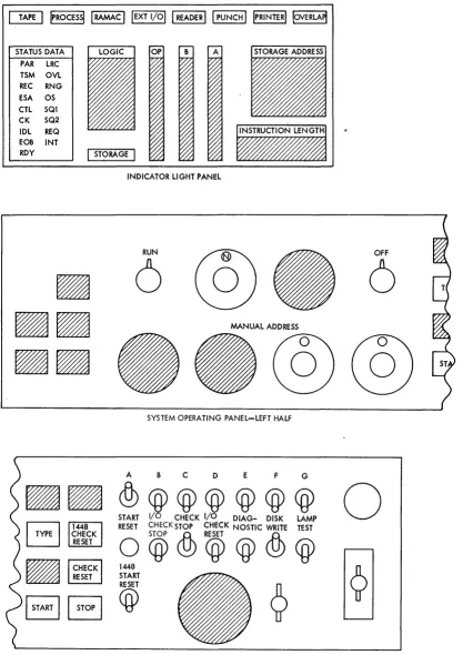
IBM 1447 Console
The IBM 1447 Console, Model 4, is a required unit in any ATS machine
configuration. In addition to the usual computer switches, the console
has Cl 1448 display panel and reset switch. In Figure 1, a diagram
of the console panel shows the proper setting of all switches for ATS
operation. 'These settings should be verified each time the operator
is near the console.
start Reset Button and 1448 Start Reset Switch
The black button marked START RESET resets the computer. This button
STATUS DATA PAR lRC TSM OVl REC RNG ESA OS CTl SQl CK SQ2 IDl REQ EOB INT
ROY
I
STORAGEI
INDICATOR LIGHT PANEL
RUN OFF
6
6
MANUAL ADDRESS
--@@
SYSTEM OPERATING PANEL-lEFT HALFA B C 0 E F G
• •
<fu@@@@@@
START I/O CHECK I/O DIAG- DISK LAMP
~ 1448 RESET CHECKSTOP CHECK NOSTIC WRITE TEST
~i~~~K
O@&>CQ)@&>@
~ 1448
~ START
I
STARTI
B
@
?
o
SYSTEM OPERATING PANEl- RIGHT HALF
[image:8.613.80.506.79.669.2]Note: Not all of the features shown will appear on the console of every system.
Immediately below the Start Reset button is a toggle switch marked
1448 Start R~set. It resets the 1448 Transmission Control Unit.
This switch should be pressed up at the same time that the Start Reset
button is pressed. It should not be touched while ATS is cycling.
Mode Selection Dial
The Mode S"election dial allows a number of diagnostic modes for
debugging and altering programs. During normal running conditions,
the dial should point straight up in the RUN position. If the switch
is not set to RUN, the computer will not cycle the ATS program.
I/O Check Stop Switch
When the I/O Check Stop switch is ON, the computer will stop if there is an error condition in the. card reader, card punch, or the line
p.rinter. If i t is OFF, the computer will continue to operate, and
the program must check for I/O errors. When ATS is running, this
s'witch should be OFF (down).
Check Stop Switch
This switch controls the response of the computer to parity errors
in core memory. If the switch is ON (up), the computer will halt
~hen a parity error occurs. If the switch is OFF (down), the computer
will not halt. In either case, the Check Reset light will be
illuminated when a parity error occurs. When ATS is running, this
s·witch should be ON (up).
Diagnostic Switch
This switch is used by the IBM Customer Engineer and should always be in the. OFF position during normal system cycling.
Disk write Switch
If the Disk Write switch is OFF, the program cannot write disk records.
When ATS is running, this switch must be ON.
Power On Switch
The Power On switch is located on the extreme right of the console
panel. This switch controls the main power supply for the entire
Emergency Pull
Located in the upper right corner of the console is a red knob marked
EMERGENCY PULL. Pulling this switch will drop power immediately, and
i t is used only in cases of emergency. If i t is pulled, the CUstomer Engineer must be called to restore i t . It should never be used for normal Power Off.
Program Load Key
On the 1447 Console of a 1440 system there is a key marked Program Load, and on the 1402 Card Read Punch of a 1460 system there is a
key marked Load. These keys are used to start a program that is read
from cards. The first few cards of such a program are a small
subprogram called a bootstrap. The Load key starts the bootstrap
program operating, i t , in turn, loads the main program into the
machine and gives i t control. Before the Load key is pressed, the
console should be "readied" (see below).
Readying the Console
Throughout this manual the phrase "Ready the Console" will be used. This means setting the Mode Selection dial to RUN, pressing the Start Reset button and the 1448 Start Reset switch (and the Check Reset key light, if i t is lighted).
NOTE: The console should be readied only when the processor is
stopped.
Some components of the system have meters with small toggle switches
marked ON and OFF. When the switch is ON, the meter for that component
will operate. When the switch is OFF, that component is unavailable
to the program. The operator should be sure all meter switches are
ON for all components used by the ATS program. The locations of meter
switches on the more important units of an ATS machine configuration are:
Machine Unit
1447 Console 1448 Multiplexer 1311 Disk Drives 1301 Disk Storage
Altering and Displaying Core
Location of Switch
Right rear of unit Side panel
Front panel, next to ON-OFF button Side panel
The 1447 Console Input/Output Printer is useful for displaying or
altering small sections of core storage. To display or alter, the
B-address register must be set to the appropriate high-order storage
address. This is done by setting the desired address on the four
address dials. The computer must be stopped and the Start Reset
button pressed. All characters printed on the typewriter or typed
into core go through the B-register. For this reason, the square key
be turned to ALTER and the Start key pressed. This will set the
address in the address dials into the B-address register. This action
communicates the location of the characters to be displayed or altered. By leaving the Mode Selection dial in the ALTER mode and pressing the Type key, any characters typed on the console typewriter will go into
core storage beginning at the indicated address. If the Mode Selection
di_al is tux,"ned to CHARACTER DISPLAY and the Type key is pressed, the contents of core storage will be typed on the typewriter beginning
at the indicated address. To return to a normal operating status,
the Mode Selection dial must be set to the RUN position.
Branching to an Address
In certain rare instances, i t will be necessary to force the computer
to start at a given address. The desired starting address is first
set in the address dials. The computer is stopped, and the Start
Reset button is depressed. The Mode Selection dial is set to ALTER.
The Instruction Address key (I ADD REG) is pressed, followed by the
Start key. This places the address from the dials into the Instruction
Address register. The Mode Selection dial should then be returned
to the RUN position. When the Start key is pressed again, the computer
will begin executing instructions beginning at the address in the
Instruction Address register.
IBM 1448 Transmission Control Unit
The 1448 Transmission Control unit is the interface between the
computer and the terminals. Each terminal is connected by a telephone
line to an adapter in the 1448. These adapters are numbered beginning
at O. Thus, if there are 40 terminals on th~ system, the Line Adapters
(lines) are numbered from 0 through 39. For convenience, the terminals
are numbered according to the lines to which they are attached.
Text coming into the system from a terminal flows through the
appropriate line into the 1448, and from the 1448 into core storage.
When a block of characters has been accumulated, i t is written to the
disk.
Line Status
The system may be rece1v1ng text, transmitting text, or neither
receiving nor transmitting on any line. The status of any attached
line may be displayed in the indicator light panel by setting the two
low-order address dials to the 1448 line number. The status of the
line will be shown by a Status Indicator light.
When the computer is receiving text from the terminal, the status is
Receive and is shown in the lights as:
REC
When the computer is transmit'ting text to 'vde terminal, the status is Transmit. and is shown in the lights as:
Whenever the program is processing a request i t set,s the status to
Control, which effectively blocks any characters typed from reaching
core storage.
This status is shown in the lights as:
CTL
The program initially instructs the
1448to accept ,characters by
setting the status of the line to Receive-Idle.
As soon as characters
arrive from the terminal, the status changes to Receive.
Whenever a
terminal opera tor hits the Attention or Carrier Retlllrn keys, the
terminal keyboard locks.
When the program sets the status to
Receive-Idle, the
1448sends the Keyboard-Unlock character -to the terminal.
Thus, after every Carrier Return and Attention, the line is set to
Receive-Idle status to unlock the terminal keyboard and prepare the
1448
to receive text.
This status is shown in the lights as:
REC
IDL
If a character with invalid parity arrives from a berminal, the
1448will change the status from Receive to Receive-Check.
This status
is shown in the lights as:
REC
CHK
If a terminal is in the offline condition (no initial Attention-U or
Attention-A action), or in certain rare peak-load cc::>nditions, the
program may not have space for the characters comin9 from the terminal.
If this should happen, the status will appear as Receive, End of
Storage Area.
A terminal in the offline condition is assigned a
four-character area.
When the fifth character is received, the status
changes to Receive, End of Storage Area.
This status is shown in the
lights as:
REC
ESA
The program must examine the status of every line attached to the
1448.
For that reason, the program must know the number of lines
attached.
The
1448has circuitry that checks the program to be certain
that it is examining all the lines that it should.
If the program
should fail in this respect, the
1448will halt the computer (Check
Reliet) and the Out of Step status will appear in
thE~lights for every
line.
This status is shown in the lights as:
OS
Whenever the
1448 requ~resattention, i t interrupts the program.
After the program exam1nes the lines, i t returns to the interrupted
instructions.
This normally occurs every tenth of a second--too fast
to show in the lights.
However, if the program is unable to interrupt,
the Request Interrupt status will show.
This status will occur if
the Stop key is pushed, if the computer is waiting for an input/output
operation, or if the computer halts. This s tatus
i~;shown in the
lights as:
1448 Control Panel
The 1448 control panel is located behind the doors at the front of
the unit. Normally, there is no reason for anyone but the Customer
Engineer to work with the control panel. However, there is one switch
of interest called the Text Time Out. Text Time Out is not used by
the ATS, and the switch must always be OFF (up) when ATS is running.
IBM 1311 Disk Drives
---
..
~-~---ATS will have from one to five 1311 Disk Storage Drives containing
removable disk packs. A disk pack consists of six disks mounted on
a spindle. Information is read or written on the disks by read-write
heads mounted on a movable access arm. The read-write heads "float"
on a slender film of air a few millionths of an inch thick. Because
of this tolerance, dust particles may ruin a disk pack. The Customer
Engineer will clean the packs and the read-write heads as part of his regular maintenance, but the operator should exercise all reasonable
care when handling the packs to avoid contamination. The packs should
be k4apt in their sealed containers or on the drives, with the drive
covers shut.
The 1311 Disk Storage Drive is started by pressing the Start-Stop key
to the left of the front window. When the disk has arrived at the
proper speed, the green light containing the drive number will be
illuminated. The disks are then ready for use.
ATS PROGRAM
The ATS program consists of a number of smaller programs, each with
its own function. A list of the ATS programs is contained in the IBM
1440/1460 Administrative Terminal System, Programmer's Manual (H20=rr228).
The Inaster program, called the Scheduler, controls the interaction
of the other functional or application programs. The application
programs are requested by the actions taken at the terminals. Each
prog:cam performs a certain type of action. For example, the COINS
program finds previously entered lines so they may be corrected. The
FRPRT program generates the output stream when a terminal requests a typeout.
Program Overlays
The j~TS is much too large to reside in core storage. It resides in
the disk storage. The application programs are read into core as
they are needed. The S.cheduler, however, is always resident in core
and decides which application programs should be read in and activated.
The main portion of all application programs is 20 sectors long on
the disk, and occupies 1,800 positions of core storage. Many of the
programs are much larger than this: their additional parts are broken
up i:nto segments ten sectors in length, called overlays. These
In the ATS all programs and overlays are designated by five-character
names. For example, Format and Print, the program that generates
output to the terminals, is called FRPRT. Its overlays are given the
first few letters of the program name plus the number of the overlay. For example, FRPRT has six overlays marked FRPR1, FRPR2, FRPRJ, FRPR4, FRPR5, and FRPR6.
Program Modifications
Whenever errors in a program are uncovered, program modifications will be sent to all ATS users registered with the IBM Program
Information Department. These modifications will n 4:>rmally be in the
form of replacement object program decks for particular programs.
The new program decks are then read onto the disk, using the procedure:s described in the section entitled "PATCHING System Parameters".
Calling Programs from Disk Storage
Once the programs have been loaded onto the disk, the card decks are
no longer necessary for normal operations. Wheneve:r a particular
program is desired, i t is called from disk into core storage by the
bootstrap program. This program is named the Call Monitor program.
It has the five-character name CALLM punched into cc:>lumns 76 through
80 of the object deck. The Call Monitor program contains its own
loader. When i t is loaded, the console Type light is turned on. The
operator may then type the name of any program in disk storage that
he wants to execute. For example, to cycle the ATS program the
operator types:
ATS
PROGRAM LAYOUT AND OPERATION
Core Storage
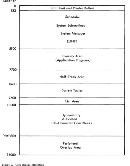
Figure 2 contains the allocation of core storage fo:l:' ATS. Positions
o
through 332 are the areas in which images are assembled for thevarious peripheral devices. Positions 1 through 80 receive card
images from the card reader; positions 101 through 180 receive card
images that will be punched into cards; positions 201 through 332
contain images for the printer. Position 81 contains an unconditional
branch that recycles the system, should a peripheral tape/printer
hang-up occur. The remaining characters in this area contain the
index registers and certain portions of the Scheduler.
The major portion of the Scheduler is located in positions 333 through
5900. The Scheduler controls and schedules the work done by ATS.
The work is performed by the application programs that are read into
the overlay area as they are needed, one program at a time. Permanent
Storage half-tracks are manipulated in the half-tra4:k area by the
application programs that work with Permanent Storage. Other
application programs use the half-track area for data or program
overlays. Tasks that are to be performed are queued in the List Area.
Location
-0
333
5900
7700
8600
9600
10000
Variable
16000
Figure 2. Core storage allocation
Card Unit and Printer Buffers
Scheduler
System Subrouti nes
System Messages
EUNIT
Overlay Area
(Appli cati on Programs)
Half-Track Area
System Tab
I
es
List Area
Dynamically
Allocated
lOO-Character Core Blocks
[image:15.613.89.529.65.627.2]A large data area, composed of blocks of 100 characters, follows the
List Area. These blocks hold the text being received from or
transmitted to the terminals. The number of blocks required depends
on the number of terminals attached to the system, and their activity.
If the number of core blocks is not too large, i t
is
possible to use the unused positions of core storage for special peripheral programs to perform card-to-tape, tape-to-printer, or similar operationssimultaneously with the operation of ATS. Two such programs are
furnished with ATS. They occupy the upper 1900 positions of core.
If they are to be used, the number of core blocks allc)wed f or terminals
must be 41 or less. In addition, programs may be writ.ten by users
in order to take advantage of their particular system configuration.
When a terminal wishes to go online to begin using thE~ system, the
Scheduler checks to be certain there are enough core blocks to
accom-modate the additional terminal. If there are not, thE~ terminal will
receive the message:
GO ON-LINE
and will not be allowed to operate. The system requiJces six free
blocks for its own use. If there are seven or more f)Cee blocks, the
Scheduler will allow the terminal online. The least number of core
blocks necessary to operate ATS is thus equal to the number of terminals
that will be simultaneously active, plus six. BecaUSE~ of hardware
considerations, the highest block may not be used as a core block.
Thus, the maximum number of core blocks that may be aBsigned
is
59.It is difficult to recommend the number of core blockB that will be
needed, since ATS applications vary widely. A rule of thumb is 1.5
core blocks per active terminal, or 59 core blocks for a 40-terminal
system. For a moderately active system, 1.25 core blc)cks per terminal
should suffice, or 50 core blocks for a 40-terminal system. Many
installations will find that all of their terminals are not active
simultaneously. Core blocks may then be allocated acc;:ording to the
number of active terminals. The operator may change the number of
core blocks being used by the system whenever necessary. The ATS
program must be shut down, a new patch card made, and the program
reloaded to accomplish this change. This procedure is described in
the section "The First Day - Preparing to Run ATS", bE~low.
Dj;,sk Storage
The 1311 Disk Storage Drives are numbered beginning at~ O. Since there
are five possible drives in anyone system, the drivefi are numbered
o
through 4. The drives are never in line according t~o number. Driveo
is always in the center, with the satellite drives placed on theleft and right.
The disk addresses ascend sequentially from the first cylinder of
drive 0 to the last cylinder of drive 4. Addresses 000000 through
019999 apply to drive O. The lowest address on drive 1 is 020000,
located at the bottom of the outermost cylinder. This progression
continues through the remaining drives, as follows:
Drive Sector Addresses C;tlinders.
0 000000 to 019999 0 to 99
1 020000 to 039999 100 to 199
2 040000 to 059999 200 to 299
3 060000 to 079999 300 to 399
Disk storage may be considered as a sequential series of cylinders. The computer accesses the drive corresponding to the sector address
speci:fied by the program. The program conveys this information through
a ten'-character field called a disk control field. This field precedes
the information to be read (written) into (from) core storage. The
disk control field to read the FRPRT program from the disk, for example, looks like this:
*000100020
The asterisk is called the drive designator. It will be an asterisk
when the sector resides on a disk pack, i t will be a right parenthesis
(or lozenge) if the sector resides on 1301 Disk Storage. The next
six qharacters of the disk control field contain the sector addiess. The final three characters contain the number of sectors to be read
or written. A read disk command which addresses the asterisk in the
above example would read 20 sectors beginning at disk sector 100. The informati.on would be read from sectors 100 to l19--a block 20 sectors long.
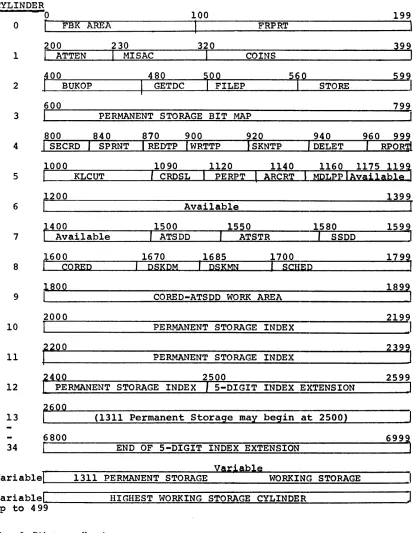
Disk Storage Allocation
Disk storage is used for five purposes in ATS: programs, data, Working
Storage, Permanent Storage Index, and Permanent Storage. Figure 3
shows the disk allocation for ATS.
The first ten cylinders hold programs and three data areas, the First Block Area, the Permanent Storage Bit Map, and the CORED-ATSDD Work Area.
The CORED-ATSDD Work Area is used for temporary storage when the CORED and ATSDD programs are operating (see "ATS utility Programs"). It may also be temporarily used by user-written programs.
Each terminal is numbered, beginning at 0 and extending through 39. Similarly numbered disk sectors are assigned as the first block for
the correspondingly numbered terminals. The First Block (FBK) for
terminal 0 is sector 0, the FBK for terminal 1 is sector 1, etc. Thus the First Block Area begins at sector 0 and extends through
sector 39. The last five characters of every FBK contain the disk
address of the first sector of Working Storage for that terminal.
If i t is blank, the terminal has no Working Storage; that is, i t is
in the offline or cleared status. The other characters in the FBK
specify the t:erminal's tab settings, page depth, and line width, to name just a few of the fields.
Permanent Storage is stored in sections of ten sectors called
half-tracks. Each bit in the Permanent Storage Bit Map corresponds to a
particular half-track of permanent storage. When a half-track is
used, its bit in the bit map is on, when the half-track is available, its bit is off.
Working Storage
Keystrokes from the terminals are written in the Working Storage
section of the disk, one sector at a time. There is no specifically
CYLINDER
o
o
DBK
AREA200
1
I
ATTEN 230I
MISAC100
FRPRT
320
COINS
199
,
399
2
~[_0_0~~~
BUKOP ____~~4~8~0~~
I
GETDC __~1_0~0~~
FILEP _______5.1._0~~~~
STORE _____ 5_9_, 799 3 PERMANENT STORAGE BIT MAP920 940
4 SKNTP DELET
1000
I
1090 CRDSLI
1120 PERPTI
ARCRT 1140 MDLppiAyai1ab19 1160 1175 1193 5I
KLCUT1399
6 Available
7
1400
I
_Available , ATSDD 1500 , 1550 ATSTR '~I~S-S-D-D--"':'::~] 1580 1599,8
1670 ,1685 1700
'PSKPM PSKMN
I
SCHEP1799
I
1899
9 CORED-ATSDD WORK AREA
2000 2199
10 PERMANENT STORAGE INDEX
J
11 ~200 PERMANENT STORAGE INDEX
2500 2599
12 PERMANENT STORAGE INDEX 5-DIGIT INDEX EXTENSION
13 ~§oo (1311 Permanent Storage may begin at 2500)
6800
34 END OF 5-DIGIT INDEX EXTENSION
yariab1e
variab1e~1
__~1~3~1~1~P~E~R~MAN~=E~N~T_S~T~O~RA~G~E~
________W~O~RK~I~N~G~S~T~O~R~A~G=E~
____ __variab1e~I ________ ~H~I~G~H~E~S~T_W~O~RK~I~N~G~S~T~O~RA~G~E~C~Y=L~IN~D~E~R~ ____________ ~J up to 499
[image:18.612.84.497.65.598.2]for all terminals begins at a specified sector address (see "Patching
System Parameters") and gradually grows downward. Each time a new
date is entered on the console (see "Normal Operations"), i t starts
a9ain at the specified address. The Working Storage of one terminal
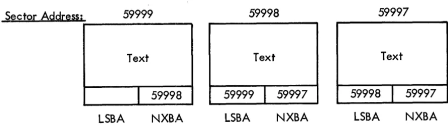
is kept separate from the Working Storage of other terminals through a chaining technique, which is also kn'own as dynamic storage allocation. Every Working Storage sector contains the disk address of the Working
Storage sector which follows in sequence. Consider a document (shown
in Figure 4) that contains enough text to fill three Working Storage
sectors. The beginning of the document would be in the sector on the
left, while the end of the document would be in the sector on the ri9ht.
Sector
Address;
59999
59998
59997
Text
Text
Text
I
59998
59999
I
59997
59998
I
59997
LSBA
NXBA
LSBA
NXBA
LSBA
NXBA
Figure 4. Working storage with two -way chaining
No·te that the last five characters of each Working Storage sector contain the address of the next sector that follows in the document
sequence. This is called the forward chaining address. The last
sector of the chain "points" to itself, which means the chaining
address of the last sector is the same as its address. Since one
sector always points to the next link of the chain, the Working Storage fo:r the terminals does not need to be sequentially assigned.
In addition to forward chaining addresses, Working Storage sectors
also contain the addresses of preceding links or sectors. The forward
chaining address is called the NXBA (Next Block Address), the backward chaining address is called the LSBA (Last Block Address).
Permanent Storage Index
Following the first ten cylinders of program and data is the Permanent
Storage Index. If five-digit document numbers are allowed, i t occupies
25 cylinders; if four-digit document numbers are used, i t occupies 2
1/2 cylinders. The Permanent Storage Index consists of four-character
entries -- one for every possible document number. If the entry is
blank, the document number is available. The four-character entry
[image:19.617.145.591.224.352.2]Permanent Storage Operation
Documents stored for later reference are located in permanent storage. The Permanent Storage area circulates between a specified upper and lower bound on disk (see "Patching System Parameters"). This area is mapped in the Permanent Storage Bit Map and its contents are
referenced in the Permanent Storage Index. When a document is deleted,
its four-position index entry is cleared and its half-tracks are made available in the bit map for future storage.
A chaining technique is also used with Permanent Storage. Instead
of chaining single sectors, Permanent Storage chains half-tracks (ten
sectors). The address of a half-track is always a multiple of ten.
Since the low-order digit is always zero, the addresses of half-tracks are stored as four digits with a low-order and a high-order zero
understood. For example, address 3255 is understood to mean 032550.
A disk control field to read or write that half-track would appear as follows:
*035550010
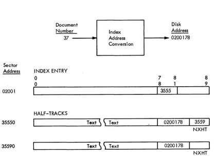
An example is shown in Figure 5.
. Sector Address
02001
35550
35590
Figure 5.
Document Number:-.
37
INDEX ENTRY 0
0
I
HALF-TRACKS
Example of permanent storage
--
Address Index ConversionText
~ ~
TextText
~ ~
TextDisk Address I---il~
0200 1 78
7 8 8 1 .
I
3555
I
0200178
0200178
8
9
I
3559
NXHT
NXHT
Permanent Storage half-tracks are chained in the forward direction
only. The last four characters of the half-track contain the address
of the next half-track in the document. This field is called the
Next Half-Track (NXHT). The seven-character field preceding NXHT
contains the sector address, and character address within the sector,
of the index entry corresponding to that document. Since this reference
[image:20.613.55.473.312.624.2]sector is understood, leaving five digits for the sector address.
Specific characters within sectors are numbered from 00 to 89. The
character address designates the high-order (the leftmost) character in the index entry.
The first sector of the first half-track of every document contains status information which appears as follows:
Character ~ress 0-49 50-53 54 55-59 60-61 62-63 64-69 70-71 72-73 74 75 76-79 80-84 85-89 Mnemonic DCID DCRL DCNM DCOT DCDC DCQH DCMO DCUN DCLW Contents
Document identification Blank
Reel character, if i t is on a Permanent Storage Tape Reel number, if i t is on a Permanent Storage Tape Number of storing terminal Blank
Date document was stored Number of half-tracks used Blank
Mode of last unit in document Blank
Number of units in document Lock word
Blank
The end of a Permanent Storage chain is indicated when the chaining address (NXHT) is blank.
Permanent Storage Index Address Conversion
A document is assigned a number at the time i t is stored. For example,
the action:
ATTN s37 CR
stores a document in what can be considered as location 37. Clearly,
th,e number 37 does not mean that particular disk sector (sector 37
is the FBK for terminal 37). The ATS program converts the number 37
to a specific disk sector address and character address within that
sector of the Permanent Storage Index. For document 37, shown in
Fiqure 5, i t is sector 02001, character 78. This location is the
address of the high-order character of the index entry corresponding
to the document. That four-character entry contains the address of
the first half-track of the document.
The address of the index entry for a document (called INBA-Index Block
Address) can be found by dividing the document number by 20. This
qUlotient,plus 02000 is the sector of the appropriate index entry.
D~~ide the remainder by 10. The character address within the index
sector is 50 times this new quotient, plus 4 times this new remainder.
0/20
=
Q and RR/IO
= q and r sector address = Q + 02000character address
=
50*q + 4*rThe conversion for document 37 is, for example:
37/20
=
1 and 17 17/10=
1 and 7sector address
=
1 + 02000=
02001 character address=
50*1 + 4*7=
78To convert an index block address (INBA) to the document number i t
represents, a reverse procedure is used. If the character address
is 50 or more, reduce i t by 10. Divide this number by 4 and add i t to 20 times the difference between the sector address and 02000.
Schematically, this computation is as follows (where s means sector
address and c means character address):
20(s 20(s
02000) + (c /4)
=
0 [if02000) + «c -10)/4)
=
D [ifc is c is
00-36 ] 50-86]
The conversion from 0200178 is, for example:
20(02001 - 02000)
+
«78-10)/4)=
D20(1) + (68/4)
=
20 + 17=
37This method of computation does not assign index entries to character
positions 40 through 49. In the first 100 sectors of the index,
character position 40 is used as a pointer for waiting messages. If
the character address of the INBA is 40, the terminal that will receive the message is indicated by the two low-order digits of the sector
address. For example, INBA
=
0200040 is the index entry for waitingmessages for terminal 0, and INBA
=
0209940 is the entry for terminal99.
Terminals 0 through 39 are normal ATS terminals. Terminals 40 through
99 are special output devices as follows:
Terminal Number
40-95 99 98 97 96
Output Device
Unassigned
Card punch (1402 or 1442)
Printer (1403 or 1443) or output tape Output tape
Upper- and lowercase chain printer or output tape
~C ATS OPERATIONS
THE FIRST DAY--PREPARING TO RUN ATS
The ATS program is very easy to activate. Only the disk packs require
preparation before loading the program decks. The operator then
describes his particular system configuration to the program, which automatically adjusts itself accordingly.
Preparing the Disk Packs
It is a good operating practice to label the disk packs. The label
should go directly on the pack, not on the cover. The pack must first
be mlounted on the drive, and the protective cover removed. Pencils
shou,ld not be used for labeling because of the temptation to erase.
The rubber from an erasure may ruin a disk pack. The best labels are
adhesive bac::ked. Each pack should be labeled with its appropriate
drive number. A sample label might be:
ATS -- Drive 0
After the packs have been mounted and labeled, the appropriate addresses
must be written. All the packs are addressed in the Load Mode in
true address format. The ATS program itself may be used to write the
addr'esses.
Normally a program has no access to the addresses written on the disk. To allow this access, the write Address key must be pressed and the
Compare Disable key lock switch turned ON. They are both located on
driv'e O.
Writing Addresses on the Drive Zero Pack
The first step in loading the ATS program is to write addresses on
the drive 0 disk pack. There are two possible procedures - one using
ATS and the other an IBM Clear Disk Utility Program (140l-UT-053 for 1460 systems or 1440-UT-041 for 1440 systems).
To u,se ATS to write addresses on drive 0, the Disk Load (DSKLD) and Scheduler (SCHED) programs should be separated from the ATS object
program deck. These programs should then be placed in the card reader,
DSKLD firsto The console should be readied and the Load key pressed.
The card reader will p~use on the last card. At this point, the
console should again be readied, Sense Switch B set ON (up) and a
manual branch to core location 5900 executed. The program will type:
on the 1447 Console Input/Output Printer. The system is told to write addresses on the drive 0 pack by typing:
WRITE 0 RELEASE
where RELEASE means press the Release key. The program will type:
'WRITE-ADDRESS' ON--INHIBIT ADDR COMPARE CHECKING
and halt. The Write Address key on drive 0 should be pressed on
(lighted) and the Compare Disable Switch turned ON. When the Start
key i& pressed, the program will write addresses on the drive 0 pack. After this is accomplished, the program will type:
RESTORE 1311 STATUS
and halt. The Write-Address key should be pressed off (unlighted)
and the Compare Disable Switch turned OFF. The pack is now ready for
loading ATS program.
If an IBM Clear Disk Utility Program is to be used to write addresses on drive 0, a control card should be punched in the following format:
~ Columns
1 2- 7 8-13 14-15
Contents
L
000000 019999 00
DATE and RDLIN cards are not required for this operation. Before
running the program, the write Address key should be pressed, the Compare Disable switch should be turned ON, and the drive started. When the drive is ready, the green light containing the drive number
will light up. The printer and console should be readied and the
program placed into the card reader with the control card at the end
of the deck. When the Load key is pressed, the program will be loaded
and the card reader will pause on the last card. The Start key must
be pressed to read i t . The program will log the information on the
control card on the printer and halt. When the Start key is pressed,
addresses will be written on drive O. Detailed operating instructions
may be found in the publications Disk Utility Programs Specifications, IBM 1401,1440, 1460 (with IBM 13or-ind 131fT (C24-1484>, and Disk utrl'Iti-pr09rams""O'Ee"ratIilci ProcedUreS';-Imri'40l and 1460 (with-rni'l and 1311) (C24-3l05) or D1Sk Ut111ty ProgramiiOperatrng-proceaure8; IBM ~-13ll, IBM l440-I!Or (C24-3121>.
---
---
---Writing Addresses on Additional Packs and Modules
Mount a new pack on drive 1, 2, 3, or 4. Turn sense switch B ON and
cycle ATS. After the message:
WHAT'S NEW?
appears, type:
WRITE i RELEASE
where I is the disk drive number on which the new pack is mounted. The remaining procedure is identical to writing addresses on drive
Cleaz' Disk utility Programs mentioned above. Writing addresses on 1301 Disk Stc)rage modules must be done with the IBM Clear Disk Utility Progz'ams.
~ing System Parameters
ATS is initially set for a minimum configuration, namely, a one-line,
one-drive 1440 system. By changing certain parameters, i t is possible
(1) t~o vary the upper and lower bounds of Permanent Storage, the upper
and l.ower bounds of Working Storage, the number of attached terminal line", the number of core blocks to be used, and the Permanent Storage Tape "write" drive, (2) to indicate the presence of a 1460 system, a 1- tC) S-module 1301, the Translate feature, a printer, a printer with
uppel~- and lowercase chain, a punch, or (3) to allow five-digit
document numbers to be used. Each change is done by adding a patch
card of a specified format immediately in front of the last card in
the COMPOOL object deck. The COMPOOL deck consists initially of eight
cards having the ID of
11111
(zero-l punches) in columns 76 through80.
HighE~st Permanent Storage Address (HPSA)
HPSA is a five-digit field (low-order zero understood) indicating the
upper bound of permanent storag·e. It comes assembled as 01500
(undE~rlined digits are wordmarked), which is interpreted as sector
015000 on the 1311. For 1311 systems i t should equal the same logical
ad.drE~ss as the Lowest Working Storage Address (LWSA). The omission of low-order and high-order zeros will make the value in the patch
card for HPSA ten times that in the patch card for LWSA. For 1301
systE~ms i t should be set to 20000 times the number of modules. (Use
~9999 for a five-module system.) The patch card format is:
Card Columns Contents
1-2 61
3 1 (11-0)
4-5 05
6 Word separator (0-5-8)
7-11 New value of HPSA
12-71 Comment: HIGH PERM STORE ADDR
72-80
040011111
Lowest Permanent Storage Address (LPSA)
LPSA is a five-digit field (low-order zero understood) indicating the
lower bound of permanent storage. It comes assembled as 00250, which
is interpreted as sector 002500 on the 1311. For 1311 systems allowing
five,-digit document numbers, i t should be set to 00700. For 1301
Card Columns
1-2 3 4-5 6 7-11 12 13-17 18-71 72-80
Contents
60
! (11-0 punch) 10
Word separator (0-5-8 punch) New value of LPSA
Word separator (0-5-8 punch) New value of LPSA
Comment: LOW PERM STORE ADDR
0400/////
Highest Working Storage Address (HWSA)
HWSA is a five-digit field (high-order zero understood) indicating
the upper bound of working storage. It comes assembled as 20000,
which is interpreted as sector 020000 on the 1311. It shouTd be set
to 20000 times the number of l3Tl drives. (Use 99999 for a
five-drive 1311 system.) The patch card format is:
-Card Columns
1-5 6 7-11 12-71 72-80
Contents
62N05
Word separator (0-5-8 punch) New value of HWSA
Comment: HIGH WORKING STORE ADDR
0400/////
Lowest Working Storage Address (LWSA)
LWSA is a five-digit field (high-order zero understood) indicating
the lower bound of working storage. It comes assembled as 15000,
which is interpreted as 015000 on the 1311. For 1311 systems i t
should be set to 20000 times the number of drives minus a constant. This constant is the total number of sectors allowed for working
storage. 5000 sectors is generally sufficient for working storage.
(For example, LWSA equals 35000 for a two-drive system.) For 1301
systems i t should be set to Q7000. The patch card format is:
Card Columns
OUtput Devices
1-5 6 7-11 12-71 72-80
contents
61N05
Word separator (0-5-8 punch) New value of LWSA
Comment: LOW WORKING STORE ADDR
0400/////
The assembled system assumes no output devices. A patch card is
required for each output device attached. These devices are given
special terroinar-numbers. For a 1403 Printer with an uppercase and
Card Columns
1-2 3 4-5 6 7 8-71 72-80
contents
63
o
(11-6 punch) 01Word separator (0-5-8 punch) Delta (11-7-8 punch)
An appropriate identifying comment 0400/////
For card-image magnetic tape (terminal 97) use the above card format,
but use P in column 3. For 48-character printout with line numbers
(terminal 98) use the above card format, but use Q in column 3. For
a ca:rd punch (terminal 99) use the above card format, but use R in column 3.
IBM .1301 Disk Storage and Five-Digit Numbers Allowed
A single indicator is used for these two functions. ATS is assembled
and distributed for a 1311 system with 9999 as the maximum document
number. If a 1301 is used for permanent storage with 9999 as the
maximum document number, punch the following patch card:
Card Columns
1-2 3
4-5 6 7 8-71 72-80
Contents
64
1 (11-0 punch) 01
Number of 1301 modules Blank
An appropriate identifying comment 0400/////
If a 1301 is present and five-digit document numbers are to be allowed
use t.he above format, but change:
Card Columns
6 7
Contents
Word separator (0-5-8 punch) Number of 1301 modules
If a 1311 system is to allow fi.ve-digit document numbers, change:
Card Columns
6 7
Contents
Word separator (0-5-8 punch) Blank
Permanent Storage Tape Drive Number
Permanent Storage Tapes may be read from any tape drive, but must be writ,ten on a particular drive. The "write" drive is assembled as
unit 1. If another unit number is desired, punch the following patch
Card Columns
1-5
6
7-71
72-80
Contents
64JOI
unit number (1 through 6)
Comment:
TAPE WRITE UNIT
0400/////
Computer Type and Translate Feature
A single indicator is used for these two functions.
ATS is assembled
and distributed for a 1440 system with no Translate feature.
If a
1440 system has the Translate feature, punch the following patch card:
Card Columns
1-5
6 7
8-71
72-80
Contents
64KOI
Word separator (0-5-8 punch)
4
An appropriate identifying comment
0400/////
If a 1460 system is used without the Translate feature, use the above
format, but change:
Card Columns
6 7
6
Blank
contents
If a 1460 system is used with the Translate feature, change:
Card Columns
6 7
Number of Attached Lines
Contents
Word separator (0-5-8 punch)
6
ATLI is a two-position field indicatinq the number of lines that the
1448 Transmission Control unit has been modified to handle.
If this
number is not known, ask the Customer Engineer.
It comes assembled
as 01, for one line.
The maximum number of lines that may be attached
is 40.
The patch card format is:
Card Columns
1-5
6
7-8
9-71
72-80
Contents
64L02
Word separator (0-5-8 punch)
New value of ATLI
Number of Core Blocks
NAVB is a two-position field indicating the number of core blocks
available for text in core.
It comes assembled for ten core blocks.
The value of NAVB should be approximately one and one-half times the
value of ATLI.
The permissible range of NAVB is
10to 59.
If NAVB
is set to a value greater than
41,the core blocks will overlap the
peripheral program area defined in ATS as assembled and distributed.
This overlap will prevent proper execution of peripheral programs
(see
,~ 1440/1460Administrative Terminal System, Programmer's Manual
(H20-0228),
for further information on this point).
The patch card
format for this parameter is:
Card Columns
1-5 6 7-8 9-71 72-80
Output Terminal Tape Drive
Contents
64N02
Word separator
(0-5-8punch)
New value of NAVB
Comment:
NUMBER OF CORE BLOCKS
0400/////
Messages for terminal
97,terminal
96with sense switch B on, and
terminal 98 with sense switch B on, are written on tape drive number
2.
On a
1460system the tape drive number may be set at the tape drive.
On a
1440system with a 7335 Magnetic Tape unit, Modell, this number
may be set by a switch on the console.
If another tape drive number
is desired in the program, a reassembly of the SECRD and SPRNT programs
is necessary.
Storage Report Tape
A request fox:' a storage report on tape will be honored only if terminal
97
has been specified as being attached, as described above.
When a storage report is written on tape, it is written on tape drive
numbe,r 2.
If another tape drive number is desired in the program, a
reassembly of the RPORT program is required.
The drive number cannot
be pa'tched in the COMPOOL.
Loading the System
After addresses have been written on drive 0 and the configuration
parameter patches prepared, the system may be loaded.
For this
program will halt with an I-address of 15957. The system is now ready for a normal start, as described in "Normal Operations" below.
NORMAL OPERATIONS
The normal duties of an ATS operator include cycling the system in the morning, requesting output during the day, and shutting down the
system in the evening. The system will service the terminals without
operator assistance.
If an ATS configuration does not have an IBM 1402 Card Read Punch or a 1442 Card Read Punch, i t is necessary that the installation have access to an IBM 1401, or 1460 Data Processing System with a card reader and an IBM 1311 Disk Storage Drive to periodically update the program pack.
Cycling the System Using the Card Reader
ATS must be called from the disk whenever i t is to be used. This is accomplished by readying the console and the disk drives, placing the
CALLM program in the card reader, and pressing the Load key. CALLM
calls the disk monitor (DSKMN) and gives i t control. SDKMN turns on
the Type light and the operator must type:
ATS RELEASE
where RELEASE means press the Release key. Dskmn will read ATS from
the dis' and give i t control. The ATS program will type:
DATE PLEASE
The date typed at this point will be used to date storage reports and
documents entered into Permanent Storage. The program will not
continue beyond this point until an acceptable date has been entered.
An acceptable date consists of a month (01-12), a day (01-31), and
two digits of a year (65-69). June 1, 1965, for example, would be
entered:
060165 RELEASE
If the date is not valid or if the Cancel key is pressed, the program will again type:
DATE PLEASE
and the date must be reentered. After an acceptable data has been
Cycling the System Using the Console
The procedure for cycling the system from the console is essentially
the same as with a card reader, except that the CALLM program must
be keyed into core storage beginning at location 15902. The program
is:
.LI9HOOlLH9I!!IlB~IOIOOll!.:!(FOI8CW!:I9HU60!!I9Bl09!:.(FllOOR§.I4G\
~I2EY~001U60lU60LllOI8B~0016850l5£bbbb*
where the wordmarked characters are indicated by an underscore.
After the CALLM program has been typed, the operator should manually
branch to position 15902 and press ehe Start key. If the program was
cor:rectly entered, the Type light will be turned on. The procedure
is -then the same as if the CALLM Program was loaded from the card reader.
~tting Down the System
The signal that shuts down the system is given from terminal O. To
perform this operation, the operator must first go online by taking the action:
ATTN U CR
followed by:
ATTN! s CR
The letter s stands for shutdown. The system will not shut down until
every waiting program has finished its work. If shutdown is successful,
control is given to the DSKMN program and the Type light will be turned on, and the operator can call the next program by typing its
name. Often this will be the ATS Document Diagnostic program (ATSDD),
described below. On a busy system the Is action may result in the
message:
ILLEGAL ACTION
The operator should repeat the action:
ATS UTILITY PROGRAMS
Permanent Storage Maintenance -- ATSDD
In order to assure the correctness of permanent storage on disk, the ATS Document Diagnostic program (ATSDD) may be run to check all
documents in permanent storage. If any errors are detected, they are
noted on the console typewriter. To use this program, ready the
console and disk drives. Set all sense switches off (down), and load
the CALLM program. (If ATS were cycling, ATTN Is CR would bring in
DSKMN instead of CALLM.) When the Type light is turned on, type:
ATSDD RELEASE
The ATSDD program is called and immediately types:
X SECTORS USED FOR WORKING STORAGE ON Y
where X is the sector total and Y is the date. This message is omitted
if ATS is not used between ATSDD runs.
The permanent storage diagnostic phase comes next. If a document is
in error and cannot be repaired, ATSDD will delete the document and type:
DOCUMENT X **DELETED**
where X is the document number. This document must later be retrieved
from the backup tape or disk (see below for backup procedures).
If part of a document falls below the lowest permanent storage address (LPSA) or above the highest permanent storage address (HPSA), the message:
DOCUMENT X OUT OF BOUNDS (Y)
is typed where X is the document number and Y is the half-track out
of bounds. The document is not deleted. This situation may be
remedied by updating the document (Get, Delete, and Store) when ATS is cycling.
If ATSDD is run before ATS deleting has been completed, ATSDD completes the deleting process and types:
DELETE CHAIN CLEARED
Since there must be a one-to-one correspondence between bits on in the Permanent Storage Bit Map and half-tracks used for documents, and a one-to-one correspondence between bits off in-tne bit map and half-tracks available for permanent storage, i t is likely that correspondence
will not ex~st 1f any of the diagnostic messages have appeared. ATSDD
always forces a correct bit map, updates i t on disk, and if i t differed from the original bit map, types the message:
X HALF-TRACKS MADE AVAILABLE
The messagell
Y HALF-TRACKS PREVENTED FROM USE
where Y is a number, is typed if bits were turned on in the original
bit map. The larger the two numbers become, the more serious the
problem in permanent storage. The last phase of ATSDD types:
X HALF-TRACKS AVAILABLE FOR PERMANENT STORAGE
wheJ::'e X is the total number, and returns control to the DSKMN program. Anot,her program may then be called by typing its name on the console typewriter when the Type light is turned on.
~lanent Storage Backup
Since i t is possible for both the ATSDD program and terminal operators to delete documents that may still be needed, a backup of permanent
storage is recommended. In addition to diagnosing permanent storage
with the ATSDD program, i·t will write a backup tape of documents on
disk. To use this option, ready the console and disk drives, and
plac:e a scratch tape on the drive used for writing archive documents. This tape drive is initially set for unit 1, but may have been altered.
(See the section "Patching' System Parameters".) Load the CALLM program and set Sense Switch B ON (up) for a backup of all documents stored that particular day, or Sense Switch C ON (up) for a backup of all
documents that currentry exist in ATS. When the Type light is turned
on, type:
ATSDD RELEASE
After the working storage sector total has been typed, the message:
TODAY'S PERMANENT STORAGE ON TAPE
will be typed if sense switch B is on, or
ALL PERMANENT STORAGE ON TAPE
will be typed if sense switch C is on. In addition to writing the
backup tape, all of the Permanent Storage diagnostics will still be
performed. The backup tape will be
![Crystal structure of (±) 3 [(benzo[d][1,3]dioxol 5 yl)methyl] 2 (3,4,5 trimethoxyphenyl) 1,3 thiazolidin 4 one](data:image/gif;base64,R0lGODlhAQABAIAAAP///wAAACH5BAEAAAAALAAAAAABAAEAAAICRAEAOw==)