White Rose Research Online
[email protected]
Universities of Leeds, Sheffield and York
http://eprints.whiterose.ac.uk/
This is the published version of an article in
Physical Review E: Statistical,
Nonlinear, and Soft Matter Physics, 88. 023023
White Rose Research Online URL for this paper:
http://eprints.whiterose.ac.uk/id/eprint/76360
Published article:
Castrej´on-Pita, JR, Kubiak, KJ, Castrej´on-Pita, AA, Wilson, MCT and Hutchings,
IM (2013)
Mixing and internal dynamics of droplets impacting and coalescing on
a solid surface.
Physical Review E: Statistical, Nonlinear, and Soft Matter
Physics, 88. 023023. ISSN 1539-3755
Mixing and internal dynamics of droplets impacting and coalescing on a solid surface
J. R. Castrej´on-Pita,1K. J. Kubiak,2A. A. Castrej´on-Pita,1M. C. T. Wilson,2and I. M. Hutchings1
1Department of Engineering, University of Cambridge, 17 Charles Babbage Road, Cambridge CB3 0FS, United Kingdom 2School of Mechanical Engineering, University of Leeds, Leeds LS2 9JT, United Kingdom
(Received 5 June 2013; published 26 August 2013)
The coalescence and mixing of a sessile and an impacting liquid droplet on a solid surface are studied experimentally and numerically in terms of lateral separation and droplet speed. Two droplet generators are used to produce differently colored droplets. Two high-speed imaging systems are used to investigate the impact and coalescence of the droplets in color from a side view with a simultaneous gray-scale view from below. Millimeter-sized droplets were used with dynamical conditions, based on the Reynolds and Weber numbers, relevant to microfluidics and commercial inkjet printing. Experimental measurements of advancing and receding static contact angles are used to calibrate a contact angle hysteresis model within a lattice Boltzmann framework, which is shown to capture the observed dynamics qualitatively and the final droplet configuration quantitatively. Our results show that no detectable mixing occurs during impact and coalescence of similar-sized droplets, but when the sessile droplet is sufficiently larger than the impacting droplet vortex ring generation can be observed. Finally we show how a gradient of wettability on the substrate can potentially enhance mixing.
DOI:10.1103/PhysRevE.88.023023 PACS number(s): 47.55.db, 47.80.Jk
I. INTRODUCTION
Coalescence and mixing of droplets on a solid surface are of great interest not only to the established inkjet printing industry but also to emerging applications such as the noncontact printing of functional electronics and biological materials and in the fields of microfluidic devices, microchemistry, and fast prototyping [1–5]. The advantages of the inkjet printing of liquid materials over traditional delivery techniques are many and based on the technological ability of printheads to generate homogeneously sized droplets on demand at a determined speed and direction. These characteristics create a scenario where precise volumes of reagents and/or reactive components can be dispatched at a specific location at precise times. The process of noncontact printing involves the generation, deposition, and coalescence of droplets to make patterns for graphics applications or three-dimensional structures in other manufacturing processes [6]. In graphical applications, the coalescence of droplets on a substrate needs to be controlled to reduce pixelation and increase the resolution of printing. In contrast, in additive manufacturing applications such as in the synthesis of nylon 6in situvia inkjet printing of reactive fluids, good mixing during drop-on-drop deposition is essential [7].
For printing applications, it is the coalescence and mixing of consecutively printed droplets (i.e., the impact of a falling droplet onto a sessile droplet) that is of particular importance. Regardless of this, most previous studies in droplet deposition have focused only on the external dynamics—e.g., the free-surface shape, extent of spreading, and final footprint of the composite droplet [8–13]—and only a few works have explored the internal dynamics or mixing [5,7,14,15].
Castrej´on-Pitaet al.[14] used particle image velocimetry (PIV) within millimeter-size droplets to observe the internal fluid velocity field during the coalescence of a sessile droplet and an impacting one. Yanget al.[5] explored the movement of fluorescent particles during evaporation of a composite droplet formed from two consecutively printed droplets, focusing on particle deposition dynamics. Both of the above works relied on viewing the coalescence process from below and using
transparent droplets, so (in the case of PIV) seeding particles could be identified and analyzed to compute the internal flow. Due to the statistical nature of the PIV algorithms, the method does not rely on the identification of individual tracking particles or fluid features and, therefore, the study of mixing is impossible with that technology. The PIV flow visualizations were also limited essentially to one plane within the flow.
In developing reactive inkjet printing for polyurethanes, Kr¨ober et al.[15] used a fluorescent dye and confocal laser scanning microscopy to assess the chemical reaction produced by drop-on-drop deposition of two reagents. No gradients in concentration were observed, leading to the conclusion that complete mixing was achieved. However, the dynamics of the reaction or mixing could not be observed. Similarly, Fathi and Dickens [7] have recently investigated drop-on-drop deposition of reagents necessary for polymerization of nylon 6 within inkjet deposited droplets. Following difficulties in achieving individual drop-on-drop placement, they explored the local mixing of components by jetting multiple droplets to form larger drops. They viewed the system from directly above, using fluorescence to assess the lateral extent of mixing assuming that the liquid is well mixed in the vertical direction. Based on this approach they concluded that a high degree of mixing (more than 80%) was achieved, with unmixed regions confined to the edges of the contact area, but, again, the visualization was not able to reveal the three-dimensional dynamics of the “interface” between the two liquids being mixed.
[18–22]. An extensive experimental study of binary midair drop collisions in air was conducted by Ashgriz and Poo [17], who characterized different regimes of coalescence and separation in terms of Weber number and an impact parameter measuring the degree to which the drop centers were offset from a head-on collision. Since one of the drops was dyed, this study also revealed that for offset collisions, substantial mixing can occur within the combined drop as a result of the free-surface deformations. These processes illustrate the potential for promoting mixing within a composite droplet.
When one or both droplets is in contact with a solid surface, coalescence is complicated by the dynamics of the three-phase contact line, particularly as a result of contact angle hysteresis [14]. Yet the initial stages of sessile droplet coalescence still represent a dramatic change in free-surface shape that produces an internal flow pattern within the composite droplet. In millimeter-sized systems, this flow is short lived, decaying within hundreds of microseconds, and the following dynamics are governed only by diffusion [23]. Previous studies of mixing driven by free-surface movement [24–26] have shown that free-surface dynamics can be effective in enhancing mixing within the enclosed liquid, even under conditions where molecular diffusion is negligible. However, the success of such chaotic advection-driven mixing or stirring relies on repeated stretching and folding of the “interface” between the two liquids being mixed. In “pure” surface-tension driven sessile droplet coalescence, i.e., where the two sessile droplets are not driven into each other by other means, there is no repeated stretching and folding, and experiments on such a system have not shown effective mixing [2]. On the other hand, in sessile droplet coalescence where one droplet is driven into the other by a wettability gradient [23], stretching and folding of the “interface” can occur, resulting in “fingers” of each liquid penetrating the other and an enhancement of the mixing.
This work explores the mixing of two coalescing droplets where one droplet is driven into the other by the impact of a falling droplet onto a sessile one. The process is studied experimentally and numerically in terms of lateral separation between the droplets, droplet size, and impact speed. We aimed to separate the effects of other variables such as drying, curing, and density and viscosity gradients from purely dynamical effects. To provide a clear picture of the mixing, the approach of coloring one of the droplets, which has been useful in visualizing the mixing during in-air coalescence of two free droplets [17] and two sessile droplets [23], is applied. The experimental results are compared with numerical simulations by the lattice Boltzmann method showing that mixing is not achieved within the combined volume of the coalescing droplets. It is also shown that mixing is not affected by the lateral separation between the sessile and the impacting droplet. Simulations are also used to predict the mixing of droplets under conditions not explored by experiments. Details of the experimental and computational methods are given in Secs. IIandIII, respectively, the results are presented in Sec.IV, and conclusions are drawn in Sec.V.
II. EXPERIMENTAL DETAILS
Two droplet generators were used to eject differently colored droplets whose viscosities and densities, surface
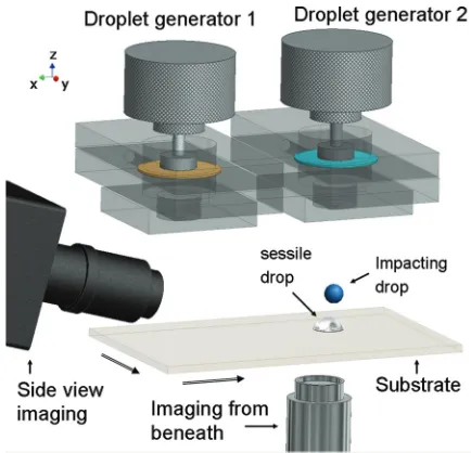
FIG. 1. (Color online) Schematic diagram of the two-droplet generator system. The generator on the left contains an uncolored mixture of glycerol and water and the one on the right contains a blue-colored mixture.
tension, contact angle, and hysteresis were carefully matched. The liquids used for these experiments were chosen in such a way that both the sessile and the impacting droplet are, from the fluid dynamical point of view, identical. The impact, coalescence, and relaxation of the droplets were recorded by color high-speed imaging to allow the identification of regions of fluid with different colors.
The design of the droplet generator has been presented elsewhere [27,28]. Briefly, it consists of a reservoir with a base containing a nozzle orifice and an upper boundary formed by a flexible rubber membrane. Droplets are ejected by the action of an electromagnetic actuator (V200, LDS Test and Measurement Ltd, UK) on the upper membrane. The actuation occurs in response to an electrical signal (waveform), the shape of which can be modified to vary the jetting characteristics. In these experiments, the drive waveform consists of a single pulse whose amplitude and width were adjusted to produce single droplets of different sizes and speeds.
The schematic view of the experimental setup is shown in Fig. 1. Two identical droplet generators were positioned with their nozzles 100 mm apart. The droplet generators with 2.2-mm-diameter nozzles with 45◦ conic inlets were driven independently by two pulse generators [28]. Below the droplet generators, a plane transparent polymer substrate (polymethylmethacrylate, PMMA, Perspex) was mounted on a translation stage.
[image:3.608.324.541.70.279.2]of incidence and the position of the lamp were chosen to maximize the contrast and brightness in both views. In this way, the light entered obliquely to the substrate to provide illumination to both systems. The color camera was coupled to a Tamron macro AF90 lens at maximum aperture and set to record at a frame interval of 1 ms with a frame exposure of 400μs; under these conditions, a resolution of 65±0.4 pixels/mm was achieved.
The gray-scale camera was used with a Navitar 12×
microscope lens system and set to record at a frame interval of 3.33 ms and frame exposures of 3.33 ms; the resolution of this system was 56.8±0.6 pixels/mm. Resolution and frame speed are competing characteristics in most single-sensor high-speed cameras. In this work, the resolution of the side-view images was prioritized over their frame speed and over the characteristics of the visualization from beneath the substrate. Both cameras were focused on the impact and coalescence zone on the substrate beneath the second droplet generator. In this way, the jetted droplet produced by the second generator impacted at the center and in the focal plane in both fields of view. Spatial or directionality accuracy (reproducibility) of the drop generators was measured to be<200μm.
During the experiments, the first generator was used to deposit, by jetting, the droplet that later became sessile on the substrate. Droplets were jetted using a drive waveform of a single square pulse whose amplitude was varied to adjust the desired droplet speed. The pulse duration and amplitude were adjusted within the range of 5.0 to 6.5 ms and 15 to 20 mbar to produce single droplets without satellite drops from both generators. In previous work with a similar system, it was shown that the internal liquid dynamics and surface retraction are completely damped within the first half-second [14]. After landing, a resting time of 5 s was used to ensure that the first droplet had stopped spreading and retracting. After this time, the deposited, now sessile, droplet was moved by means of a 2-axis translation stage to the impact zone beneath the second droplet generator. The position of the sessile droplet was then adjusted by aligning its edges to pre-established fiducial pixel coordinates on both camera views. The separation between the impacting and the sessile droplet (y axis) was adjusted by a micrometer-driven stage.
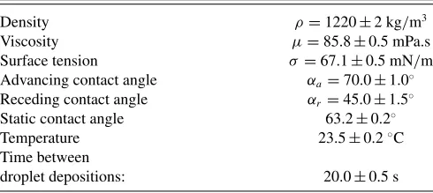
[image:4.608.312.553.72.153.2]The properties of the colored and uncolored glycerol-water mixtures were measured and adjusted to produce a system with no interfacial gradients of density, viscosity, or surface tension. The fluid properties are shown in TableI.
TABLE I. Fluid and droplet properties for colored and uncolored mixtures.
Density ρ=1220±2 kg/m3
Viscosity μ=85.8±0.5 mPa.s
Surface tension σ =67.1±0.5 mN/m
Advancing contact angle αa =70.0±1.0◦
Receding contact angle αr=45.0±1.5◦
Static contact angle 63.2±0.2◦
Temperature 23.5±0.2◦C
Time between
droplet depositions: 20.0±0.5 s
FIG. 2. (Color online) Contact angle hysteresis analysis showing advancing and receding contact angles of a drop on an inclined PMMA surface just starting to slip. The image shows a comparison of experimental measurement and numerical modelling of an uncolored mixture of glycerol and water with a viscosity of 85.8 mPa s. The droplet starts to slip when the surface is inclined at approximately 25◦.
All experiments were carried out at 23.5±0.2◦C. Liquid densities were measured by weighing a 100-ml measured volume of liquid on a precision balance (Sartorius BP211D). Fluid viscosities were measured with a vibrational viscometer (Viscolite 700, Hydramotion Ltd.) before and at the end of experiments with consistent results. Surface tension was measured with a bubble tensiometer (SITA t-15) at a bubble lifetime range of 15 to 5000 ms. The dye used to color the liquid in the second drop generator was a synthetic blue food coloring solution containing E132 indigo carmine dye, glycerol, and water (Silver Spoon, UK). The colored mixture was produced by adding 3 ml of the dye (with a viscosity of 388.0± 0.5 mPa s) to a 100-ml sample of the uncolored solution. Pure water was then added to the dyed solution until the viscosities of the colored and uncolored fluids were matched.
The liquid-substrate interaction was characterized by the measurement of the equilibrium contact angle and the contact angle hysteresis, using a similar method to that in Ref. [29]. A shadowgraph system was used to illuminate, from behind, sessile droplets resting on a substrate mounted on a rotational stage. Equilibrium contact angles were imaged with the substrate horizontal. Receding (αr) and advancing (αa) contact angles were recorded by tilting the substrate up to the first point of slip; an example of this is shown in Fig.2. From the image analysis of these recordings, the contact angles were calculated by linear and polynomial fitting. The same methodology was used on both fluid solutions (colored and uncolored). No difference, within experimental error, was observed in the contact angles for the colored and uncolored droplets.
III. SIMULATION METHOD
[image:4.608.49.294.644.754.2]the impact and spreading of droplets are particularly sensitive to the dynamic contact angle behavior. Yokoiet al.[33] found that accurate dynamics could be achieved only when using a dynamic contact angle based on experimental observations.
In contrast, the lattice Boltzmann method used here does not require the dynamic contact angle to be specified. Instead, the wetting characteristics of the solid surface are included only through the static contact angle, and the dynamic behavior emerges during the simulation. This makes the method par-ticularly suitable for the asymmetric, fully three-dimensional coalescence configuration considered here, since the dynamic contact angle varies continuously around the whole perimeter defined by the contact line. Of course, real surfaces do not in general exhibit a unique static contact angle; indeed, contact angle hysteresis plays an important role in determining the final composite droplet footprint. Hence, the model used here includes hysteresis and its inputs are only the advancing and receding static contact angles rather than the dynamic contact angle that varies widely and must be specified at all points along the contact line (as in VOF). In this work, the static contact angles were measured experimentally by using a tilted substrate, as described in Sec.II. Once calibrated by simulating this experimental arrangement to produce the correct angles (see Fig.2), the model is used without any further adjustment to simulate the droplet impact and coalescence.
Rather than solving the Navier-Stokes equations by conven-tional direct discretization of the partial differential equations, the LB approach is based on a velocity space discretization of the Boltzmann equation in which molecular velocities are represented by a set of (typically in 3D) 19 microscopic velocities,ea (a=0, . . . ,18). Theea are given by the zero vector and the vectors connecting each node to its 18 nearest neighbors in a cubic lattice structure, and each has associated with it a probability distribution function,fa. The macroscopic fluid density,ρ, and velocity,u, at each lattice node are found from moments of the distribution functions,
ρ =
18
a=0
fa and ρu=
18
a=0
faea. (1)
The dynamics of the flow emerge as the values of fa across the whole lattice evolve following a two-step process at each time step: (i) relaxation towards a local Maxwellian equilibrium distribution, capturing the effect of molecular collisions, and (ii) “streaming,” in which the value of each famoves along its associated vector to the neighboring node. Using a single relaxation time,τ, which is related to the fluid kinematic viscosity, the process can be written as
fa(x+ ea, t+t)=fa(x, t )−[fa(x, t )−f eq a (x, t )]
τ , (2)
where the local Maxwellian equilibrium distribution is given by
faeq(x, t )=waρ
1+3ea· u
c2 +
9 2
(ea · u)2
c4 −
3 2 u2 c2 (3)
fora=0, . . . ,18. Herewa are weights associated with each vectorea,xis the position within the lattice, t the time,t the time step, andcthe lattice speed. Using a multiple-scale
analysis, it can be shown that the Navier-Stokes equations can be obtained from the lattice Boltzmann equation [34].
There are various means of modeling multiphase flow using the LB framework, e.g., Refs. [35–37]. In this work the Shan-Chen [38] model is used since it was found to give the closest qualitative agreement with the free-surface shapes seen in the experiments. This efficient model introduces an interaction potential between neighboring lattice nodes, which can be expressed as
F(x, t )= −Gψ(x, t ) 18
a=0
waψ(x+ ea,t)ea, (4)
where F is fluid-fluid interaction force, Gis an interaction strength parameter (negative for particle attraction), andψis a potential function that depends on density,
ψ(ρ)=ρ0[1−exp(−ρ/ρ0)], (5)
where ρ0=1. This model produces a nonideal equation of state supporting the coexistence of a heavy phase of densityρh and a light phase of densityρl. However, use of this equation of state limits the density ratio between the heavy and light phases to about 100 and results in large spurious currents at the liquid-gas interface that hamper the tracking of passive tracer particles in this region. Here, following previous work [39,40], the Carnahan-Starling equation of state,
p=ρRT1+bρ/4+(bρ/4)
2−(bρ/4)3
(1−bρ/4)3 −aρ
2, (6)
is used (with parameters a=1, b=4, and R=1) to ex-tend the density ratio to 525 (G= −0.0553,ρh=0.43112, ρl =0.0008196668) and reduce the spurious currents at the interface while keeping the simulation stable.
Further increase of the density ratio led to instabilities and simulation failure, but further increase was deemed unnecessary since the simulation predictions were insensitive to density ratio atρh/ρl =525. Two relaxation times,τh=1.0 andτl =0.6, for the heavy and light phases, respectively, are used to capture the different viscosities of the phases, and a linear interpolation based on local density value is used to calculate the relaxation time locally at every lattice node. Setting the lattice spacing atdx=6.071×10⁻⁵m and time step asdt=4.0×10⁻⁵s produces a kinematic viscosity ratio ofνh/νl=4.741.
The wetting characteristics of the substrate are incorporated by specifying an artificial fluid density,ρs, at the solid surface, such thatρl ρsρh[41,42]. This produces an equilibrium contact angle between zero and 180◦ measured through the heavy phase. For convenience the surface density is defined in terms of a normalized “wetting parameter,”
η= ρs−ρl
ρh−ρl, (7)
soη=1 corresponds to equilibrium angleαe=0◦andη=0 toαe=180◦. Such specification of an artificial fluid density at the solid wall will generate an adhesion force at the solid-fluid interface through the multiphase model(4).
droplets [14], and hysteresis is included here using a method similar to that in Ref. [14]. Initially, the value of η=0.44 on the unwetted solid surface is set to correspond to an equilibrium angle equal to the advancing static contact angle, αa, found experimentally. Parts of the surface that become wetted then have their value of η=0.61 modified to correspond to the experimentally determined receding contact angle. Making the change inηover a controllable time scale also allows the effects of surface adhesion saturation times [43] to be incorporated. When a wetted part of the surface is dewetted, the surface density returns to its original (advancing contact angle) value over a controllable time scale. Since ρl ρsρh, the wetted/unwetted parts of the solid surface can be identified by the gradient of density normal to the surface, with∂ρ/∂n >0 corresponding to a wetted patch and∂ρ/∂n <0 to an unwetted part.
The hysteresis model was calibrated by simulating the tilted substrate experimental arrangement used to measure the contact angle hysteresis and ensuring that the advancing and re-ceding contact angles matched those measured experimentally. A plot showing the resulting droplet on the inclined surface is given in Fig.2. To analyze the internal flow evolution during droplet coalescence, passive tracer particles were followed using trilinear interpolation of the velocity field from the eight nearest nodes at each time step. Particles were initially seeded uniformly throughout the droplets.
IV. RESULTS
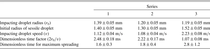
Three series of experiments were carried out to explore the coalescence and mixing under various dynamical regimes. Lateral drop separation, drop size, and impacting speed were varied within the capabilities of the system. Only conditions which produced single droplets from the generators were used. TableIIsummarizes the details of these experiments.
Under these conditions, the system can be dynamically characterized by the Reynolds (Re=ρr0v/μ), Weber (We= ρr0v2/σ), and Ohnesorge (Oh=√We/Re) numbers of the impacting droplet. Experimentally, these numbers lie in the following ranges: Re=20–23, We=29–33, and Oh=0.25– 0.26. These dimensionless numbers were chosen to lie within the operating parameters found in most commercially available inkjet printers, e.g., for typical inkjet printing systemsρ ≈ 1000 kg/m3, r
0≈50 μm, v=5 m/s, μ=10 mPa s, and σ =45 mN/m. It has been demonstrated that the behavior of impacting droplets of different sizes and temporal scales can be compared using the dimensionless time to reach the maximum spreading diameter and by scaling the time by 2r0/v, [44].
These scaling parameters are shown in TableIIto facilitate the comparison with other systems.
In addition to variation of the drop size and speed, the droplet separation was varied from axisymmetric impact conditions (i.e., zero separation) to a lateral separation of 4 mm from drop center to drop center.
A. Internal views of equal-size droplets merging
Figure3presents experimental images of a colored droplet impacting at 1.12±0.04 m/s onto an uncolored sessile droplet. Timet =0 is taken to be the moment of first contact of the droplets. The first sequence corresponds to the axisymmetric case, where the center of the impacting droplet lies directly above that of the sessile droplet. As can be seen, the impact produces a large disturbance to the free surface as the combined droplet flattens and spreads out into a pancake shape. Att= 5 ms spreading of the combined droplet has reached its full extent, and at this point the colored and uncolored parts appear to have been completely mixed. However, this is not the case, as later frames show the recoil of the free surface and reveal that no intermixing of the initial droplets has occurred. The substantial disturbance to the free surface clearly produces a stretching of the “interface” between the colored and uncolored regions, but, crucially, there is no folding of this interface on itself. Repeated stretching and folding of the interface is the basis for mixing enhancement via chaotic advection. Without folding of this interface, when the combined droplet recoils, the interface shrinks again to reach the final lenslike shape of the larger sessile droplet. At much later times, molecular diffusion drives a slow intermixing of the colored and uncolored parts.
The lower image sequences show the impact and coales-cence process when the center of the impacting droplet is laterally displaced with respect to the center of the sessile droplet. For droplet separations of 1 mm and 2 mm, the free surface is again substantially disturbed, but one can now clearly see that the impacting droplet simply pushes the liquid in the sessile droplet ahead of it as it spreads. The uncolored liquid resists this, as the contact line at the left of the combined droplet does not move, but again the internal boundary of the colored liquid is not folded over, and the colored and uncolored regions remain distinct as the final shape is reached. If the sessile droplet contact line could be driven into the combined droplet (for example, by a wettability gradient [23]) while the impacting droplet spreads above it, then folding of the interface between the droplets could occur.
[image:6.608.92.514.654.754.2]Under the dynamic conditions and offset alignment of these experiments, the collision of two free droplets would produce
TABLE II. Experimental conditions explored in this work.
Series
1 2 3
Impacting droplet radius (r0) 1.39±0.05 mm 1.20±0.05 mm 1.19±0.05 mm
Initial radius of sessile droplet 1.40±0.05 mm 1.30±0.05 mm 1.52±0.05 mm Impacting droplet speed (v) 1.12±0.04 m/s 1.08±0.04 m/s 2.23±0.08 m/s Dimensionless time factor (2r0/v) 2.48±0.18 ms 2.22±0.17 ms 1.07±0.08 ms
FIG. 3. (Color online) Color high-speed imaging of the impact and coalescence of an uncolored sessile and an impacting colored droplet. In these experiments, the impact speed is 1.12±0.04 m/s (Series 1 in TableII).
a degree of mixing within the combined droplet [17] as it spins, stretches, and oscillates due to the asymmetric contact. Here, the presence of the substrate inhibits this motion, and the deformation of the free surface is further restricted by the dynamics of the moving contact line. Hence, there remains a sharp interface between the dyed and undyed liquids and no mass transfer between the original droplets.
In all cases the final combined droplet shape is the same as that obtained without coloring the impacting droplet. Also, as expected, increasing the droplet separation results in the colored part of the final, combined droplet being located further to the right.
The droplet separation of 4 mm (lowest row of images) approaches the maximum separation at which coalescence is still possible. Under these conditions the disturbance of the sessile droplet is small, apart from the formation of the neck between the droplets, as in the coalescence of two sessile droplets. It therefore is not surprising to see the colored and uncolored parts of the droplet remaining separate.
The lack of mixing during droplet impact and coalescence is beneficial for graphical printing applications where good color separation is required. However, this could be problematic for applications where the mixing of components or color is desired—particularly for droplet-based chemistry [45], where
[image:7.608.114.490.70.306.2] [image:7.608.86.520.506.726.2]FIG. 5. (Color online) Internal flow analysis of sessile and impacting droplet during spreading phase using lattice Boltzmann simulations. The configuration corresponds to experimental Series 2.
good mixing is essential. The observations here indicate that under the conditions explored homogeneous mixing is not achieved by drop deposition and coalescence. Future work on this topic could include the parametric study of droplet mixing in terms of liquid and substrate properties to assess under which conditions the conclusions drawn by Kr¨oberet al. are appropriate [15]. However, from the observations in this work, it is important to note that having only a top view of drop-on-drop deposition is not enough to evaluate mixing and that a side view is necessary.
B. Coalescence of different-sized droplets
Figure4 shows a second series of experiments in which the impacting droplet volume is a little smaller than that of the sessile droplet (Series 2 in TableII). The impact speed is nominally the same as in Fig. 3. The images show that the behavior is qualitatively the same as for equal-sized droplets, and, again, no folding of the “interface” between the colored and uncolored liquids is seen. The side-view imaging proved to be invaluable as use of a top view would wrongly suggest that mixing was achieved.
The same effect is seen in the particle-based visualization produced by the lattice Boltzmann simulations (see Fig.5), where the passive tracers remain separated. The simulations show good qualitative agreement with the experiments in terms of the internal and external dynamics, though there is a small discrepancy in the time. Such temporal discrepancies have been observed before [46] and arise as a result of the computational liquid-gas interface thickness being larger than in practice. At later times in the simulations, as the droplet begins to recoil, the surface of the impacting droplet stops moving downwards and begins to move upwards. During this change of direction, the normal velocity of the liquid-gas interface is very small and spurious currents in the liquid-gas interface that are normally negligible compared to the average fluid velocity result in a small displacement of the tracer particles away from the interface. As the interface then accelerates upwards, a small region adjacent to the interface
is left devoid of tracers. Tracers in the bulk of the combined droplets are unaffected.
If the size of the impacting droplet is reduced significantly further, it is possible to reach conditions under which a vortex ring is generated when the small droplet is pulled into the larger one. This is illustrated by the numerical simulation in Fig.6, which shows the first stages. This effect is well known [16] and produces an extended “interface” between the two bodies of liquid, thus assisting later diffusion-driven mixing of the two droplets, at least in part of the composite droplet. However, the effect soon dissipates and again produces no active stretching and folding of the outer boundary of the colored “blob.” This mechanism is relevant to the experiments of Fathi and Dickens [7], where small drops of a second reagent are deposited on a large drop of another reagent (which was built up by printing multiple small droplets) and supports their conclusion that their reagents are mixed. However, the results of Figs.3and4indicate that, under the conditions used in the present experiments, if reagents are combined via individual drop-on-drop deposition, then mixing will be very poor.
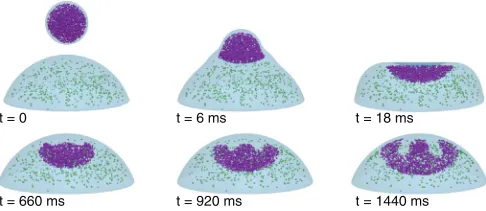
Figure7 shows the side view of further experimental se-quences in which the impact speed is approximately doubled. Here, the disturbance of the free surface during coalescence is correspondingly more violent. In particular, att ≈3 ms the
t = 0 t = 6 ms
t = 660 ms t = 920 ms t = 1440 ms
t = 18 ms
[image:8.608.74.537.76.268.2] [image:8.608.313.556.611.717.2]FIG. 7. (Color online) Color high-speed imaging of the impact and coalescence of an uncolored sessile droplet and an impacting colored droplet. These experiments corresponds to Series 3 in which the impacting droplet has approximately twice the speed of the one in Series 1.
colored liquid lamella almost spills over the left-hand side of the uncolored liquid. Such a spillover could result in the entrainment of a finger of uncolored liquid into the colored liquid, hence, folding over the “interface” between these two regions. However, increasing the speed further to achieve this effect is likely to promote splashing and loss of control of the composite droplet footprint, which in a printing application would be undesirable. As can be seen in Fig. 7, despite the increased free-surface distortion during coalescence, the end result is a composite droplet incorporating two separate volumes of liquid corresponding to the initial droplets.
C. Evolution of droplet contact area
As outlined above, the experimental arrangement allows for a simultaneous view of the coalescence process from underneath. This is particularly useful for exploring the final footprint of the composite droplet, which is important in manufacturing applications where a continuous printed track is desirable.
Figure8shows the bottom-view sequences corresponding to experimental Series 1 (see TableI). As has been observed before [14], the composite droplet has an elongated shape, as contact angle hysteresis eventually halts both the retraction of the contact line at the extremes of the composite droplet and the expansion of the “neck” region when the initial droplet separation is large. The elongated shape of the composite droplet further illustrates the damping effect that the substrate has on the free surface movement and, hence, the scope for mixing within the combined droplet.
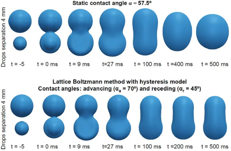
[image:9.608.81.526.71.235.2]To illustrate the importance of capturing contact angle hysteresis correctly, Fig.9shows the evolution of the droplet footprint predicted by the simulation with and without contact angle hysteresis. In the upper sequence, a single equilibrium contact angle is used, whose value is set to the average of the experimentally measured advancing and receding contact angles, whereas in the lower sequence the correct advancing and receding angles are used. During the initial spreading phase of motion, there is little difference between the two sequences, though it can be seen that the neck width develops more slowly with hysteresis included. As the droplet reaches its
[image:9.608.85.525.538.717.2]FIG. 9. (Color online) Evolution of the dynamic contact line modelled by lattice Boltzmann method without (upper sequence) and with (lower sequence) contact angle hysteresis model. The configuration corresponds to Series 2.
maximum extent and starts to retract, the effect of contact angle hysteresis is very apparent: without it, all composite droplets will eventually reach a circular footprint, whereas in practice the contact line becomes pinned. Note that the rightmost image in each sequence corresponds to the final state.
The sensitivity of the composite droplet footprint to the contact angle hysteresis makes this system a good test for the hysteresis model incorporated in the lattice Boltzmann simulations. Figure10shows a comparison of the final foot-prints obtained experimentally and numerically with different droplet separations. As can be seen, excellent agreement is observed. Recall that in the lattice Boltzmann method used, the dynamic contact angle is not prescribed anywhere, and the surface wettability is accounted for only by the advancing and receding static contact angles measured experimentally. There is no means of artificially pinning the contact line.
D. Dynamics of droplet coalescence on a surface with a wettability gradient
Lai et al. [23] explored the coalescence of two sessile droplets in a configuration where one droplet was driven into the other by a gradient in the wettability of the solid
FIG. 10. (Color online) Comparison of final footprints for dif-ferent initial droplet separations. Red contours on the experimental images (left) correspond to contours modelled by the lattice Boltz-mann method (right). The configuration corresponds to Series 2.
surface. It was shown that fingers of liquid from each droplet penetrated into the other droplet, and mixing between the two was, therefore, promoted. This resulted from a traction acting on one side of the composite droplet from the gradient in surface wettability. Although this scenario could not be explored experimentally, it is nevertheless possible to study it by lattice Boltzmann methods. To draw parallels between the present work and that of Laiet al., Fig.11shows the results of a simulation in which a sessile droplet rests on a region of a solid surface having a uniform wettability (with static contact angle 90◦) but close to a region in which the static contact angle decreases linearly with distance. Rather than pushing
s
, (deg
)
s= 90°
θ Wettability gradient zone 90
75
60
45
Constant wettability zone
t = 0
t = 12 ms
t = 996 ms
t = 1476 ms
t = 2136 ms
x
θ
[image:10.608.115.493.71.318.2] [image:10.608.312.557.524.716.2] [image:10.608.48.294.634.706.2]the droplets together, as shown in Ref. [23], this gradient in wettability produces transport of the entire composite droplet. The impacting droplet lands on the boundary between the regions of uniform and varying wettability and spreads into the sessile droplet. Once coalescence of the two droplets has been initiated, the entire volume of the sessile droplet is rapidly dragged off the uniform region and onto the impacted droplet. The composite droplet dewets the uniform region and then travels along the surface with the wettability gradient, moving towards the more wettable area. As the composite droplet moves, the change in contact angle causes a continuous reduction in its aspect ratio. This creates a continuous variation in the flow field which promotes intermixing of the liquids from each droplet. This happens on a much shorter time scale than the slow coalescence observed by Laiet al. [23]. Recent experiments carried out elsewhere have shown that the speed at which the substrate is moving dictates the deposition dynamics and the onset of splashing (or lack thereof) [47]. As a consequence, the effect of a moving substrate on mixing dynamics is something that is yet to be studied. Another topic of future interest is that of chemical reactions within droplets, e.g., experiments where pH indicators or other reagents could be added to the droplet or the substrate in order to monitor the progress of a chemical reaction or the extent of spreading and pinning of the contact line on chemically treated substrates.
V. CONCLUSIONS
Despite the large free-surface deformations that arise in the impact and coalescence process, no mixing of the two droplets occurs for the conditions explored here, which are dynamically equivalent to the conditions typical of drop-on-demand inkjet printing. The impact and coalescence happen on a time scale that is much shorter than that of diffusion, and mixing can be enhanced by advection only if the “interface” between the colored and uncolored liquids is stretched and folded to create fingers of liquid interpenetrating the original droplet
volumes. Though rapid stretching of this “interface” occurs during impact and coalescence, especially at small lateral droplet separations, it quickly contracts again without folding. Under these dynamic conditions, free droplets colliding asymmetrically can exhibit mixing in the combined drop due to the spinning, stretching, and oscillation caused by the collision. However, the presence of a substrate inhibits much of this motion and prevents mixing. Furthermore, pinning of the contact line inhibits movement along the substrate.
The observations indicate that under conditions found in traditional inkjet technologies, the lack of mixing would clearly be problematic. A parametric study varying liquid and substrate properties is required to identify conditions of good and bad mixing for droplet-based chemistry applications.
Numerical simulations using the lattice Boltzmann method with the Shan-Chen multiphase model and a contact angle hysteresis model show good qualitative agreement with ex-periments in terms of the internal dynamics and excellent quantitative agreement with the final printed footprint. The model is, first, calibrated by simulating the experimental measurement of the advancing and receding contact angles and then used without further adjustment. A key feature of the model is that only these static contact angles are needed— the dynamic contact angle emerges from the simulation, without the need for complicated treatment. Simulations also reveal the appearance of the well-known vortex ring when the impacting droplet is sufficiently small compared with the sessile droplet. Finally, simulations show that, when a surface wettability gradient is used to maintain movement and continuous extension of the composite droplet, mixing of the two liquids can be enhanced.
ACKNOWLEDGMENTS
This work was supported by the Engineering and Phys-ical Sciences Research Council (Grant No. EP/H018913/1, Innovation in industrial inkjet technology) and the KACST-Cambridge Research Centre.
[1] H. Sirringhaus, T. Kawase, R. H. Friend, T. Shimoda, M. Inbasekaran, W. Wu, and E. P. Woo,Science 290, 2123 (2000).
[2] M. Sellier and E. Trelluyer,Biomicrofluidics3, 022412 (2009).
[3] R. E. Saunders, J. E. Gougha, and B. Derby, Angew. Chem. Int. Ed.29, 768 (2008).
[4] H. Song,Anal. Chem.78, 4839 (2006).
[5] X. Yang, V. H. Chhasatia, J. Shah, and Y. Sun,Soft Matter8, 9205 (2012).
[6] B. Derby,Annu. Rev. Mater. Res.40, 395 (2010).
[7] S. Fathi and P. Dickens,J. Mater. Proc. Tech.213, 84 (2013).
[8] H. Fujimoto, T. Ogino, H. Takuda, and N. Hatta, Int. J. Multiphase Flow27, 1227 (2001).
[9] H. Fujimoto, A. Y. Tong, and H. Takuda,Int. J. Thermal Sci.47, 229 (2008).
[10] R. Li, N. Ashgriz, S. Chandra, J. R. Andrews, and J. Williams,
J. Manuf. Sci. Eng.130, 041011 (2008).
[11] R. Li, N. Ashgriz, S. Chandra, J. R. Andrews, and S. Drappel,
Exp. Fluids48, 1025 (2010).
[12] W. Lee and G. Son,Comput. Fluids42, 26 (2011).
[13] X. Yang, V. H. Chhasatia, and Y. Sun, Langmuir 29, 2185 (2013).
[14] J. R. Castrej´on-Pita, E. S. Betton, K. J. Kubiak, M. C. T. Wilson, and I. M. Hutchings, Biomicrofluidics 5, 014112 (2011).
[15] P. Kr¨ober, J. T. Delaney, J. Perelaer, and U. S. Schubert,J. Mater. Chem.19, 5234 (2009).
[16] A. V. Anilkumar, C. P. Lee, and T. G. Wang,Phys. Fluids A11, 2587 (1991).
[17] N. Ashgriz and J. Y. Poo,J. Fluid Mech.221, 183 (1990).
[18] J. J. Thomson and H. F. Newall,Proc. Roy. Soc. London39, 417 (1885).
[19] L. V. Zhang, J. Toole, K. Fezzaa, and R. D. Deegan,J. Fluid Mech.690, 5 (2012).
[20] S. T. Thoroddsen,J. Fluid Mech.690, 1 (2012).
[21] M.-J. Thoraval, K. Takehara, T. G. Etoh, S. Popinet, P. Ray, C. Josserand, S. Zaleski, and S. T. Thoroddsen,Phys. Rev. Lett.
[22] A. A. Castrej´on-Pita, J. R. Castrej´on-Pita, and I. M. Hutchings,
Phys. Rev. E86, 045301 (2012).
[23] Y. Lai, M. Hsu, and J. Yang,Lab in a Chip10, 3149 (2010).
[24] M. C. T. Wilson, J. L. Summers, N. Kapur, and P. H. Gaskell,
J. Fluid Mech.565, 319 (2006).
[25] H. Song, J. D. Tice, and R. F. Ismagilov,Angew. Chem. Int. Ed.
42, 768 (2003).
[26] C.-P. Lee, H.-C. Chen, and M.-F. Lai,Biomicrofluidics6, 012814 (2012).
[27] J. R. Castrej´on-Pita, G. D. Martin, S. D. Hoath, and I. M. Hutchings,Rev. Sci. Instrm.79, 075108 (2008).
[28] J. R. Castrej´on-Pita, N. F. Morrison, O. G. Harlen, G. D. Martin, and I. M. Hutchings,Phys. Rev. E83, 036306 (2011).
[29] P. S. Yadav, P. Bahadur, R. Tadmor, K. Chaurasia, and A. Leh,
Langmuir24, 3181 (2008).
[30] J. Fukai, Y. Shiiba, T. Yamamoto, O. Miyatake, D. Poulikakos, C. M. Megaridis, and Z. Zhao,Phys. Fluids7, 236 (1995).
[31] ˇS. ˇSikalo, H.-D. Wilhelm, I. V. Roisman, S. Jakirli´c, and C. Tropea,Phys. Fluids17, 062103 (2005).
[32] I. V. Roisman, L. Opfer, C. Tropea, M. Raessi, J. Mostagmhimi, and S. Chandra,Colloids Surf. A: Physicochem. Eng. Aspects
322, 183 (2008).
[33] K. Yokoi, D. Vadillo, J. Hinch, and I. M. Hutchings,Phys. Fluids
21, 072102 (2009).
[34] D. A. Wolf-Gladrow,Lattice-Gas Cellular Automata and Lattice Boltzmann Models: An Introduction(Springer, Berlin, 2000). [35] M. Liu, Z. Yu, T. Wang, and L. Fan,Chem. Eng. Sci.65, 5615
(2010).
[36] T. Inamuro, T. Ogata, S. Tajima, and N. Konishi,J. Comput. Phys.198, 628 (2004).
[37] H. W. Zhen, C. Shu, and Y. T. Chewm,J. Comput. Phys.218, 353 (2006).
[38] X. Shan and H. Chen,Phys. Rev. E47, 1815 (1993).
[39] X. He, S. Chen, and R. Zhang, J. Comput. Phys. 152, 642 (1999).
[40] P. Yuan and L. Schaefer,Phys. Fluids18, 042101 (2006).
[41] A. R. Davies, J. L. Summers, and M. C. T. Wilson,Int. J. Comp. Fluid Dyn.20, 415 (2006).
[42] D. Iwahara, H. Shinto, M. Miyahara, and K. Higashitani,
Langmuir19, 9086 (2003).
[43] R. Tadmor, K. Chaurasia, P. S. Yadav, A. Leh, P. Bahadur, L. Dang, and W. R. Hoffer,Langmuir24, 9370 (2008).
[44] H. Dong, W. W. Carr, and D. G. Bucknall,AIChE J.53, 2606 (2007).
[45] P. J. Smith and A. Morrin,J. Mater. Chem.22, 10965 (2012).
[46] J. M. Yeomans,Physica A369, 159 (2006).