2016 International Conference on Electronic Information Technology and Intellectualization (ICEITI 2016) ISBN: 978-1-60595-364-9
Study of PLD Software Test Platform
Liang Xiang, Jiasi Wang, Ying Zhang and Ting Sun
ABSTRACT
Programmable logic devices (PLDs) and their software have found extensive application in communication and electrical devices[1]. It seems difficult to conduct test on the performance and functions of device circuit before it is formed. This paper studied the PLD software test platform, tested both hardware and software via the platform and made a regression analysis of problems, which effectively accelerated the progress and key breakthroughs in device circuit development.
INTRODUCTION
Programmable logic devices (PLDs) and their software have found extensive application in electronic and electrical devices used for communication. It is important and difficult to carry out quantitative analysis and precise measurement of PLDs and their software indicators and to make an evaluation of software quality. In order to discover the PLD software test means, improve technical analysis and evaluation level of PLDs and their software, this paper studied the PLD software test platform, tested both hardware and software via the platform and made a regression analysis of problems, which effectively accelerated the progress and key breakthroughs in device circuit development.
With increasingly extensive application in various devices, PLDs and their software have become an integral part of the systems of these devices. They feature increasingly expanded functions, more complicated structures, higher technical content, and huge improvement in performance. Also, software test has encountered the challenges that were never seen before[2]. Only through analysis of past experience, qualitative analysis and the test mode solely focusing on debugging has
__________________________
been unable to satisfy the demand for new device development. In order to adapt to the demand for device development, supporting means and approaches of software test have to be innovated so as to facilitate software test to transit from analogy-based test of experience type towards quantitative system-analogy-based scientific and empirical test.
SCHEME
Objectives and Basic Idea
This paper aims to create a test environment suitable for PLDs and satisfy the quality requirements for software test of PLDs.
The basic idea of this paper is to integrate the PLD software test platform. This paper proposed a technical framework for test based on the reusable test cases, explicitly defined test modules and system framework, and realized the hierarchical and abstract structure design of PLD software test platform. The system test hardware and software connected with standard bus interfaces enabled distributed architecture of test hardware and software and parallel synchronous test of multi-channel signals and solved the difficulties of poor scalability of testing parameters used in test cases for PLD standard interfaces, such as clock frequency. Timing analysis, logic jump analysis, memory analysis, interrupt analysis, real-time display and accurate measurement of output data were accomplished. Through alternate solution and iterative computation of initial and boundary values for declared sample data, advantage complementation and parallel operation of professional software, output data measuring system and test platform were achieved and the difficulty in coverage analysis of PLD software test would be solved.
By giving explicit definition to test modules and system framework, PLD Software Test Platform realized its hierarchical and abstract structure design. The system test hardware and software were connected with bus interfaces to build an environment with distributed architecture of test hardware and software and parallel synchronous test of multi-channel signals, thus realizing the comprehensive test and evaluation to the integrated and visualized PLD system.
KEY TECHNOLOGIES AND DIFFICULTIES SOLVED
Study of PLD Software Test Platform
directly write test excitation. Through observation of the consistency between simulation waveforms and expected results, integrated analysis was made on software operation processes including random faults, real-time memory call, interrupt control, interface error, program counter control, etc. Test components of PLD test platform have unified and standard interfaces, which provides convenience for configuration and scalability of test cases. Among them, Coverage Information Collector describes its communication mechanism and interface standards and enables interaction between Transaction Layer and Signal Layer. And test components with poor reusability and high correlation with the design under test (DUT) are separated and independently realized on the test platform. The platform can also be used to conduct coverage rate-based function point test, timing simulation test and static timing analysis on test software. The coverage rate-based function point test focuses on data flow and control process test during program control process. Timing simulation test highlights timing test of output signal and delay information test. Static timing analysis is a type of exhaustive analysis method. The method calculates and checks the duration of setup and retention of each trigging and whether other delay requirements based on paths are satisfied according to the requirements for synchronous circuit design and circuit netlist topology.
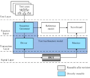
[image:3.612.143.457.372.642.2]The structure of PLD software test platform is shown in Figure 1.
1) Test Layer :Test Layer is the top layer of the PLD software test platform where software testers operate. It incorporates configuration information of test environment and that of Excitation Generator. The connection and communication among modules on lower layers are realized according to configuration of test cases. Different test cases have different test configurations. There is a test case library on Test Layer. With fine scalability, the library allows testers to add test cases required. 2) Scene Layer: Scene Layer is mainly used for the realization of Coverage Information Collector. The collector is composed of excitation generator module and configuration generator module, both of which require flexible controllability. The configuration of both modules under the upper layer environment was tested to generate different excitation and configuration information. Coverage Information Collector requires constrainable random transaction sequences. There shall be scenes to generate corresponding random transaction sequences, depending on test cases. It can be known that the layer is an excitation scene generation library, for which fine scalability is necessary. Thus, test conditions may be added in a convenient way to the Excitation Generator according to test demands.
3) Function Layer: Function Layer lies between Command layer and Coverage Information Collector and is used for abstraction of transactions. The main function of the layer is to test the correctness of the functions in the tested system. Through acquisition of input excitation, the reference model subject to DUT design was used to obtain the expected output. Then, comparison was made between response output and expected output to judge the correctness of design function. Additionally, Function Layer is capable of DUT configuration and it deploys the configuration information generated by Excitation Generator through CPU to DUT. And this layer is also capable of function coverage rate modeling for upper layer input excitation and response output.
4) Transaction Layer: Transaction Layer issues a series of instructions to DUT. It is mainly used for realization of Driver, Monitor and Checker. The layer plays a key role in abstraction at the transaction level. It converts signals on the DUT interface to transaction so as to improve abstraction processing at higher levels. Also, it converts abstraction transaction to specific signal commands and implements them on DUT.
COVERAGE RATE-BASED FUNCTION POINT TEST
The coverage rate-based function point test is supported by test technical framework of reusability test cases. In combination with DO-254, ECSS and FMAC test standards, code coverage and function coverage was regarded as evaluation standards for coverage rate test through engineering software interface development, random and automatic generation of test case excitation, and single-step cycle call. A data report was provided to measure test progress, thus providing an important quantification standard for test cases operating on the PLD software test platform.
TIMING SIMULATION TEST
The simulation conducted on net list files and standard delay format files after locating and wiring is called timing simulation, which involves gate delay and wiring delay information. Timing simulation can not only test functional correctness of the design but also timing correctness of the design. Timing simulation includes the most complete and most accurate delay information and can better reflect the actual operation condition of PLDs. Different locating and wiring schemes would produce different influence on delay due to the difference in internal delay of chips. Thus, after locating and wiring, the platform was used to conduct timing simulation of system and modules, analyze timing relationship and test and calculate system performance.
Prior to timing simulation, the net list files for timing simulation generated by EDA integrated tools (.vho for VHDL and .vo for Verilog) and output files in standard delay format (.sdo), including timing delay information necessary for timing simulation using EDA simulation tools need to be prepared first. Take Quartus II as an example. The path of simulation tools was set as the path of ModelSim and the location for file storage was set well. And netlist files (,vo) and delay files (.sdo) may be obtained through combination again. In ModelSim, timing simulation library files of Quartus II need to be compiled first. Upon completion of compiling, projects were set up and netlist files (.vo) and excitation files (.v) were added. Also, files incorporating delay information (.sdo) were added in simulation and simulation was completed. Identical with the functional simulation, the waveform chart may be observed from the wave window to check if the simulation result is correct. The waveform chart has included timing parameters including device delay and wiring delay, etc. and represents simulation approximating real device operation, with high simulation precision.
STATIC TIMING ANALYSIS
Static timing analysis (STA) is an exhaustive analysis method. The method calculates and checks the duration of setup and retention of each trigging and whether other delay requirements based on paths are satisfied according to the requirements of synchronous circuit design and circuit net list topology. STA represents one of the major test methods in PLD design, with no need of writing test vectors. Test duration is significantly reduced and test coverage may be up to 100%.
Whether PLD device timing analysis satisfies the design requirements depends on the constraints of PLD device timing to a large extent. Timing constraints are one of the most crucial steps in PLD design. After the setting of timing constraints, EDA tools will locate and wire PLDs while satisfying requirements for timing as practically as possible based on the constraints. If timing requirements could not be satisfied through attempts, red alert information will be given to paths that remain to fail to satisfy timing requirements. However, it is not necessary that the more timing constraints are set, the better the effect will be. If plenty of constraints are set, EDA tools would not satisfy all timing constraint requirements in most cases. And the tools regard the final analysis as the result, instead of the analysis most approximating timing requirements. If constraints are set loose, design requirements would not be met in a more optimal way. Thus, timing constraints should be just right.
In timing logic design, the whole circuit may be deemed as a unit of registers and combinational logic elements spaced.
(1) Path 1: Input port to register (2) Path 2: Register to register (3) Path 3: Register to output port (4) Path 4: Input port to output port
Timing analysis aims to ensure all timing paths satisfy the requirements for duration of establishment and retention. Normally, timing constraints need to be added to these paths so as to make the design tool obtain the optimal result.
Timing constraints in PLD device design are generally divided into three categories:
(1) Input pin-to-register constraint (2) Register-to-register constraint (3) Register-to-output pin constraint
output ports and is used to guarantee that the phase relationship between signal output and external device satisfies timing requirements of external receiving device.
All path constraints of synchronous sequential logic design are basically included in the three constraints above. However, as most designs are not only limited to synchronous design but also asynchronous design, it is possible that the setup or retention duration of some registers fails to satisfy timing requirements in the asynchronous clock domains, then causing the failure in obtaining the optimal timing analysis result. One effective solution is to set pseudo path constraints without timing analysis, which can not only save analysis time but also improve timing analysis efficiency.
CONCLUSION
In combination with DO-254, ECSS and FMAC test standards, this paper explicitly identified the definition and technical standards for test framework of reusability test cases, realized hierarchical and abstract structure design of PLD software test platform. The system test hardware and software connected with standard bus interfaces enabled distributed architecture of test hardware and software, parallel synchronous test of multi-channel signals and transition of PLD software test from simple commissioning to integrated test that is systematic, accurate and automatic.
REFERENCES
1. GJB/Z102-1997 Guidelines on Software Reliability [S].