Optimal Control of Automatic Generation with
Automatic Voltage Regulator Using Particle Swarm
Optimization
D. K. Sambariya
∗,
Vivek Nath
Department of Electrical Engineering, Rajasthan Technical University, Kota, 324010, Rajasthan, India
Copyright c⃝2015 by authors, all rights reserved. Authors agree that this article remains permanently
open access under the terms of the Creative Commons Attribution License 4.0 International License
Abstract
A simultaneous study of load frequency control and automatic voltage regulation is considered. The single-area and two-single-area power systems have been considered with a combined model of AGC and AVR for analysis of frequency and voltage deviation. The primary aspect of the design is to keep real power control as to preserve frequency of the system in a prescribed limit. Reactive power control is used to keep the voltage magnitude of synchronous generator at a tolerable limit. The transients produced in dynamic responses are controlled using intelligent and soft-computing technique. The fuzzy logic controller and particle swarm optimization based PID controllers are considered. The steady state error and settling time of the dynamic responses are observed and found to be reduced very effectively. The frequency and terminal voltage results of a single-area power system with proposed PSO-PID controller is compared to the responses of system with controllers presented in literature and found to be more effective. The comparison of fuzzy logic controller with PSO-PID is done by observing the nature of two-area responses. The result obtained by soft computing algorithm and intelligent controller is analyzed on the basis of settling-time, undershoot and ISE Error.Keywords
Automatic Voltage Regulation (AVR), Au-tomatic Load Frequency Cotrol (ALFC), Particle Swarm Optimization (PSO), Fuzzy Logic Control(FLC), Propor-tional Plus Intergal Plus Derivative (PID) Controller, Intergal Square Error1
Introduction
For supplying good and Reliable power to consumer, con-trol of generation is must [1]. If load is change in one area it will badly affect the whole interconnected area, so some control technique is needed to overcome such situation.
By ALFC the deviation in frequency and Tie-line power responses which are generated due to disturbance in power
system are minimized [2]. A change in the Frequency di-rectly depends on rate of generation [3]. where as a change in the excitation is related to voltage magnitude [4]. Com-bined study of AGC and AVR is done together in this pro-posed work [5]. Excitation of the alternator is control for maintaining the reactive power balance. The change in volt-age at alternator terminals are sensed by AVR for brining the voltage at its rated value by adjusting the alternator [6]. At generating station the application of proportional-integral-derivative (PID) controller is in demand. Therefore proper tuning of such controllers is necessary. The optimal tuning of PID gains (Kp,KiandKd) is required for obtaining best
results from tuned controller [7].
The settling time and overshoot of dynamic responses are reduced by using Tuned PID controller. The parame-ter adopted for problem formation is settling time, ISE er-ror and oscillations [8]. In conventional PID controller the parameters are set by hit and trial approach, which is time consuming. To reduce the complexity in tuning PID param-eters, Evolutionary computation techniques are used to solve a wide range of practical problems including calculation of PID gains and optimization it [9].
The response time of integral controller is more and it not able to remove transients from dynamic responses. Therefore for obtaining good and fast responses intelligent controller is needed [10]. The proposed Fuzzy logic control is also used for getting better dynamic reponses. Proposed PSO PID re-sults are compared with FLC [11].
Chandrasekhar and Jayapal [12], presented work on AGC and AVR combined model. PI and PID and Fuzzy controller are implemented for two area systems. Fuzzy controller of-fers better performance then PI and PID. Fuzzy controller corrects the area control error of AGC and Excitation of AVR [13].
Dabur at el [16], analysis the AGC of interconnected ther-mal systems with combination of automatic voltage regula-tion (AVR), design implementaregula-tion and operaregula-tion of fuzzy controller is shown.
Shyama at el [17], proposed controller which is used for tuning LFC and AVR to maintain system responses at nom-inal value. Fuzzy gain scheduled proportional-integral con-troller gives better result than conventional concon-troller [18].
Mukherjyee at el [19], proposed work for AGC and AVR. PSO is used for tuning PID. Nagendra and Krishanayalu [20], presented work for multi - area interconnected power system. The plant responses by considering GRC in examined for ev-ery area. Fuzzy and tuned PID is compared.
In this paper for tuning the PID controller PSO algorithm is used. The tuned PID controller is implemented for mini-mizing deviation in frequency and Tie-line power responses.
2
Automatic voltage regulator
As the coupling between the load frequency control (LFC) and automatic voltage regulation (AVR) system is weak. So they can be studied separately. In this paper the effect of both are considered together. The real power depends on synchro-nizing power coefficientpsand change in the power angle
∆δ. When voltage is consider together then the new expres-sion is formed which is shown in below Eqn. 1.
∆pe=ps∆δ+k2E′ (1)
Wherek2, the change is in electrical power for a small change
in stator emf, the Eqn. 2 shows the small effect of rotor angle upon the generator voltage
∆pe=k5∆δ+k6E′ (2)
Wherek5, represents change in terminal voltage for a small
change in rotor angle at constant stator emf andk6represents
change in terminal voltage for a small change in the stator emf at constant rotor angle. For stable systempsis positive.
The constantsk2, k4, k6 are taken positive andk5 is taken
negative. The process for modelling of an AVR model is car-ried out below.
2.1
Amplifier modelThe gain of the amplifier is denoted bykA, its gain value
is from 10 to 400. Time constant for Amplifier is very small its range lies 0.02 to 0.1 sec. transfer function for amplifier model is
VR(s)
Ve(s)
= KA
I+TAs
(3)
2.2
Exciter modelThe gainkEand time constantTEof exciter is represented
in transfer-function form given as
VF(s)
VR(s)
= KE
1 +TEs
(4)
2.3
Generator modelRange of GainkGis between 0.7 to 1 andTGlies between
1 to 2 seconds.
Vt(s)
VF(s)
= KG
1 +TGs
(5)
2.4
Sensor modelSensor sensed voltage through a potential transformer the
TRtime constant of sensor is assuming a range from 0.01 to
0.06.
VS(s)
Vt(s)
= KR
1 +TRs
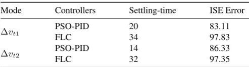
(6) By using the above Eqn. 3 - Eqn. 6, the schematic diagram is made which shown in Fig. 1. From the above block diagram
s
T
K
A A
+
1
T sK
E E
+
1 T s
K
G G
+
1
s T K
R R
+
1
)
(
s
v
ref ve(s))
(
s
v
Rv
F(
s
)
) (s vt
) (s
vS Exciter Generator
Sensor Amplifier
[image:2.595.300.534.295.388.2])
Figure 1.Block diagram of automatic voltage Regulator
in Fig. 1, we can write open loop transfer function which is given as: The relation between generator terminal voltages
Vt(s)to the reference voltageVref(s)is given in Eqn. 8.
3
Problem Formulation
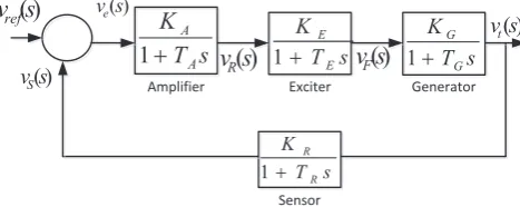
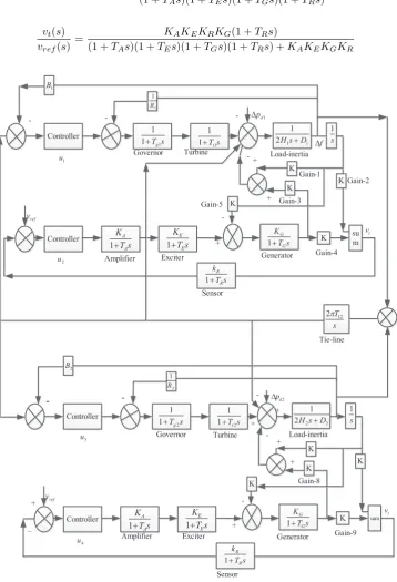
In this paper, study of AGC and AVR is taken together. Two areas interconnected with tie-line are considered for analyzing the behavior of frequency and voltage deviation. The control signal u1, u3 are given to governor in AGC
and u2, u4 are control signal given to amplifier in AVR
model. By implementing FLC and PSO the frequency de-viation (∆f1,∆f2) and voltage deviation (∆v1,∆v2 ) are
controlled. The disturbance of 0.2 p.u is given in both area of automatic generation control connected with tie-line. The step load of 1 p.u is taken in AVR model. When controller is not their steady state error can is there in frequency and voltage response. Block diagram for combine study of AGC and AVR is given in Fig. 2.
3.1
Objective functionLoad frequency of power system to control the deviation of frequency and Tie-line power. The problem is considered for single, two and three-area system as an optimization prob-lem for setting the parameters of PID controller. The param-eters of PID controller (Kp, KiandKd) are considered
with-out specifying the lower and upper bounds. The objective function for optimization is considered as in Eqn. 9.
ISE=
T sim∫
0
|∆f1(t)−∆f2(t)| 2
K G(s)H(s) = KAKEKGKR
(1 +TAs)(1 +TEs)(1 +TGs)(1 +TRs)
(7)
vt(s)
vref(s)
= KAKEKRKG(1 +TRs)
(1 +TAs)(1 +TEs)(1 +TGs)(1 +TRs) +KAKEKGKR
(8)
Controller
Controller K su
m K K s Tg1 1 1
+ 1 Tt1s
1
+ 2 1 1
1
D s
H + s
1 s T K A A +
1 Ts
K
E E
+
1 T s
K G G + 1 s T k R R + 1 Gain-4 Load-inertia Gain-2 K K 1 1 R 1 B f D t v ref v Gain-3 Controller
Controller K sum
K K s 1 s T K A A +
1 Ts
K
E E
+
1 Ts
K G G + 1 s T k R R + 1 Gain-9 Load-inertia K K t v ref v Gain-8 s
Tg2
1 1
+ 1 Tt2s
1
+ 2 2 2
1 D s H + 2 B 2 1 R s T12 2p 1 d p D 2 d p D + 1 u 2 u 3 u 4 u + -+ + _ + - -+ -- - --+ + -+ Governor Turbine Gain-1
Amplifier Exciter Generator
Tie-line
Governor Turbine
Amplifier Exciter Generator
Sensor
[image:3.595.128.487.112.638.2]Sensor Gain-5
Figure 2.Block diagram of combined AGC and AVR
4
Fuzzy Logic Controller
FLC is a very useful method of reasoning when mathemat-ical models are not available and large numbers of input data are present [11]. Fuzzy logic controller is based on fuzzy logic concept [21]. It provides an algorithm by which Expert knowledge based linguistic control starter is converted to au-tomatic control strategy [22]. imprecise but very descriptive language is used by FLC to deal with input data similar to a human operator. Fuzzy logics approach mimics the behav-ior of an person to make decisions must faster [23]. FLC is more useful in solving complex and non-linear control
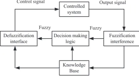
prob-lems for which a conventional controllers takes more time and also less efficient [24]. Fuzzy logic controller has three main components it is fuzzification, knowledge base and de-fuzzification.
Fuzzification: Fuzzification is a process in which crisps quantity is converted into the linguistic variables. Knowledge base: it consists of data base and linguistic control rule base [25, 26].
The data base provides necessary definitions which are used to define linguistic control rules and fuzzy data, ma-nipulation in a FLC [27, 28].
policy of the domain experts by means of set of linguistic control rules [29, 30].
Defuzzification involves turning a set of membership val-ues into a single output value. The block diagram of fuzzy controller used for AGC and AVR is shown in Fig. 3 [31, 32].
Controlled system Controlled
system
Fuzzififf cation interfeff rence Fuzzification interference Decision making
logic Decision making
logic Defuff zzififf cation
interfaff ce Defuzzification
interface
Kn K owledge
Base Knowledge
Base
Control signal Output signal
[image:4.595.295.545.100.257.2]Fuzzy Fuzzy
Figure 3.Block diagram of fuzzy logic controller for load frequency control
5
Particle swarm optimization
The particle swarm optimization (PSO) method is derived by absorbing the behavior of animal like bird flocking, fish scnooling population [33]. For solving an optimization prob-lem PSO use concept of social interaction of animals [34]. This algorithm was developed by James Kennedy in 1995.
Both local search methods and global search methods are combined in PSO system for balancing Exploration and Ex-ploitation. Swarms fly for obtaining a new position. It is done by comparing its own fitness with neighbor fitness. If its near particle have better fitness then with a certain velocity it oc-cupy that position. Swarm keeps its own expression and its neighbor expression in mind at time of searching best fitness value.
Two terms mainly used in algorithm
• Local Best: each particle has proper information about its immediate neighbor by using certain swarm tech-nique.
• Global Best: the particle is attracted towards the best solution found by any particle member in the group of swarms. It means each particle is interconnected with other particles with some topology and can access to-wards the best fitness.
The basic idea on which PSO algorithm work is that each particle is searching for the best solution and each swarm is moving so it has velocity, every particle keeps knowledge about its position where it has best result so far.
The PSO search technique is shown in vector form in Fig. 4. The position of individual particle updated by using Eqn. 10 and velocity is calculated by Eqn. 11.
zmn+1=znm+vnm+1 (10)
vmn+1=vmn +c1r1(pnm−zmn) +c2r2(pgm−zmn) (11)
The variable above is defined as,zn
mis initial searching point,
n m
v
n
m
z
1 +
n m
v
gbest m
v
1
+ n m
z
pbest m
v
bestmp
[image:4.595.43.285.182.317.2]bestm
g
Figure 4.Particle swarm searching technique
zn+1
m modified point searched,vnminitial velocity,vmn+1
mod-ified velocity,vpbest
m velocity based on individual particle
po-sition,vgbest
m velocity based on global best. The acceleration
constant is given asc1, c2; the random value between 0 and
1 is given asr1, r2. The constantsc1 andc2 represent the
weighting of the acceleration terms that allow each particle to reach at its best position.
A balance between global and local explorations is met by Suitable selection of inertia weightω. which reduces the no of iteration value to obtain optimal solution.
ω=ωmax−iter×
ωmax−ωmin
itermax
(12) Theitermaxrepresents maximum number of iteration and
represent current number of iterations.
The design steps of PSO based PID controller for LFC of a power generating system is
• Swarm particle are initiated by a random position
• Fitness of each particle is evaluated
• For every individual particle, Fitness value of particle is compared with its neighbor fitness.if its fitness is better than itspbest value than remain at current position. If
not than neighbor position is occupied by particle with a velocityvn+1
m .
• Now find the global fitness of particle in group of swarm.
• Velocity and position of particle is Update by using equation 10 and 11.
• Repeat the steps 2 to 5 until the desired goal is achieved. It means iteration are stopped when good fitness value is found.
The particle swarm optimization (PSO) is shown in Algo-rithm 1.
6
Result and discussion
Algorithm 1Particle swarm optimization algorithm for tun-ing parameters of proportional-integral-derivative controller
1: procedure OBJECTIVE FUNCTION F(X) AS IN EQN. 10, X = (X1, X2, ..., Xd)T(minimization of objective function;
whereXdis the number of free Coefficients of PID controller
as 6 in numbers for single-area and 12 for two-area power sys-tem)
2: Initialization of the parameters, Size of the swarm i.e. no of birds (n) set to 10; Maximum number of birds steps set to 50; dimension of the problem is set to 6 in case of single-area sys-tem and 12 in case of two-are syssys-tem; the PSO parametersC1 andC2are selected as 1.2 and 0.12 with moment of inertiaωas 0.9, the maximum iteration count is set toItrmaxas 50.
3: The fitness function is defined usingF =Error∗Erroras in Eqn. 9 with parametersX(1) =kp1,X(2) =ki1,X(3) =
kd1,X(4) =kp2,X(5) =ki2,X(6) =kd2.
4: Initializing velocities and position, ”position = 10*(rand(dim, n)-0.5); velocity = 0.3*randn(dim, n)”
5: calculation of initial position of swarms
6: fori= 1 :n, f itness(i) =Fobj(position(:, i))do
7: end for
8: [f itnessgb, g] =min(f itness);
9:
10: fori= 1 :n, positiongb(:, i) =position(:, g)do
11: end for
12: The main-loop operation is set using while loop and started us-ing iter = 0.
13: while(iter < Itrmax)do
14: the iteration count is forwarded as iter = iter + 1;
15: the fitness function is calculated for the set values of bird steps using
16:
17: for i = 1 : n, currentf itness(i) =
Fobj(currentposition(:, i))do;
18: end for
19: the minimum value of the fitness function and position of is selected; the position of swarms is updated using Eqn. 10 and the velocity is updated using Eqn. 11. The weight value is updated using Eqn. 12.
20: end while
21: post process results(fmin, best position) and visualization
22: end procedure
and AVR loop of an area of power system. Therefore, six free coefficiets of two PID controllers in single-area and 12 free coefficients for 4 PID controllers in case of two-area sys-tem are the target of optimization. A load disturbance of 0.2 p.u. is given in two-area system of LFC connected with tie - line. Robustness of interconnected system is seen. A step input of 1 p.u is applied asvref in AVR model. When there is
no controller, there is a steady state error which can be seen in below figures of frequency and voltage response of isolated and multi-area power system.
6.1
Single-area power systemProposed work is carried out for analyzing the dynamic responses (frequency and voltage) using fuzzy logic control (FLC) and particle swarm optimization (PSO) techniques.
The frequency and terminal voltage responses obtained by fuzzy logic controller for a single area system having com-bined model of AGC and AVR is shown in Fig. 5 and Fig. 6. The comparison of proposed controller with recent
pub-Table 1.Comparision of PSO based PID parameters for single-area system with controllers in literature [37, 14, 38]
Controllers Loop Kp Ki Kd
Proposed (PSO-PID) AGC 10.5181 17.7225 3.5581 AVR 3.3892 1.0137 3.5808 Thakur [37] AGC 0.8300 0.5400 0.1400 AVR 4.2155 4.5999 0.5789 Anbarasi [14] AGC 3.1850 4.6700 0.6556 AVR 0.7886 0.6086 0.3357 Sadaat [38] AGC 1.0000 0.2800 0.2500 AVR 1.0000 0.2800 0.2500
lished paper PID is carried out. The optimal values of PSO based PID for single-area and two-area systems are included in Table 1 and Table 2, respectively. By analysis, it is found that proposed controller results are better than classical con-troller. Both classical and intelligent controller reduces the steady state error to zero but the settling time and ISE error of proposed controller are very small as compared to conven-tional PID controllers. The integral of squared error (ISE) is well defined in [35, 23, 32, 36]. Comparison of Intelligent controller with PID controller on the basis of settling-time, under-shoot and ISE error is in Table 3 and Table 4.
Some of the observations are enlisted as following:
• Frequency response of single-area system with pro-posed fuzzy logic controller settles at 16 seconds while it settles at 18, 22 and 30 seconds with controllers pre-sented in Thakur [37], Anbarasi [14] and Sadaat [38], respectively as in Table 3..
• The value of ISE error of frequency response is 0.00111 while that of with controllers in in Thakur [37], An-barasi [14] and Sadaat [38] is 0.00168, 0.04120 and 0.00685, respectively.
• The terminal voltage response with proposed fuzzy con-troller settles at 6 seconds while that of with Thakur [37], Anbarasi [14] and Sadaat [38], settles in 14, 10 and 16 seconds, respectively as in Table 4.
• The ISE error of terminal voltage response with pro-posed fuzzy controller, Thakur [37], Anbarasi [14] and Sadaat [38] is 48.52, 50.92, 49.74 and 48.65, respec-tively.
[image:5.595.311.559.122.231.2]• The settling time with proposed PSO-PID for frequency response is 8 seconds (as in Table 5) and the settling time for voltage response is 10 seconds (as in Table 6). The response is appreciable improved as com-pared to the responses with controllers in literature [37, 14, 38]. Similarly, the ISE error with proposed PSO-PID is highly reduced as compared to the con-trollers in [37, 14, 38].
Table 2.The parameters of the PID controller using PSO algorithm for two-area system with controllers in literature [37, 14, 38]
Loop Area Kp Ki Kd
[image:6.595.43.291.121.188.2]AGC Area-1 6.7292 9.0540 6.3230 Area-2 5.2940 4.5847 3.8312 AVR Area-1 4.1512 16.3485 3.0177 Area-2 2.1296 4.7747 1.2329
Table 3.Frequency response of single-area power system with fuzzy logic controller and controllers in literature [37, 14, 38]
Controllers Settling-time Under-shoot ISE Error Proposed (Fuzzy) 16 -0.0250 0.00111 Thakur [37] 18 -0.0400 0.00168 Anbarasi [14] 22 -0.0410 0.04120 Sadaat [38] 30 -0.0181 0.00685
0 5 10 15 20 25 30 35 40 −0.04
−0.03 −0.02 −0.01 0 0.01 0.02
Time (s)
Frequency deviation
Frequency response for single−area system
Proposed (Fuzzy) PID (Thakur, 2014) PID (Anbarsi, 2014) PID (Sadaat, 2009) (No−Controller)
Figure 5. Frequency response for a single area power system obtained by Fuzzy logic controller [37, 14, 38]
and Fig. 8. Frequency and voltage responses obtained by PSO tuned PID and compared with conventional controller on basis of settling-time, undershoot and integral square er-ror (ISE) is given in Table 5 and Table 6.
6.2
Two-area power systemThe fuzzy logic controller and PSO tuned PID controller is implemented for a two area power system having combined model of ALFC and AVR.
The frequency responses obtained by Fuzzy and PSO tuned PID controller is shown in Fig. 9 and Fig. 10. The Tuned PID results are supreme as compared to fuzzy logic controller. Tie-line power response is given in Fig. 13.
Table 4.Terminal voltage response of single-area power system with fuzzy logic controller and controllers in literature [37, 14, 38]
Controllers Settling-time Under-shoot ISE Error Proposed (Fuzzy) 6 - 48.52 Thakur [37] 14 0.4 50.92 Anbarasi [14] 10 - 49.74 Sadaat [38] 16 0.93 48.65
0 5 10 15 20
0 0.2 0.4 0.6 0.8 1 1.2 1.4 1.6 1.8 2
Time (s)
Voltage deviation
Voltage response for single−area system
[image:6.595.45.279.226.490.2]Proposed (Fuzzy) PID (Thakur, 2014) PID (Anbarsi, 2014) PID (Sadaat, 2009) (No−Controller)
[image:6.595.298.545.351.418.2]Figure 6.Terminal voltage response for a single area power system obtained by Fuzzy logic controller [37, 14, 38]
Table 5. Frequency response of single-area power system with proposed PID-PSO controller and controllers in literature [37, 14, 38]
Controllers Settling-time Under-shoot ISE Error Proposed (PSO-PID) 8 -8.1×10⁻³
0.0001 Thakur [37] 18 - 0.04 0.00168 Anbarasi [14] 22 -8.85×10⁻³ 0.0412 Sadaat [38] 30 - 0.0181 0.00685
0 5 10 15 20 25
−0.05 −0.04 −0.03 −0.02 −0.01 0 0.01 0.02
Time (s)
Frequency deviation
Frequency response for single−area system
Proposed (PSO−Controller) PID (Thakur, 2014) PID (Anbarsi, 2014) PID (Sadaat, 2009) No−Controller
Figure 7. Frequency response for a single area power system obtained by PSO tuned PID controller [13, 22, 23]
[image:6.595.300.531.361.619.2]The terminal voltage responses are shown in Fig. 11 and Fig. 12 for AVR. It is absorbed that settling - time of terminal voltage simulated by PSO is quite fast as compared to FLC
Table 6. Terminal voltage response of single-area power system with pro-posed PID-PSO controller and controllers in literature [37, 14, 38]
[image:6.595.51.541.756.821.2]0 5 10 15 20 25 0
0.2 0.4 0.6 0.8 1 1.2 1.4 1.6 1.8
Time (s)
Voltage deviation
Voltage response of single−area system
[image:7.595.71.288.96.276.2]Proposed (PSO−Controller) PID (Thakur, 2014) PID (Anbarsi, 2014) PID (Sadaat, 2009) Without Controller
Figure 8.Terminal voltage response for a single area power system obtained by PSO tuned PID controller [13, 22, 23]
voltage response. Both controllers are succeeding in reduc-ing steady state error to zero. Comparative analysis of both proposed controller on basis of settling time, under-shoot and ISE error for frequency and Tie-line power is given in Table 7. For terminal voltage comparison is given in Table 8. Data used for ALFC for isolated system is similar to area-1 data given in Appendix - A and for AVR model data is given in Appendix - B.
0 10 20 30 40 50
−0.05 −0.04 −0.03 −0.02 −0.01 0 0.01
Time (s)
Frequency deviation
Frequency response for area−1 of 2−area system
[image:7.595.315.537.98.277.2]Proposed (Fuzzy−Controller) Proposed (PSO−Controller) No−Controller
Figure 9.Frequency response for area-1 of two-area power system
Some important observations from the responses of the system with fuzzy logic controller and with PSO-PID con-troller are as following:
• The settling time observed for frequency response with proposed PSO-PID controller is 13 seconds for area-1 and 18 seconds for area-2; which is much lesser as com-pared to fuzzy response as 27 seconds and 25 seconds, respectively (Table 7).
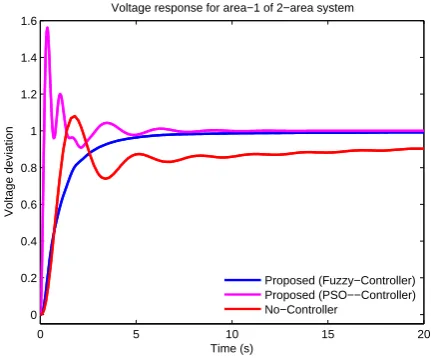
• The terminal voltage response for area-1 and area-2 with PSO-PID controller is 20 and 14 seconds, while that of with fuzzy controller is 34 and 32 seconds, respec-tively. Therefore, it is easy to say that the response with
0 10 20 30 40 50
−0.03 −0.025 −0.02 −0.015 −0.01 −0.005 0
Time (s)
Frequency deviation
Frequency response for area−1 of 2−area system
[image:7.595.323.539.329.508.2]Proposed (Fuzzy−Controller) Proposed (PSO−Controller) No−Controller
Figure 10.Frequency response for area-2 of two-area power system
0 5 10 15 20
0 0.2 0.4 0.6 0.8 1 1.2 1.4 1.6
Time (s)
Voltage deviation
Voltage response for area−1 of 2−area system
Proposed (Fuzzy−Controller) Proposed (PSO−−Controller) No−Controller
Figure 11.Terminal voltage response for area-1 of two-area power system
0 5 10 15 20
0 0.2 0.4 0.6 0.8 1 1.2
Time (s)
Voltage deviation
Voltage response for area−2 of 2−area system
Proposed (Fuzzy−Controller) Proposed (PSO−−Controller) No−Controller
Figure 12.Terminal voltage response for area-2 of two-area power system
[image:7.595.64.286.442.621.2] [image:7.595.321.539.560.741.2]0 10 20 30 40 50 −0.04
−0.035 −0.03 −0.025 −0.02 −0.015 −0.01 −0.005 0 0.005 0.01
Time (s)
Power deviation
Tie−line power response of two−area system
[image:8.595.46.275.94.278.2]Proposed (Fuzzy−Controller) Proposed (PSO−Controller) No−Controller
[image:8.595.45.289.332.418.2]Figure 13.Tie-Line power response for two-area power system
Table 7.Frequency response analysis for interconnected power system
Mode Controllers Settling-time Under-shoot ISE Error
∆f1
PSO-PID 13 - 0.0108 0.0012 FLC 27 - 0.038 0.0021
∆f2
PSO-PID 18 - 0.0058 0.0018 FLC 25 - 0.03 0.0013
∆Tp
PSO-PID 32 - 0.003 0.00214 FLC 45 - 0.03 0.0014
7
Conclusion
In this paper, single-area and two-area power system mod-els are considered with AGC and AVR loops. The two dif-ferent controllers, (i) fuzzy logic controller and (ii) particle swarm optimization based PID controllers; are designed for both of the above power systems.
It have been presented that the response with fuzzy logic con-troller is better in terms of reduced settling time and mini-mum value of ISE error as compared to the response with controllers in [37, 14, 38]. However, the response of system with proposed PSO-PID controller is better to the fuzzy con-troller and concon-trollers in [37, 14, 38].
In case of two-area power system, the PSO-PID based re-sponse is proven to be better in terms of reduced settling time and minimum ISE error as compared to fuzzy controller.
Appendix - A
The data for inter-connected system:
• Governor speed regulation:R1= 0.051,R2= 0.065
Table 8.Terminal voltage response analysis for interconnected power sys-tem
Mode Controllers Settling-time ISE Error
∆vt1
PSO-PID 20 83.11
FLC 34 97.83
∆vt2
PSO-PID 14 86.33
FLC 32 97.35
• Frequency bias factors:D1= 0.62,D2= 0.91
• Inertia constant:H1= 5,H2= 4
• Governor time constant:Tg1= 0.2,Tg2= 0.3
• Turbine time constant:Tt1= 0.5,Tt2= 0.6
• Load disturbance:∆pd1= 0.2,∆pd2= 0.2
Appendix - B
The data used for AVR is given as:
Amplifier gainKA = 9, its time constantTA = 0.1,
Ex-citer gain KE = 1, Time-constantTE = 0.1,
Generator-gainKG= 1.0and its time constantTG = 1.0, Sensor gain
KR= 1and its time constantTR= 0.05.
REFERENCES
[1] S. Satyanarayana, R. Sharma, Mukta, and A. Sappa, “Auto-matic generation control in power plant using pid, pss and fuzzy-pid controller,” in International Conference on Smart Elec-tric Grid (ISEG,’14’), Sept 2014, pp. 1–8. [Online]. Available: http://dx.doi.org/10.1109/ISEG.2014.7005618
[2] C. Srinivasa Rao, “Adaptive neuro fuzzy based load frequency con-trol of multi area system under open market scenario,” inInternational Conference on Advances in Engineering, Science and Management (ICAESM, ’12’), March 2012, pp. 5–10.
[3] R. Umrao and D. Chaturvedi, “Load frequency control us-ing polar fuzzy controller,” in IEEE Region 10 Conference TENCON-2010, Nov 2010, pp. 557–562. [Online]. Available: http:/dx.doi.org/10.1109/TENCON.2010.5686740
[4] V. Nath and D. K. Sambariya, “Analysis of agc and avr for single area and double area power system using fuzzy logic control,” International Journal of Advanced Research in Electrical, Electronics and Instrumentation Engineering, vol. 4, no. 7, pp. 6501–6511, 2015. [Online]. Available: http://dx.doi.org/10.15662/ijareeie.2015.0407075
[5] A. M. Hamza, M. S. Saad, H. M. Rashad, and A. Bahgat, “Design of lfc and avr for single area power system with pid controller tuning by bfo and ziegler methods,”International Journal of Computer Science and Telecommunications, vol. 4, no. 5, pp. 12–17, 2013.
[6] N. Yegireddy and S. Panda, “Design and performance analysis of pid controller for an avr system using multi-objective non-dominated shorting genetic algorithm-ii,” inInternational Conference on Smart Electric Grid (ISEG, ’14’), Sept 2014, pp. 1–7. [Online]. Available: http://dx.doi.org/10.1109/ISEG.2014.7005600
[7] S. J. Bassi, M. K. Mishra, and E. E. Omizegba, “Automatic tuning of proportional integral derivative (PID) controller using particle swarm optimization (PSO) algorithm,” International Journal of Artificial Intelligence&Applications, vol. 2, no. 4, pp. 25–34, 2011. [Online]. Available: http://dx.doi.org/10.5121/ijaia.2011.2403
[8] T. Pati, J. Nayak, B. Sahu, and S. Kar, “Automatic generation control of multi-area thermal power system using tlbo algorithm optimized fuzzy-pid controller,” inInternational Conference on Circuit, Power and Computing Technologies (ICCPCT, ’15’), March 2015, pp. 1–6. [Online]. Available: http://dx.doi.org/10.1109/ICCPCT.2015.7159263
[9] S. Gautam and N. Goyal, “Improved particle swarm optimization based load frequency control in a single area power system,” inAnnual IEEE India Conference (INDICON’10), Dec 2010, pp. 1–4. [Online]. Available: http:/dx.doi.org/10.1109/INDCON.2010.5712725
[image:8.595.42.289.754.821.2][11] C. Chang and W. Fu, “Area load frequency control using fuzzy gain scheduling of {PI} controllers,” Electric Power Sys-tems Research, vol. 42, no. 2, pp. 145 – 152, 1997. [Online]. Available: http://www.sciencedirect.com/science/article/pii/S0378779696011996
[12] M. J. Chandrashekar and R. Jayapal, “Performance analysis of fl, pi and pid controller for agc and avr of a two-area power system,” Inter-national Journal of Scientific and Research Publications, vol. 5, no. 1, pp. 1–7, January 2015.
[13] V. Nath and D. K. Sambariya, “Application of NARMA L2 controller for load frequency control of multi-area power system,” inIEEE Pro-ceeding of10thInternational Conference on Intelligent Systems and Control (ISCO 2016), vol. 2, 2016, pp. 352–358.
[14] S. Anbarasi and S. Muralidharan, “Transient stability improvement of lfc and avr using bacteria foraging optimization algorithm,” Interna-tional Journal of Innovative Research in Science, Engineering and Technology, vol. 3, no. 3, pp. 124–129, March 2014.
[15] V. Nath and D. K. Sambariya, “Design and performance analysis of adaptive neuro fuzzy controller for load frequency control of multiarea power system,” inIEEE Proceeding of10thInternational Conference on Intelligent Systems and Control (ISCO 2016), vol. 2, 2016, pp. 359– 365.
[16] P. Dabur, N. K. Yadav, and V. K. Tayal, “Matlab design and simulation of agc and avr for multi area power system and demand side manage-ment,”International Journal of Computer and Electrical Engineering, vol. 3, no. 2, pp. 259–264, April 2011.
[17] T. R. Shyama, R. S. Kumar, and V. Shanmugasundaram, “Design of fgspi controller based combined lfc and avr of two area interconnected power generating system,”International Journal of Engineering and Advanced Technology, vol. 1, no. 4, pp. 135–139, April 2012.
[18] D. K. Sambariya and V. Nath, “Load frequency control using fuzzy logic based controller for multi-area power system,”British Journal of Mathematics & Computer Science, vol. 13, no. 5, pp. 1–19, 2016. [Online]. Available: http://dx.doi.org/10.9734/BJMCS/2016/22899
[19] V. Mukherjee and S. Ghoshal, “Intelligent particle swarm optimized fuzzy PID controller for AVR system,” Electric Power Systems Research, vol. 77, no. 12, pp. 1689 – 1698, 2007. [Online]. Available: http://www.sciencedirect.com/science/article/pii/S0378779606002896
[20] M. Nagendra and M. S. Krishnarayalu, “Agc and avr of multi area pow-ersystems with and without grc nonlinearity,”International Journal of Advanced Research in Electrical, Electronics and Instrumentation En-gineering, vol. 2, no. 6, pp. 2117 – 2126, June 2013.
[21] D. K. Sambariya and R. Gupta, “Fuzzy logic based power systems sta-bilizer for kota thermal power station,” inInternational Conference on Computers, Controls and Communication (INCON-CCC-2004), 2004, pp. 307–316.
[22] K. M. Dash, S. Sahoo, and S. Mishra, “A detailed analysis of optimized load frequency controller for static and dynamic load variation in an ac microgrid,” in Condition Assessment Techniques in Electrical Systems (CATCON), 2013 IEEE 1st International Conference on, Dec 2013, pp. 17–22. [Online]. Available: http://dx.doi.org/10.1109/CATCON.2013.6737467
[23] D. K. Sambariya, “Power system stabilizer design using compressed rule base of fuzzy logic controller,” Journal of Electrical and Electronic Engineering, vol. 3, no. 3, pp. 52–64, 2015. [Online]. Available: http://dx.doi.org/10.11648/j.jeee.20150303.16
[24] D. K. Sambariya and R. Gupta, “Fuzzy logic based power system sta-bilizer for multi-machine system,” inThirteenth, National Power Sys-tems Conference (NPSC-2004), 2004, pp. 257–261.
[25] D. K. Sambariya and R. Gupta, “Fuzzy logic based robust multi-machine power system stabilizer,” in International Conference on Computer Applications in Electrical Engineering Recent Advances, (CERA-2005), 2005, pp. 436–442.
[26] D. K. Sambariya, R. Gupta, and A. Sharma, “Fuzzy applications to single machine power system stabilizers,”Journal of Theoretical and Applied Information Technology, vol. 5, no. 3, pp. 317–324, 2009. [Online]. Available: http://www.jatit.org
[27] D. K. Sambariya and R. Gupta, “Fuzzy applications in a multi-machine power system stabilizer,”Journal of Electrical Engineering and Technology, vol. 5, no. 3, pp. 503–510, 2010. [Online]. Available: http://www.jeet.or.kr
[28] D. K. Sambariya, “Power system stabilizer with fuzzy logic for multi-machine system,” inNational Conference on Power and Energy Sys-tems, (NCPES-2011), 2011, pp. 200–204.
[29] D. K. Sambariya and R. Prasad, “Fuzzy pss for single machine infi-nite bus power system,” inInternational Conference on Power Elec-tronics and Energy Systems (PEES-2012), ISBN : 978-81-920249-8-1; Department of Electrical Engineering, Chitkara University, 2012, pp. 23–27.
[30] D. K. Sambariya and R. Prasad, “Robust power system stabilizer de-sign for single machine infinite bus system with different membership functions for fuzzy logic controller,” in7th International Conference on Intelligent Systems and Control (ISCO, ’13’), Jan 2013, pp. 13–19. [Online]. Available: http://dx.doi.org/10.1109/ISCO.2013.6481115
[31] D. K. Sambariya and R. Prasad, “Design of harmony search algorithm based tuned fuzzy logic power system stabilizer,”International Review of Electrical Engineering (IREE), vol. 8, no. 5, pp. 1594–1607, 2013. [Online]. Available: http://dx.doi.org/10.15866/iree.v8i5.2117
[32] D. K. Sambariya and R. Prasad, “Optimal tuning of fuzzy logic power system stabilizer using harmony search algorithm,” International Journal of Fuzzy Systems, vol. 17, no. 3, pp. 457–470, 2015. [Online]. Available: http://dx.doi.org/10.1007/s40815-015-0041-4
[33] R. N. Rao and P. R. K. Reddy, “Pso based tuning of pid controller for a load frequency control in two area power system,”International Jour-nal of Engineering Research and Applications (IJERA), vol. 1, no. 4, pp. 1499–1505, Nov-Dec 2011.
[34] S. Pain and P. Acharjee, “Multiobjective optimization of load fre-quency control using pso,”International Journal of Emerging Tech-nology and Advanced Engineering, vol. 4, no. 7, pp. 16–22, 2014.
[35] D. K. Sambariya and R. Prasad, “Robust tuning of power system stabilizer for small signal stability enhancement using metaheuristic bat algorithm,”International Journal of Electrical Power & Energy Systems, vol. 61, no. 0, pp. 229–238, 2014. [Online]. Available: http://dx.doi.org/10.1016/j.ijepes.2014.03.050
[36] D. K. Sambariya and R. Prasad, “Design of robust PID power system stabilizer for multimachine power system using HS algorithm,” Ameri-can Journal of Electrical and Electronic Engineering, vol. 3, no. 3, pp. 75–82, 2015. [Online]. Available: http://dx.doi.org/10.12691/ajeee-3-3-3
[37] G. S. Thakur and A. Patra, “Power plant load frequency control in single area with traditional ziegler - nichols - pid tuning controller,” Advanced Research in Electrical and Electronic Engineering, vol. 2, no. 12, pp. 49–53, Dec 2014.
![Table 1. Comparision of PSO based PID parameters for single-area systemwith controllers in literature [37, 14, 38]](https://thumb-us.123doks.com/thumbv2/123dok_us/8752372.892186/5.595.311.559.122.231/table-comparision-based-parameters-single-systemwith-controllers-literature.webp)
![Table 5. Frequency response of single-area power system with proposedPID-PSO controller and controllers in literature [37, 14, 38]](https://thumb-us.123doks.com/thumbv2/123dok_us/8752372.892186/6.595.300.531.361.619/table-frequency-response-single-proposedpid-controller-controllers-literature.webp)