IMPLEMENTATION OF MULTI CARRIER-CODE DIVISION
MULTIPLE ACCESS-FREQUENCY DIVISION MULTIPLE ACCESS
WITH BEYOND 4G SPECIFICATIONS
MAYADA FARIS GHANIM ALOMARY
A thesis submitted in
fulfillment of the requirement for the award of the
Doctor of Philosophy
Faculty of Electrical and Electronic Engineering
Universiti Tun Hussein Onn Malaysia
VII
ABSTRACT
VIII
ABSTRAK
IX
TABLE OF CONTENTS
TITLE I
DECLARATION IV
ACKNOWLEDGEMENT VI
ABSTRACT VII
TABLE OF CONTENTS IX
LIST OF FIGURES XVI
LIST OF TABLES XXI
CONTRIBUTIONS AND PUBLISHED WORKS XXIII
LIST OF ABBREVIATIONS XXVII
CHAPTER 1 INTRODUCTION 1
1.1 Research Background 1
1.2 Problem statement 2
1.3 Objectives of the research 3
1.4 Research Methodology 4
1.5 Scope of the research 6
X
1.7 Thesis Outlines 8
CHAPTER 2 MULTIPLE ACCESS SCHEMES 10
2.1 Introduction 10
2.2 Frequency Division Multiple Access (FDMA) 11 2.3 Time Division Multiple Access (TDMA) 14 2.4 Orthogonal Frequency Division Multiple Access
(OFDMA)
16
2.5 Code Division Multiple Access (CDMA) 17 2.5.1 Direct Sequence Code Division Multiple Access
(DS-CDMA)
19
2.5.2 Frequency Hopping Code Division Multiple Access (FH-CDMA)
20
2.5.3 Time Hopping Code Division Multiple Access (TH-CDMA)
23
2.5.4 Hybrid Code Division Multiple Access 24 2.5.4.1 Multi Carrier-Code Division Multiple Access
(MC-CDMA)
25
XI
Access (MC-DS-CDMA)
2.5.4.3 Time Division-Synchronous Code Division Multiple Access (TD-SCDMA)
27
2.6 Summary 28
CHAPTER 3 MULTI CARRIER-CODE DIVISION MULTIPLE
ACCESS
29
3.1 Introduction 29
3.2 MC-CDMA System Structure 30
3.2.1 MC-CDMA Signal Generation 30
3.2.2 MC-CDMA Signal Analysis 31
3.2.3 MC-CDMA Downlink Signal 33
3.2.4 MC-CDMA Uplink Signal 36
3.3 Spreading Codes 38
3.3.1 Orthogonal Walsh Codes 39
3.3.2 Pseudo Noise Codes 43
XII
3.8 PAPR reduction techniques for MC-CDMA System 51 3.8.1 Amplitude Clipping and Filtering 51
3.8.2 Coding 52
3.8.3 Selective Mapping 53
3.8.4 The Adaptive pre-distortion Technique 54
3.8.5 DFT Spreading 54
3.9 PAPR Reduction Techniques Comparison 56
3.10 Summary 59
CHAPTER 4 SINGLE CARRIER-FREQUENCY DIVISION MULTIPLE
ACCESS
60
4.1 Introduction 60
4.2 SC-FDMA Transmission Structure 61 4.2.1 Time-Domain Signal Generation 62 4.2.2 Frequency-Domain Signal Generation (DFT-S-OFDM) 65 4.3 SC-FDMA Time and Frequency Structure 70
4.4 Advantages of SC-FDMA 75
4.5 Drawbacks of SC-FDMA 76
4.6 Peak-to-Average Power Ratio Characteristics of SC-FDMA system
77
XIII
CHAPTER 5 DESIGN OF MC-CDMA, SC-FDMA AND MC-CDMA-FDMA
SYSTEMS
79
5.1 Introduction 79
5.2 Design of MC-CDMA System 80
5.3 Design of SC-FDMA System 84
5.4 Design of MC-CDMA-FDMA System 87 5.5 Optimization of FFT size for MC-CDMA, SC-FDMA
and MC-CDMA-FDMA
99
5.6 Summary 101
CHAPTER 6 PERFORMANCE ANALYSIS OF MC-CDMA, SC-FDMA
AND MC-CDMA-FDMA
102
6.1 Introduction 102
6.2 Performance of MC-CDMA System 103 6.2.1 Performance of MC-CDMA System with Walsh
Hadamard Code
103
6.2.1.1 Performance of MC-CDMA System over AWGN Channel
105
6.2.1.2 Performance of MC-CDMA System over Rayleigh
Fading and AWGN Channel
107
6.2.2 Performance of MC-CDMA System with Pseudo
Random Code
110
6.2.2.1 Performance of MC-CDMA System over AWGN
Channel
XIV
6.2.2.2 Performance of MC-CDMA System over Rayleigh Fading and AWGN Channel
114
6.2.3 Comparison of Simulated MC-CDMA system with Previous Work done elsewhere
117
6.2.4 PAPR of MC-CDMA System over Rayleigh and AWGN Channel
118
6.2.5 MC-CDMA System with N-point FFT size 120 6.2.5.1 MC-CDMA System with QAM Modulation Technique 120 6.2.5.2 MC-CDMA System with PSK Modulation Technique 122 6.2.6 PAPR of MC-CDMA with N-point FFT Size 131 6.3 Performance of SC-FDMA System 132 6.3.1 Performance of SC-FDMA system with Various
Modulation Techniques
135
6.3.2 Peak Power Characteristics of Single Carrier FDMA Signal
136
6.3.3 SC-FDMA System with N-point FFT size 137 6.3.3.1 SC-FDMA System with QAM Modulation Technique 137 6.3.3.2 SC-FCDMA System with PSK Modulation Technique 140 6.4 Performance of MC-CDMA-FDMA System 149 6.4.1 Performance of MC-CDMA-FDMA System with
Various Modulation Techniques
150
XV
6.4.3.1 MC-CDMA-FDMA System with QAM Modulation Technique
154
6.4.3.2 MC-CDMA-FDMA System with PSK Modulation Technique
156
6.5 Summary 165
CHAPTER 7 CONCLUSIONS AND FUTURE WORKS 168
7.1 Conclusions 168
7.2 Recommendations and Future Works 171
REFERENCES 172
XVI
LIST OF FIGURES
2.1 An illustration of different multiple access scheme concepts 11 2.2 Principle of frequency division multiple access 12 2.3 Principle behind time division multiple access 14 2.4 Classification of CDMA Techniques 18 2.5 Carrier frequency hopping from one frequency to another 21
2.6 Basic FH transmitter 22
2.7 Block diagram of TH-CDMA transmitter and receiver 24 2.8 MC-DS-CDMA transmitter for M carriers 26 3.1 MC-CDMA signal generation for one user 31 3.2 Multi-carrier spread spectrum signal generation 33
3.3 MC-CDMA downlink transmitter 34
3.4 OFDM block 35
3.5 MC-CDMA Receiver 37
3.6 Inverse OFDM block 37
XVII
3.13 Block diagram of selective mapping (SLM) technique for PAPR reduction
53
3.14 Subcarrier mapping for uplink in OFDMA systems: DFDMA and LFDMA
55
4.1 SC-FDMA time-domain transmit processing 62 4.2 Distributed transmission with equal-spacing between occupied
subcarriers
63
4.3 SC-FDMA frequency-domain transmit processing (DFT-S-OFDM) showing localized and distributed subcarrier mappings
65
4.4 Subcarrier mapping modes; distributed and localized 67 4.5 Different subcarrier mapping schemes for M = 4, Q = 3, and N
= 12
68
4.6 Multiple access with resource sharing in the frequency domain with SC-FDMA and frequency domain signal generation
69
4.7 Uplink resource grid 73
4.8 Physical mapping of a block in RF frequency domain (fc: carrier center frequency)
75
5.1 MC-CDMA Diagram of Transmitter 81
5.2 MC-CDMA Diagram of Receiver 83
5.3 SC-FDMA Diagram of Transmitter 85
5.4 SC-FDMA Diagram of Receiver 86
5.5 MC-CDMA-FDMA Diagram of Transmitter 92 5.6 Spreading and De-spreading operations 93 5.7 MC-CDMA-FDMA Diagram of Receiver 95 5.8 BER values for MC-CDMA-FDMA, MC-CDMA and
SC-FDMA at SNR=8dB
97
XVIII
6.1 MC-CDMA system (4 Users) broadcasting on AWGN channel 105 6.2 MC-CDMA system (16 Users) broadcasting on AWGN
channel
106
6.3 MC-CDMA system (32 Users) broadcasting on AWGN channel
106
6.4 MC-CDMA system (64 Users) broadcasting on AWGN channel
107
6.5 MC-CDMA system (4 Users) over Rayleigh fading and AWGN channel
108
6.6 MC-CDMA system (16 Users) broadcasting on Rayleigh fading and AWGN channel
108
6.7 MC-CDMA system (32 Users) broadcasting on Rayleigh fading and AWGN channel
109
6.8 MC-CDMA system (64 Users) broadcasting on Rayleigh fading and AWGN channel
110
6.9 MC-CDMA system (4Users) broadcasting on AWGN channel 111 6.10 MC-CDMA system (16Users) broadcasting on AWGN channel 112 6.11 MC-CDMA system (32Users) broadcasting on AWGN channel 113 6.12 MC-CDMA system (64Users) broadcasting on AWGN channel 113 6.13 MC-CDMA system (4Users) broadcasting on Rayleigh fading
and AWGN channel
114
6.14 MC-CDMA system (16Users) broadcasting on Rayleigh fading and AWGN channel
115
6.15 MC-CDMA system (32Users) broadcasting on Rayleigh fading and AWGN channel
116
6.16 MC-CDMA system (64Users) broadcasting on Rayleigh fading and AWGN channel
XIX
6.17 PAPR of MC-CDMA system 119
6.18 BER for MC-CDMA system using QAM modulation technique 120 6.19 BER for MC-CDMA system using BPSK modulation technique 122 6.20 BER for MC-CDMA system using QPSK modulation
technique
124
6.21 BER for MC-CDMA system using 8PSK modulation technique 126 6.22 BER for MC-CDMA system using 16PSK modulation
technique
128
6.23 BER for MC-CDMA system using 32PSK modulation technique
129
6.24 PAPR for MC-CDMA system with various FFT size 131 6.25 Flow chart of SC-FDMA block diagram 133 6.26 BER for SC-FDMA system using different modulation
techniques
135
6.27 PAPR for SC-FDMA system 136
6.28 BER for SC-FDMA system using QAM modulation technique 138 6.29 BER for SC-FDMA system using BPSK modulation technique 140 6.30 BER for SC-FDMA system using QPSK modulation technique 142 6.31 BER for SC-FDMA system using 8PSK modulation technique 144 6.32 BER for SC-FDMA system using 16PSK modulation technique 146 6.33 BER for SC-FDMA system using 32PSK modulation technique 148 6.34 BER for MC-CDMA system using different modulation
techniques
150
6.35 BER for MC-CDMA-FDMA system using different modulation techniques
151
XX
6.37 BER for MC-CDMA-FDMA system using QAM modulation technique.
154
6.38 BER for MC-CDMA-FDMA system using BPSK modulation technique
156
6.39 BER for MC-CDMA-FDMA system using QPSK modulation technique
158
6.40 BER for MC-CDMA-FDMA system using 8PSK modulation technique
160
6.41 BER for MC-CDMA-FDMA system using 16PSK modulation technique
162
6.42 BER for MC-CDMA-FDMA system using 32PSK modulation technique
XXI
LIST OF TABLES
3.1 Index for Walsh code of length 8 41 3.2 Advantages and disadvantages of PAPR reduction techniques 58 4.1 Resource block characteristics 71 4.2 Summary of symbols for uplink physical layer description 71 4.3 Normal cyclic prefix and extended cyclic prefix 74
5.1 Simulation Parameters 96
6.1 Comparison of MC-CDMA system with other researchers’ systems
117
6.2 Relationship between FFT size and BER in case of QAM modulation technique
121
6.3 Relationship between FFT size and BER in case of BPSK modulation technique
123
6.4 Relationship between FFT size and BER in case of QPSK modulation technique
125
6.5 Relationship between FFT size and BER in case of 8PSK modulation technique
127
6.6 Relationship between FFT size and BER in case of 16PSK modulation technique
128
6.7 Relationship between FFT size and BER in case of 32PSK modulation technique
XXII
6.8 Optimum FFT size for MC-CDMA system 132 6.9 Relationship between FFT size and BER in case of QAM
modulation technique
139
6.10 Relationship between FFT size and BER in case of BPSK modulation technique
141
6.11 Relationship between FFT size and BER in case of QPSK modulation technique
143
6.12 Relationship between FFT size and BER in case of 8PSK modulation technique.
145
6.13 Relationship between FFT size and BER in case of 16PSK modulation technique
147
6.14 Relationship between FFT size and BER in case of 32PSK modulation technique
149
6.15 Relationship between FFT size and BER in case of QAM modulation technique
155
6.16 Relationship between FFT size and BER in case of BPSK modulation technique
157
6.17 Relationship between FFT size and BER in case of QPSK modulation technique
159
6.18 Relationship between FFT size and BER in case of 8PSK modulation technique
161
6.19 Relationship between FFT size and BER in case of 16PSK modulation technique
163
6.20 Relationship between FFT size and BER in case of 32PSK modulation technique
165
6.21 Comparison of MC-CDMA, SC-FDMA, and MC-CDMA-FDMA
XXVII
LIST OF ABBREVIATIONS
3G - Third Generation 4G - Fourth Generation A/D - Analog to digital
AWGN - Additive White Gaussian Noise BER - Bit Error Rate
BPSK - Binary Phase Shift Keying BS - Base Station
CDF - Cumulative Distribution Function CDMA - Code Division Multiple Access CDS - Channel Dependent Scheduling CP - Cyclic Prefix
D/A - Digital to analog
DAC - Digital to Analog Converter DFDMA - Distributed FDMA
XXVIII
DFT-S-OFDM - Discrete Fourier Transform-Spread- Orthogonal Frequency Division Multiplexing
DS - Direct Sequence
DS-CDMA - Direct Sequence- Code Division Multiple Access DS-SS - Direct Sequence- Spread Spectrum
DwPTS - Downlink Pilot time Slots
ECSLM - Error Control Selective Mapping Scheme ESN - Electronic Serial Numbers
FD - Frequency Division
FDD - Frequency Division Duplexing FDE - Frequency Domain Equalizer
FDMA - Frequency Division Multiple Access FEC - Forward Error Correction
FFT - Fast Fourier Transform FH - Frequency Hopping
FH-CDMA - Frequency Hopping- Code Division Multiple Access FH-SS - Frequency Hopping Spread Spectrum
FM - Frequency Modulation GP - Guard Period
XXIX
HPA - High Power Amplifier IBR - Input Buffered Router
IDFT - Inverse Discrete Fourier Transform
IEEE - Institute of Electrical and Electronics Engineers IFDMA - Interleaved Frequency Division Multiple Access IFFT - Inverse Fast Fourier Transform
IS - Interim Standard
ISI - Inter Symbol Interference
ITU - International Telecommunications Union LANs - Local Area Networks
LFDMA - Localized FDMA LOS - Line Of Sight
LTE - Long Term Evolution MAI - Multi Access Interference MC - Multi Carrier
MC-CDMA - Multi Carrier Code Division Multiple Access
MC-DS-CDMA - Multi Carrier-Direct Sequence -Code Division Multiple Access MCM - Multi Chip Module
XXX
OBE - Out-of-Band Emission OBR - Output Buffered Router
OFDM - Orthogonal Frequency Division Multiplexing OFDMA - Orthogonal Frequency Division Multiple Access PAPR - Peak-to-Average Power Ratio
PG - Processing Gain PN - Pseudo noise
PPM - Pulse Position Modulation PSK - Phase Shift Keying
PTS - Partial Transmit Sequences PUCCH - Physical Uplink Control Channel PUSCH - Physical Uplink Shared Channel QAM - Quadrature Amplitude Modulation QPSK - Quadrature Phase Shift Keying RAM - Random Access Memory RF - Radio Frequency
SC-FDMA - Single Carrier Frequency Division Multiple Access SF - Spreading Factor
XXXI
TD - Time Division
TDD - Time Division Duplexing
TDD-CDMA - Time Division Duplexing Code Division Multiple Access TDMA - Time Division Multiple Access
TD-SCDMA - Time Division Synchronous Code Division Multiple Access T-FF - Toggle Flip Flop
TH - Time Hopping
TH-CDMA - Time Hopping- Code Division Multiple Access TH-SS - Time Hopping Spread Spectrum
UpPTS - Uplink Pilot Time Slots UWB - Ultra WideBand
WH - Walsh Hadamard
1
CHAPTER 1
INTRODUCTION
1.1 Research Background
Wireless communications is an emerging field, which has seen enormous growth in the last several years. The spectacular growth of video, voice and data communication over the Internet, and the equally rapid pervasion of mobile telephony, justifies great expectations for mobile multimedia. Due to this growth of multimedia communication, the users demanded high data rate communication systems in wireless environment where the spectral resource is scarce (Sivanesskumar and Sukanesh, 2009).
Code Division Multiple Access (CDMA) is an up-to-date technology widely used in operational radar, navigation and wireless multimedia telecommunication systems and playing a dominant role in the philosophy of the next generation high data rate wireless systems (Ipatov, 2005) and (Qayyum, Khan, Umair and Choudhry, 2013).
2
CDMA is the spread spectrum technique, which uses high rate signature pulses to enhance the signal bandwidth far beyond what is necessary for a given data rate.
In a CDMA system, the different users can be identified and, hopefully, separated at the receiver by means of their characteristic individual signature pulses (sometimes called the signature waveforms), that is, by their individual codes (Schulze and Lǜders, 2005).
The conventional code division multiple access technique used in third generation system faces serious limitations by channel dispersion, causing inter symbol interference (ISI), and it requires advanced signal processing algorithms to contain it. Multi carrier CDMA (MC-CDMA) employing multiple stream of data channel can combat channel dispersion, hence ISI, thereby increasing system capability to accommodate a higher number of users and its data rate requirements (Kumar and Chellappan, 2009).
Therefore MC-CDMA is formed by combining orthogonal frequency division multiplexing (OFDM) with CDMA became a significant research topic. Consequently MC-CDMA has the advantages of both CDMA and OFDM. The CDMA part increases spectrum utilization and the OFDM part reduces multipath fading and Inter Symbol Interference (ISI). Thus MC-CDMA is an efficient technique that reduces problems like, spectral limitation and distortion due to multipath channels. So it is considered as a strong contender for future mobile communication to obtain high data rates at downlink (Kumaratharan, Dananjayan, and Padmavathy, 2008) and (Kumar, Rasadurai and Kumaratharan, 2013).
1.2 Problem Statement
3
the other hand, one of the most important limitations in MC-CDMA technique is the network capacity calculations. The point that must be taken into consideration to improve the user distribution for a given number of base stations, reverse signal power and power control. However, any MC signal (including MC-CDMA) experiences a high “peak-to-average power ratio” (PAPR), i.e., the peaks of the instantaneous power are much higher than the average power level. Consequently, the signal reveals vulnerable to nonlinear distortions induced by the high power amplifier (HPA) of the transmitter which entail both signal-to-noise ratio (SNR) degradation and out-of-band emission (OBE) (Giannetti, Lottici, and Stupia, 2011).
The other prevalent matter in researchers’ trends is how to implement wireless communication system with minimum required hardware at the base stations. At the same time the performance of the system must be kept on the same level.
1.3 Objectives of the Research
1. To simulate MC-CDMA system in order to estimate the performance of multi-user system over Rayleigh fading and Additive White Gaussian Noise (AWGN) channel.
2. To reduce transmission power (PAPR) of MC-CDMA system by 8 dB at least.
4
1.4 Research Methodology
In order to perform this research; the following steps are taken:
Literature Review:
a) Initial study of Multiple Access Techniques suitable for cellular systems.
b)Identify the critical parameters for performance optimization in cellular systems.
c) Mathematical formulation for multiple access techniques: (DS-CDMA, TH- CDMA, FH-CDMA, MC-DS-CDMA, MC-CDMA, etc.).
MC-CDMA:
a) Identify the suitable technique for next generations of mobile communications (MC-CDMA).
b)Development of MC- CDMA algorithm using Matlab in order to evaluate the performance of MC-CDMA and to determine the parameters for improvement.
c) Development of the new MC-CDMA algorithm using Walsh code and PN code.
d)Development of the MC-CDMA algorithm using different modulation techniques such as QAM and QPSK.
5
f)Development of the MC-CDMA algorithm for optimum FFT size in each modulation technique such as PSK and QAM.
g)Evaluation of MC-CDMA system PAPR and identify its parameters in order to determine method in reducing PAPR of the system.
SC-FDMA:
a) Identify the method which will be used to improve PAPR for MC-CDMA system (SC-FDMA).
b)Development of the SC-FDMA Algorithm using Matlab.
c) Development of the SC-FDMA Algorithm for different modulation techniques such as QAM and QPSK.
d)Optimization of SC-FDMA system in order to determine the best FFT size which will produce robust system with suitable cost.
MC-CDMA-FDMA:
a) Design the proposed combination of MC-CDMA and SC-FDMA algorithm and formulate the mathematical equations.
6
c) Development of the proposed combination of MC-CDMA and SC-FDMA algorithm to obtain the optimum FFT size for each modulation technique.
d)PAPR Evaluation of the proposed system (MC-CDMA-FDMA).
e) Analysis of the new developed algorithm of MC-CDMA-FDMA.
f)Generate a comparison of the developed MC-CDMA-FDMA algorithm with current MC-CDMA algorithm.
g)Results verification.
1.5 Scope of the Research
MC-CDMA combines the benefits of CDMA with the natural robustness to frequency selectivity offered by OFDM. It can be interpreted as CDMA with the spreading taking place in the frequency rather than temporal domain. In MC-CDMA, the processing and signature spreading occurs in the frequency domain. Optimum as well as linear receivers, such as the matched filter, decorrelator and minimum mean-squared error (MMSE) can be used in the frequency domain in an analogous way to their use in the time domain for CDMA.
7
Besides that, MC-CDMA also suffers from PAPR problem because of the inherent nature of OFDM modulation. As the number of subcarriers increases, the hostile effect of high PAPR becomes more severe in an MC-CDMA system, which may cause spectrum regrowth, in-band distortion and impairment of detection efficiency when signal is passed through nonlinear devices used for system signal processing, such as digital-to-analog converters, mixers and transmit power amplifiers.
MC-CDMA and MC-CDMA-FDMA simulations are limited in spreading and de-spreading operations by using Walsh code in synchronous transmission due to it orthogonality, while in asynchronous PN code is depended because of its randomness. According to channel all the simulations are executed over Rayleigh fading and AWGN channel because its influence is close to the real channel effects of wireless communications.
1.6 Contributions and Novelty of the Research
8
1.7 Thesis Outlines
The main objective of this thesis is to improve MC-CDMA drawback and to reduce the PAPR of the system by making a combination of MC-CDMA with SC-FDMA system.
Chapter 2 contains an illustration of different multiple access scheme concepts with all the basics of Frequency Division Multiple Access (FDMA), Time Division Multiple Access (TDMA), Orthogonal Frequency Division Multiple Access (OFDMA) and Code Division Multiple Access (CDMA). The main types of CDMA are clarified and discussed in this chapter.
In Chapter 3 the concepts relating to MC-CDMA are explained including the parameters that are related to MC-CDMA are defined and clarified with the required equations. The other point which presented in this chapter is spreading codes that can be used with MC-CDMA like Walsh Hadamard and Pseudo Random codes. Peak to Average Power Ratio (PAPR) is defined with the required equations to calculate it. The main methods to reduce PAPR in MC-CDMA are discussed and highlighted in this chapter in addition to comparison with the proposed method used to build MC-CDMA-FDMA.
Single Carrier-Frequency Division Multiple Access (SC-FDMA) is explained in Chapter 4; its system model, subcarrier mapping with time and frequency structures. The main concepts of resource block of SC-FDMA are illustrated in this chapter in order to clarify the details of physical channel.
Chapter 5 presents the definitions and design of CDMA, SC-FDMA and CDMA-FDMA systems. The proposed system is designed to reduce PAPR of MC-CDMA system. Mathematical formulations and specifications of the proposed system (MC-CDMA-FDMA) are discussed.
9
AWGN channels. PAPR of MC-CDMA System over Rayleigh and AWGN Channel simulation is presented and MC-CDMA System with N-point FFT size is simulated to optimize the number of points in MC-CDMA system. Finally PAPR of MC-CDMA with N-point FFT size is calculated and plotted. For FDMA system: simulation of SC-FDMA system with various modulation techniques is included to evaluate the performance of SC-FDMA system and specify the suitable modulation technique for it. Then PAPR of SC-FDMA is simulated and highlighted to show how SC-FDMA has low level of PAPR. Finally, the effect of FFT size is considered and what is the optimum number of points for FFT in SC-FDMA system to have the best performance. SC-FDMA is evaluated and tested with various modulation techniques, for example PSK and QAM. For MC-CDMA-FDMA system: the simulation results of the system are presented to show how the proposed system has lower level of PAPR than MC-CDMA and lower BER than SC-FDMA. CDMA-FDMA system has the main advantages of MC-CDMA and SC-FDMA to be the most suitable technology for uplink physical layer of next generation cellular systems.
10
CHAPTER 2
MULTIPLE ACCESS SCHEMES
2.1 Introduction
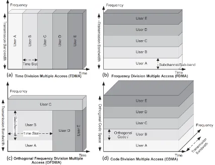
There are various multiple access schemes that have been used in cellular systems in the past few years which allow the network to share the available radio resources (i.e., time, frequency, code, and space) among a number of users in the cell in the downlink and uplink directions. Figure 2.1 illustrates the concept of resource sharing in various multiple access schemes (Ahmadi, 2011).
11
Figure 2.1: An illustration of different multiple access scheme concepts (Ahmadi, 2011).
2.2 Frequency Division Multiple Access (FDMA)
FDMA is the oldest, and conceptually most simple, multiaccess method. Each user is assigned a frequency (sub) band – i.e., a (usually contiguous) part of the available spectrum (see Figure 2.2). Hence, each user tunes its transmit and receive filters in order to successfully send and receive in its own sub-band, while filtering out what is transmitted elsewhere.
(a) (b)
12
[image:34.612.228.422.233.363.2]The assignment of frequency bands is usually done during call setup, and retained during the whole call. FDMA is usually combined with the Frequency Domain Duplexing (FDD) so that two frequency bands (with a fixed duplex distance) are assigned to each user: one for downlink (BS-to-MS) and one for uplink (MS-to-BS) communication (Benvenuto et al. 2011) and (Molisch, 2011).
Figure 2.2: Principle of frequency division multiple access (Molisch, 2011).
Pure FDMA is conceptually very simple, and has some advantages for implementation:
1. The transmitter (TX) and receiver (RX) require little digital signal processing. However, this is not so important in practice anymore, as the costs for digital processing are continuously decreasing.
2. (Temporal) synchronization is simple. Once synchronization has been established during the call setup, it is easy to maintain it by means of a simple tracking algorithm, as transmission occurs continuously.
13
1. Frequency synchronization and stability are difficult: for speech communications, each frequency subband is quite narrow (typically between 5 and 30 kHz). Local oscillators thus must be very accurate and stable; jitters in the carrier frequency result in adjacent channel interference. High spectral efficiency also requires the use of very steep filters to extract the desired signal. Both accurate oscillators and steep filters are expensive, and thus undesirable. If they are not admissible, guard bands can be used to mitigate filter requirements. This, however, reduces the spectral efficiency of the system (Molisch, 2011).
2. Sensitivity to fading: since each user is assigned a distinct frequency band, these bands are narrower than for other multi access methods (compare TDMA, CDMA) – i.e., 5–30 kHz. For such narrow subbands, fading is flat in practically all environments. This has the advantage that no equalization is required; the drawback is that there is no frequency diversity. Remember that frequency diversity is mainly provided by signal components that are more than one channel coherence bandwidth apart.
3. Sensitivity to random Frequency Modulation (FM): due to the narrow bandwidth, the system is sensitive to random FM. Thus, it is inversely proportional to the square of the bandwidth. On the positive side, appropriate signal-processing schemes can not only mitigate these effects but even exploit them to obtain time diversity. Note that the situation here is dual to wideband systems, where delay dispersion can be a drawback, but equalizers can turn them into an asset by exploiting frequency diversity.
14
It is for these reasons that FDMA is mostly used for the following applications:
1. Analog communications systems: here, FDMA is the only practicable multiple access method.
2. Combination of FDMA with other multiple access methods: the spectrum allocated for a service (or a network operator) is divided into larger subbands, each of which is used for serving a group of users.
3. High-data-rate systems: the disadvantages of FDMA are mostly relevant if each user requires only a small bandwidth – e.g., 20 kHz. The situation can be different for wireless Local Area Networks (LANs), where a single user requires a bandwidth on the order of 20 MHz, and only a few frequency channels are available.
2.3 Time Division Multiple Access (TDMA)
[image:36.612.235.419.531.662.2]For TDMA, different users transmit not at different frequencies but rather at different times (see Figure 2.3).
15
A time unit is subdivided into N timeslots of fixed duration, and each user is assigned one such timeslot. During the assigned timeslot, the user can transmit with a high data rate (as it can use the whole system bandwidth); subsequently, it remains silent for the next N − 1 timeslots, when other users take their turn. This process is then repeated periodically. At first glance, this approach has the same performance as FDMA: a user transmits only during 1/N of the available time, but then occupies N times the bandwidth. However, there are some important practical differences:
1. Users occupy a larger bandwidth. This allows them to exploit the frequency diversity available within the bandwidth allocated to the system; furthermore, the sensitivity to random FM is reduced. On the flipside, equalizers are required to combat Inter Symbol Interference (ISI) for most operating environments; this increases the effort needed for digital signal processing (Molisch, 2011).
2. Temporal guard intervals are required. A TX needs a finite amount of time to ramp up from 0-W output power to “full power” (typically between 100mW and 100 W). Furthermore, there has to be sufficient guard time to compensate for the runtime of the signal between the MS and BS. It is possible that one MS is far away from the BS, while the one that transmits in the subsequent timeslot is very close to the BS and thus has negligible runtime. As the signals from the two users must not overlap at the BS, the second MS must not transmit during the time it takes the first signal to propagate to the BS. Note, however, that there is no need for frequency guard bands, as each user completely fills up the assigned band (Molisch, 2011).
16
channel starts to change during one timeslot. In that case, the equalizer has to track the channel during transmission of a timeslot, which increases implementation effort. If the time between two timeslots assigned to one user is larger than coherence time, the channel has changed between these two timeslots, and a new channel estimate is required (Molisch, 2011).
4. For interference-limited systems, TDMA has a major advantage: during its period of inactivity, the MS can “listen” to transmission on other timeslots. This is especially useful for the preparation of handovers from one BS to another, when the MS has to find out whether a neighboring BS would offer better quality, and has communications channels available (Molisch, 2011).
5. TDMA schemes can be inefficient when some users do not have data to send as their slots will go unused in that case. There exist more sophisticated solutions where multiple slots can be allotted to a given user. However, this can be implemented at the price of some extra communication overhead. In general, the TDMA paradigm relies on a central controller to distribute the slot assignments. Further details and performance evaluation for these schemes are given in (Benvenuto et al. 2011).
2.4 Orthogonal Frequency Division Multiple Access (OFDMA)
In OFDMA, an OFDM symbol is constructed of sub-carriers, the number of which is determined by the FFT size. There are several sub-carrier types:
1. Data sub-carriers are used for data transmission.
17
3. Null subcarriers are not used for pilot/data transmission. The null sub-carriers are used for guard bands and DC sub-carrier. The number of sub-carriers used is always less than the FFT/IFFT size. The guard bands are used to allow spectrum sharing, and to reduce the adjacent channel interference and out-of-band emissions. The sampling frequency is selected to be greater than or equal to the channel bandwidth. In order to ensure that the number of time samples in a 5 ms radio frame is an integer and to further simplify the design of the analog transmit filter, the sampling frequency is scaled by a factor greater than one (Ahmadi, 2011).
The most popular application of combination access schemes is the uplink of 4th Generation of mobile communications Single Carrier-Frequency Division Multiple Access SC-FDMA which is OFDMA combined with TDMA. In other words, the spectral resources, as represented in the time/frequency plane, are assigned in a flexible manner to the different users. Furthermore, different users can have different data rates. The transmissions for a specific user are scheduled to happen in those frequency bands that offer the best propagation conditions, thus exploiting multiuser diversity (Molisch, 2011).
2.5 Code Division Multiple Access (CDMA)
18
associated to different users to guarantee the orthogonality between simultaneous transmission, thus obtaining a multiple user communication. Since different codewords are associated with different users, in CDMA each user is effectively exploiting a binary antipodal transmission scheme. Extensions to higher modulation formats as QPSK are also used (Benvenuto et al. 2011).
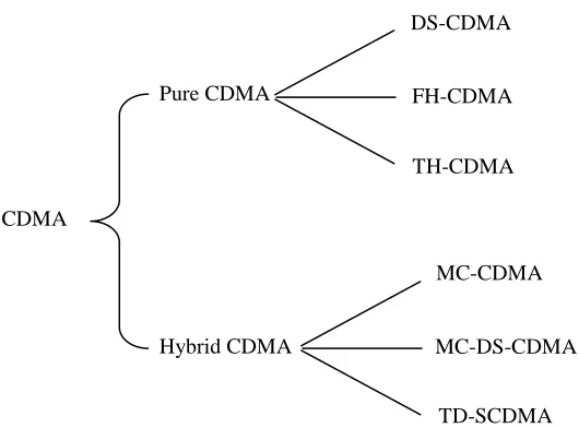
[image:40.612.174.439.289.485.2]According to the classification based on the modulation method used to obtain the spread spectrum signal, CDMA types are shown in Figure 2.4 and discussed as follows:
Figure 2.4: Classification of CDMA Techniques
CDMA
Hybrid CDMA Pure CDMA
DS-CDMA
FH-CDMA
TH-CDMA
MC-CDMA
MC-DS-CDMA
19
2.5.1 Direct Sequence-Code Division Multiple Access (DS-CDMA)
Nowadays, DS modulation has been used for many commercial communication systems (almost all 3G mobile cellular systems use DS-CDMA as their prime multiple access air-link architecture) and measurement instruments. It is reasonable to expect that DS modulation will continue to be a familiar form of spreading modulation scheme in the years to come due to its unique and desirable features. Characteristic of DS spreading modulation is just exactly that modulation of a carrier by a code sequence.
20
2.5.2 Frequency Hopping-Code Division Multiple Access (FH-CDMA)
Comparing to the DS-CDMA technique, the FH-CDMA technique is a relatively less widely used CDMA scheme in real applications. The reason for its less wide acceptance is owing to several factors. First, the FH technique requires a very accurate reference clock in the whole wireless system which uses the FH-CDMA technique for user separation. This accurate network-wide reference clock is very costly to implement using currently available digital technology.
Maybe in future the situation will be different with the advancement in micro-electronics technologies. Second, the hardware to implement an FH-CDMA is still much too complex compared to DS-CDMA under the same maximum data transmission rate constraint. Therefore, system designers still prefer DS-CDMA to FH-CDMA for most commercial wireless applications (Abu-Rgheff, 2007).
In frequency hopping CDMA, the transmission bandwidth is divided into frequency sub-bands, where the bandwidth of each sub-band is equal to the bandwidth of the information signal. A pseudo-random code is then used to select the sub-band, in which the information signal is transmitted and this sub-band changes periodically according to the code. There are two sub-categories of FH-CDMA:
1. Fast frequency hopping where one complete, or a fraction of the data symbol, is transmitted within the duration between carrier hops .Consequently for a binary system, the frequency hopping rate may exceed the data bit rate.
21
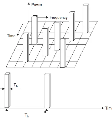
Figure 2.5 illustrates how the carrier frequency hops with time. Let time duration between hops be Th and data bit duration be denoted by Tb, then (Chen, 2007):
Th ≤ Tb for fast hopping (2.1)
[image:43.612.236.421.322.518.2]Th > Tb for slow hopping (2.2)
Figure 2.5: Carrier frequency hopping from one frequency to another (Chen, 2007).
22
synthesizer will work according to the hopping sequences generated by the code generator (Abu-Rgheff, 2007) and (Chen, 2007).
[image:44.612.152.506.370.594.2]Usually, the code generator can produce a great number of different patterns, each of which will be used by the synthesizer to generate a particular carrier, which will be multiplied with the data modulated signal in the mixer to produce an up-converted transmitting signal from the antenna. Therefore, the carrier frequency of the transmission signal is under the control of the code generator, which can also control the FH rate from one frequency to another. The hopping rate is a very important parameter in an FH-CDMA system, which will determine if it is a fast-hopping or a slow-hopping FH system (Abu-Rgheff, 2007).
Figure 2.6: Basic FH transmitter (Abu-Rgheff, 2007)
X
Modulator
Synthesizer
Code generator
m(t) FH signal
Main carrier
Clock
23
2.5.3 Time Hopping-Code Division Multiple Access (TH-CDMA)
The third CDMA technique, TH-CDMA, is found to be much less widely used than the previous two mainly due to its implementation difficulties and the hardware cost associated with its transmitter, which should provide an extremely high dynamic range and very high switching speed.
The TH technique, in fact, works in a very similar way as a digital modulation scheme called pulse position modulation (PPM) (Abu-Rgheff, 2007).
The TH-SS (Time Hopping Spread Spectrum) technologies are not as popular as the other two spread spectrum techniques, i.e. the DS-SS (Direct Sequence Spread Spectrum) and FH-SS (Frequency Hopping Spread Spectrum) techniques. The main reason is implementation difficulties, especially for the pulse generator, which is the core of a TH-SS system and should be able to produce a train of very narrow impulses with its width being at an order of nano-seconds. The pulse generator should also provide very good timing accuracy, such that the PPM can be effectively applied to code different SS sequences for multiple access.
The TH-SS technique seldom works independently in an SS system (except for the case of an ultra-wideband (UWB) system, a technology developed based on the TH technique). Instead, it works with some other SS modulation schemes, in particular the FH technique, which has been discussed in the previous section, to result in a time-frequency hopping SS scheme.
24
[image:46.612.104.538.211.408.2]time slots is transmitted depends on the code signal assigned to the user. Since a user transmits all of its data in one, instead of M, time slots, the frequency it needs for its transmission has increased by a factor M. A block diagram of a TH-CDMA system is given in Figure 2.7 (Jiang, Zhang, and Lu, 2009).
Figure 2.7: Block diagram of TH-CDMA transmitter and receiver (Abu-Rgheff, 2007).
2.5.4 Hybrid Code Division Multiple Access
The increasing demand for high data rate transmission for newly evolving wireless communications systems, has challenged the researchers to exploit new modulation, diversity and coding techniques to overcome the limited natural wireless resources: frequency and power (Elnoubi and Hashem, 2008).
Data modulator
Code generator
Carrier generator Slow
in
Fast out
Data demodulator
Fast in
Slow out
Code generator Carrier
generator
172
REFERENCES
Abu-Rgheff, M. A. (2007). Introduction to CDMA Wireless Communications. Elsevier. pp.164-224.
Ahmadi, S. (2011). Mobile WiMAX a Systems Approach to Understanding IEEE
802.16m Radio Access Technology. Elsevier Inc. pp.355-385.
Almeida, M. (2011).Vehicular technologies:increasing connectivity. Published by InTech. pp. 205-206.
Ameen, J. H. & Ismail, W. (2011). Multi-band carrier Code Division Multiple Access
for 4G mobile system with improved signal quality. World Applied Sciences
Journal. vol. 12. no.3. pp.330-335.
Amir, S. & Asif, M. (2011). Analytical study of MC-CDMA-TCM over multi-path
Rayleigh fading channel. International Conference on Computer Engineering
and Applications (IPCSIT). vol.2. pp.332-337.
Baig, I. & Jeoti, V. (2010). Novel Precoding Based PAPR reduction schemes for
localized OFDMA uplink of LTE –A. Journal of Telecommunication, Electronic
and Computer Engineering. vol. 2. no. 1. pp. 49-58.
Benvenuto, N. & Zorzi, M. (2011). Principles of Communications Networks and
Systems. John Wiley & Sons Ltd. pp. 335-606.
Bhange, D. N., Dhakulkar, P. P. & Deotale, T. G. (2013). Single carrier spread
spectrum technique for uplink. International Journal of Electronics
173
Chakkravarthy, S. P., Nagarajan, N. & Arthi, V. (2010). Selection based successive
interference cancellation for multicode multicarrier CDMA transceiver. Wseas
transactions on communications. vol.8. no.9. pp.463-472.
Chang, C. (2011). Sum Throughput-Improved Resource Allocation for LTE Uplink
Transmission. IEEE Vehicular Technology Conference (VTC Fall). pp.1.
Chang, C. (2012). An Interference-Avoidance Code Assignment Strategy for the Hierarchical Two-Dimensional-Spread MC-DS-CDMA System: A Prototype of
Cognitive Radio Femtocell System. IEEE Transactions on Vehicular
Technology. vol. 61. no. 1. pp.166-167.
Chen, H. (2007). The Next Generation CDMA Technologies. John Wiley & Sons. pp.7-13.
Chen, Y., Peng, I. & Lai, C. (2012). Study of Radio Resource Allocation Scheme for
Single Carrier FDMA in LTE Network. IEEE 75th Vehicular Technology
Conference (VTC Spring), pp.1-5.
Cho,Y. S., Kim J., Yang, W. Y. & Kang, C. G.( 2010). MIMO-OFDM wireless
communications with MATLAB. John Wiley, pp. 145-146.
D’Orazio, L., Sacchi, C., Donelli, M., Louveaux, J. & Vandendorpe, L. (2011). A Near-optimum multiuser receiver for STBCMC-CDMA systems based on minimum
conditional BER criterion and genetic algorithm-assisted channel estimation.
EURASIP Journal on Wireless Communications and Networking. pp. 1-13. Deng, J. & Liao, S. (2010). A Low-PAPR Multiplexed MC-CDMA system with
enhanced data rate over multipath channels. IEEE 71st Vehicular Technology
Conference (VTC 2010-Spring), pp. 1-5.
Deng, J. H. & Hwang, J. K. (2011). Novel low-PAPR parallel FSOK transceiver design
for MC-CDMA system over multipath fading channels. EURASIP Journal on
174
Develi, I. & Akdagli A. (2013). Approximate Expression of Bit Error Rate in Uplink
MC-CDMA Systems with Equal Gain Combining. Journal of Communications
and Networks, vol. 15, no. 1. pp. 25-30.
Develi, I. & Kockaya, K. (2010). BER performance simulation of generalized MC
DS-CDMA system with time-limited Blackman chip waveform. Journal of Radio
Engineering, vol. 19. no. 3. pp.403-407.
Dhivagar , B., Kuchi, K. & Giridhar, K. (2013). An iterative MIMO-DFE receiver with
MLD for uplink SC-FDMA. National Conference on Communications (NCC).
pp.1-4.
Dongkai, Y., Xin, Y., Kefei, L. & Qishan, Z. (2009). Performance analysis of PAPR in
MC-CDMA system. International Conference on Information Science and
Engineering (ICISE2009).pp. 2676- 2679.
Dubey, A. K., Vashistha, G. & Parveen. (2011). Reanalysis of BER for wavelet based
MC-CDMA communication. International Journal of Computer Science &
Management Studies. vol. 11. no. 1. pp.39-42.
El-Absi, M. A. & Hussein, M. T. (2011).A novel method to reduce peak-to-average power ratio (PAPR) in multicarrier code division multiple access (MC-CDMA).
International Journal of Computer and Electrical Engineering. vol3.no.2. pp.176-179.
Elnoubi, S. M. & Hashem, A. (2008). Error Rate Performance of MC DS-CDMA
systems Over Multiple-Input -Multiple Output Nakagami-M Fading channel.
IEEE Military Communications Conference (MILCOM). pp.1-7.
Faisal, M., Uddin, J. & Haider, I. H. (2012). Simulation based performance analysis of MC-CDMA and CDMA over Rayleigh fading channel. International Journal on Internet and Distributed Computing Systems. vol. 2. no. 1. pp. 120-122.
Fazel, K. & Kaiser, S. (2008). Multi-Carrier and Spread Spectrum Systems From
175
Figueiredo, N. d. & Linde, L. P. (2011). MC-CDMA with Blind Channel Estimation
and Adaptive Reception. Southern Africa Telecommunication Networks and
Applications Conference (SATNAC). pp.224-226.
Gergis, L. F. (2011). Performance of MC-MC CDMA systems with nonlinear models of
HPA. International Journal of Wireless & Mobile Networks (IJWMN). vol. 3.
no. 1. pp. 86-96.
Giannetti, F., Lottici, V.& Stupia, I. (2011) PAPR Analytical Characterization and
Reduced-PAPR Code Allocation Strategy for MC-CDMA Transmissions. IEEE
Transactions on Wireless Communications. Vol. 10, No. 1. pp. 219-227.
Gite, A. V., Khan, A. R. & Gulhane, S. M.(2013). Performance evaluation of
MC-CDMA system using delta modulation in ultra wide band channel. International
conference SDIWC. pp.379-385.
Glisic, S. G. (2006). Advanced wireless networks 4G technologies. John Wiley, pp. 32-36.
Gupta, V. & Tiwari, R. (2011). Performance analysis and simulation result of
MC-CDMA for AWGN channel and raleigh based on SNR/BER. International
Journal of Advanced Computer Research. vol.1. no.1. pp.13-18.
HA, T. T. (2011). Theory and design of digital communication systems. Cambridge University. pp.21-27.
Hanzo, L. & Keller, T. (2006). OFDM and MC-CDMA A Primer. John Wiley & Sons Ltd. pp.219-220.
Hara, S. & Prasad, R. (2003). Multicarrier Techniques for 4G Mobile Communications.
Artech House. London. pp.176-179.
Hernández, L. A. & Otero, M. G. (2009). User reservation approach for
peak-to-average power ratio reduction in MC-CDMA systems. Vehicular Technology
Conference (VTC). pp. 1-5.
Holma, H. & Toskala, A. (2009). LTE for UMTS–OFDMA and SC-FDMA Based Radio
176
Hwang, J. K., Tsai, Y. T. & Lia, J. D. (2011). highly re-configurable Instruments-in-Matlab Software-Defined Radio platform for 4G SC-FDMA signal
measurements and analysis. IEEE/SICE International Symposium on system
Integration (SII). pp.1374.
Ida, Y., Ahn, C., Kamio, T., Fujisaka, H. & Haeiwa, K. (2013). Variable splitting
transmission in multi-relay cooperative communications for SC-FDMA. 15th
International Conference on Advanced Communication Technology (ICACT), pp. 623-627.
Ida, Y., Ahn, C., Kamio, T., Fujisaka, H. & Haeiwa, K. (2013). Variable packet splitting transmission in multi-relay cooperative communications with DF and
DAF for SC-FDMA. EURASIP Journal on Wireless Communications and
Networking. vol. 64, no. 1. pp. 1-8.
Indumathi, Dr. G.& Joe, D. A. (2013). Design of Optimum Physical Layer Architecture
for a High Data Rate LTE Uplink Transceiver. International Conference on
Green High Performance Computing. pp.1-8.
Ipatov, V. P. (2005).Spread Spectrum and CDMA Principles and Applications. John Wiley & Sons. pp. xi.
Jacklin, N. & Zhi, D. (2013). A Linear Programming Based Tone Injection Algorithm
for PAPR Reduction of OFDM and Linearly Precoded Systems. IEEE
transactions on circuits and systems. vol. 60. no. 7. pp. 1937- 1945.
Jamalipour, A., Wada, T. & Yamazato, T. (2005). A Tutorial on multiple access
technologies for beyond 3G Mobile Networks. IEEE Communications
Magazine. pp.110-117.
Jiang, X., Zhang, C. & Lu, J. (2009). Time-frequency hopping sequences with three no
hit zones. Springer Wireless Network. pp. 455-461.
Kha, H. H., Tuan, H. D., Nguyen, H. H. & Pham, T. T. (2013). Optimization of cooperative beamforming for SC-FDMA Multi-User Multi-Relay networks by
tractable D.C. programming. IEEE Transactions on Signal Processing. vol. 61.
177
Kha, H.H., Tuan, H.D. &Nguyen, H.H.(2013). Joint Optimization of Source Power Allocation and Cooperative Beamforming for SC-FDMA User
Multi-Relay Networks. IEEE Transactions on Communications. VOL. 61. NO. 6. pp.
2248-2259.
Khan, F. (2009). LTE for 4G mobile broadband air interface technologies and
performance. Cambridge university press. pp.85-86.
Krouk, E. & Semenov, S. (2011). Modulation and Coding Techniques in Wireless
Communications. John Wiley & Sons Ltd. pp.358-459.
Kumar, D. & Chellappan, C. (2009). Efficient Resource Allocation in MC-CDMA
Cellular Wireless Networks to Support Multimedia Traffic. Journal of
Theoretical and Applied Information Technology. pp.625-627.
Kumar, P. S, Rasadurai, K. & Kumaratharan, N. (2013). LDPC coding for performance
enhancement of MC-CDMA system. International Journal of Advanced Trends
in Computer Science and Engineering. vol.2 .no.1. pp.1-5.
Kumaratharan, N., Dananjayan, P. & Padmavathy, M. (2008). Performance
Improvement Of Mc-Cdma System Through Dstbc Site Diversity. Journal of
Theoretical and Applied Information Technology. pp.1075-1082.
Manjith, R. Ramesh, S. C. & Majeed, M. M.I. (2010). PAPR reduction in OFDM &
MC-CDMA system using nonlinear companding techniques. IEEE region 8
international conference on computational technologies in electrical and electronics engineering (SIBIRCON). pp. 274-278.
Meenakshi, D., Prabha, S., Raajan, N. (2013). Performance analysis of OFCDM,
MC-CDMA and OFDM for wire-free. IEEE Conference on Information and
Communication Technologies (ICT 2013). pp. 451-455.
Mishra, A. R. (2004). Fundamentals of cellular network planning and optimisation
2G/2.5G/3G... evolution to 4G. John Wiley. pp.156-157.
178
Morelli, M. & Sanguinetti, L. (2005). Novel prefiltering technique for downlink
transmissions in TDD MC-CDMA systems. IEEE Transactions on wireless
communications. vol. 4. no. 5. pp. 2064- 2069.
Myung, H. G. & Goodman, D. J. (2008). Single Carrier FDMA a New air Interface for
Long Term Evolution. John Wiley & Sons Ltd. pp. 38-71.
Nagarajan, V. & Dananjayan, P. (2010). Performance Analysis of MIMO
MC-DS/CDMA system using chaotic spreading sequence. International Journal of
Computer and Electrical Engineering. vol. 2. no. 2. pp. 329-333.
Ng, B. K., Lam, C. T. (2013). On Maximizing the Performance of SC-FDMA systems
with rotated constellation. 9th International Wireless Communications and
Mobile Computing Conference (IWCMC). pp. 1699- 1704.
Nours, S. L., Nouvel, F. & Helard, J. (2004). Design and Implementation of
MC-CDMA Systems for FutureWireless Networks. EURASIP Journal on Applied
Signal Processing. pp. 1604–1606.
Otero, M. G. & Hernández, L. A. (2011). PAPR reduction in SFBC MIMO MC-CDMA
systems via user reservation. EURASIP Journal on Advances in Signal
Processing. vol. 9. no. 1. pp. 1-10
Prasad, R. (2004). OFDM for wireless communications systems. Artech House, Inc. pp. 198-201.
Presti, C. D., Metzger, A. G., Banbrook, H. M., Zampardi, P. J. & Asbeck, P. M. (2010). Efficiency improvement of a Handset WCDMA PA module using
adaptive digital predistortion. IEEE MTT-S International Microwave
Symposium Digest (MTT). pp. 804 - 807.
Qayyum, A., Khan, M. A., Umair, M. & Choudhry.M. A. S. (2013). Performance
analysis of LMS based MC-CDMA system, Information Technology &
179
Rasadurai, K., Kumar, P. S. & Kumaratharan, N. (2013). Performance Enhancement of
MC-CDMA System Using LDPC Codes. IEEE Conference on Information and
Communication Technologies (ICT 2013). pp.78-82.
Rindhe, U., Shah, D. C. & Narayankhedkar, S. K. (2011). OFDM and MC-CDMA for
4G Networks. 2nd International Conference and workshop on Emerging Trends
in Technology (ICWET). pp. 30-37.
Sarala, B. & Venkateswarulu, D. S. (2011).MC-CDMA PAPR reduction techniques
using discrete transforms and companding. International Journal of Distributed
and Parallel Systems (IJDPS) vol.2. no.6. pp.253-270.
Schmidt, B., Chi, N., Yien, P., Harris, C., Saripalle, U., Price, A., Brewer, S., Scelsi, Giuseppe, Slaviero, R. & Armstrong, J. (2006). Efficient algorithms for PAPR
reduction in OFDM transmitters implemented using Fixed-Point DSPs .IEEE
63rd Vehicular Technology Conference (VTC-Spring). vol. 4. pp.2023-2027. Schulze, H. & Lǜders, C. (2005). Theory and Applications of OFDM and CDMA
Wideband Wireless Communications. John Wiley & Sons. pp.265.
Shabbir, M. S. & Ashraf M. A. (2011). SAFNAQ, an algorithm for transmission power
allocation in MCCDM. International Conference on Computer and Software
Modeling (IPCSIT). vol.14. pp.202-207.
Sivanesskumar, S. & Sukanesh, R. (2009). Performance Analysis of Multi-Carrier
Code Division Multiple Access System under Clipping Noise. European Journal
of Scientific Research. vol. 38. no.4. pp. 590–595.
Sureshkumar, K., Rajalakshmi1, R. & Vetrikanimozhi, A. (2011). Channel estimation
for MIMO MC-CDMA systems. International Journal of Distributed and Parallel
Systems (IJDPS). vol.2. no.6. pp. 347-355.
Taha, A. M., Abu Ali, N. & Hassanein, H. S. (2012).LTE, LTE-Advanced and WiMAX
180
Thuakaew, S. & Chayratsami, P. (2013). The Optimum Ring Ratio of 16-APSK in LTE
Uplink over Nonlinear System. 15th International Conference on Advanced
Communication Technology (ICACT). pp.805-809.
Wen, M., Cheng, X., Yin, X., Yang, L. & B. Jiao. (2013). A General Framework for BER Analysis of OFDMA and Zero-Forcing Interleaved SC-FDMA over
Nakagami-m Fading Channels with Arbitrary m. IEEE Wireless
Communications Letters. vol. 2. no. 4.pp. 395-398.
Wesołowski, K. (2009). Introduction to digital communication systems. John Wiley, pp. 529-530.
XU, B. & Lianfeng, S. (2008). A New Synchronization Protocol on the Convergence of
3G cellular network and manet. International Journal of Advanced Computer
Research. vol.1. no.1. pp.1-2.
Yang, L., You, M. & Li, J. (2009). Optimized spreading code reallocation technique
for PAPR reduction in MC-CDMA systems. IEEE Communications Society.
pp.1-6.
Yu, N. Y. (2010).A Theoretical study of Peak-to-Average Power Ratio in reed-muller
coded multicarrier CDMA. IEEE Conference Information Sciences and Systems