Grasping Analysis for a 3-Finger Adaptive Robot
Gripper
Amirul Syafiq Sadun1, Jamaludin Jalani2, and Faizal Jamil3 Department of Electrical Engineering Technology
Faculty of Engineering Technology, Universiti Tun Hussein Onn Malaysia Batu Pahat, Johor, Malaysia
1[email protected], 2[email protected], 3[email protected]
Abstract— A 3- Finger Adaptive Robot Gripper is an advanced robotic research that provides a robotic hand-like capabilities due to its flexibility and versatility. However, the grasping performance has to be analyzed and monitored based on the motor encoder, motor current, and force feedback so that the finger position and grasping force can be effectively controlled. This paper provides an open-loop grasping analysis for a 3-Finger Adaptive Robot Gripper. A series of grasping tests has been conducted to demonstrate the robot capabilities and functionalities. Different stiffness levels of the grasped objects have been chosen to demonstrate the grasping ability. In the experiment, a Modbus RTU protocol and Matlab/Simulink are used as communication and control platform. A specially modified interlink FSR sensor is proposed where a special plastic cover has been developed to enhance the sensor sensitivity. The Arduino IO Package is employed to interface the sensor and Matlab/Simulink. The results show that the significant relationships between finger position, motor current, and force sensor are found and the results can be used for a proper grasping performance.
Keywords—3-finger adaptive robot gripper; motor current; FSR force sensor; encoder position; open-loop;
I. INTRODUCTION
Underactuated robot hands have been extensively studied over the last few years. The mechanism provides simplistic designs and opportunities to explore new ideas for robotic fingers. It also enables robust and adaptive power grasping which improves the precision grasping for object manipulation. In modern robotic systems, grasping and manipulation skills are the core elements which are involved in unstructured environments (i.e. active and passive compliance). It is important to understand the performance of robotic hands during the grasping process before implementing it with a high complexity system or controller (i.e. closed loop environment). Thus, an open loop grasping analysis is essential to identify robot performance characteristics. The same approach was used in [1], [2] and [3] and it is found that the open loop grasping analysis is simple but yet effective way to understand the behaviors of the robotic hand during multiple grasping operations.
Many robotic hands have been developed mainly for mimicking the capabilities and functionalities of human hand [4]-[5]. However, none of these robots so far able to fully copy due to the complexity of human hand structure. Recently, a ROBOTIQ company has introduced an underactuated robot
hand called a 3-finger adaptive robot gripper. Although the size is bigger than the human hand, the robot gripper was still useful for the application in advanced manufacturing and robotic research. In brief, the robot encompasses of four (4) actuators and adaptive joint mechanisms. Its flexibility and versatility allows the gripper to pick up any object of any shape safely. This feature certainly provides the flexibility to the researchers for enhancing and simplifying their control design [6]. The robot can be conveniently communicated with robot controller such as Ethernet/IP, TCP/IP and Modbus RTU. In addition, the Matlab/Simulink can also be used to develop the control algorithm. The 3-finger adaptive robot gripper is shown in Fig. 1.
Fig. 1. A 3-Finger Adaptive Robot Gripper by ROBOTIQ
This paper provides an open-loop grasping analysis for the 3-Finger Adaptive Robot Gripper. The feedback information from motor encoder, motor current and force sensor are important aspects to be analyzed for monitoring the grasping performance.A series of grasping test has been conducted based on different object stiffness such a sponge and a rubber ball.The external force sensor is introduced by incorporating the low cost interlink FSR sensors. A modified plastic cover has been proposed to enhance the sensor sensitivity. Providing such information is the steps for implementing active compliant control on a 3-Finger Adaptive Robot Gripper in the future.
II. ROBOT FEATURES AND GRASPING MODE
joint is driven by the underactuated mechanism (elastic tendons) as shown in Fig. 2[7]. These encoders provide useful information, particularly for positioning and motion control of each Robotiq finger.
Passive Joints
ɭ
2ɭ
1ɭ
3Elastic Tendons
Active
[image:2.595.116.251.111.240.2]Joints
ɭ
0Fig. 2. Active and Passive Joint for 3-Finger Adaptive Robot Gripper
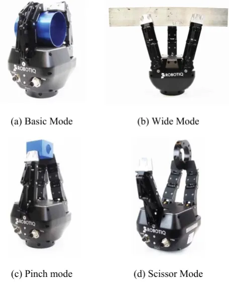
Moreover, the grasping force and speed can be pre-set where the robot has the capability to produce grasping force up to 60N. There are four (4) different grasping modes can be used to test the grasping performance. First, basic mode for objects that have one dimension longer than the other two.Second,
wide mode is optimal for gripping round or large objects; third,
pinch mode is used for small objects that have to be picked precisely and fourth, scissor mode is used primarily for tiny objects. This mode is less powerful than the other three modes, but is precise. In scissor mode, it is not possible to surround an object (see Fig. 3 and [8] for details). In this study, only basic mode, wide mode and pinch mode are considered.
(a) Basic Mode (b) Wide Mode
[image:2.595.317.543.231.359.2](c) Pinch mode (d) Scissor Mode
Fig. 3. Robot Grasping Modes
III. EXPERIMENTAL SETUP
A. Hardware Setup
Fig. 4 shows the general hardware setup for the experiment. The setup is simple and straight forward and did not require any “third party” hardware. The robot was controlled using Modbus RTU communication protocol via Matlab/Simulink Instrument Control Toolbox. It was then connected to a computer (laptop) via USB cable. The setup also consists of Arduino UNO which acts as a DAQ device. The analog input from the sensors are connected to Arduino ADC (Analog to Digital) pin and the data were then acquired using the Simulink Arduino IO Package. The robot and Arduino UNO were executed in the same Simulink program (with 2 different USB COM ports.
Force Sensor
3 Finger Adaptive Robot
Modbus
RTU MATLAB
SIMULINK
Arduino UNO
Serial USB USB
Analog Input
Fig. 4. Hardware Setup
Joint Angular Position
For this study, only the angular position for link 1 was considered for the grasping operations. The desired position of each finger is based on the joint angle of link 1 (ɭ1). Referring to Fig. 5, θɭ1 is the joint angle with reference to the robot’s palm axis. It is known that the joint angular position, θɭ1 for each robot finger is between 65˚ (minimum) to 125˚ (maximum).
Robot Palm
ɭ2
ɭ 3
θ
ɭ1 [image:2.595.52.280.416.696.2]ɭ 1
Fig. 5. Robot Finger Joint Angular Position (Link 1)
B. FSR Force Sensor Setup
[image:2.595.354.509.478.569.2]is essential. The general specifications show that the detection force is ranged between 1N to 100N [11]. However, capturing higher force (more than 35N) can be troublesome. For this, the researcher has developed a 3D printed plastic cover as shown in Fig. 6. This plastic cover is designed mainly to enhance the force distribution during grasping. The FSR sensor and the plastic cover are mounted together by using double sided tape. The sensors are then placed on each robotic finger tip as shown in Fig. 7.
Standard FSR Sensor
Contact Force
Standard FSR Sensor Plastic
[image:3.595.43.290.170.285.2]Cover
Fig. 6. A 3D printed plastic cover for the FSR sensor
FINGER A FINGER C
[image:3.595.100.224.317.430.2]FINGER B
Fig. 7. FSR Sensor with 3D Printed Plastic Cover
-20 0 20 40 60 80
0 5 10
FOR
C
E (
N
)
TIME (S)
FINGER A
Standard FSR Sensor FSR with Plastic Cover
-20 0 20 40 60 80
0 5 10
FORC
E
(N)
TIME (S)
FINGER B
Standard FSR Sensor FSR with Plastic Cover
-20 0 20 40 60 80
0 5 10
FO
R
C
E
(N
)
TIME (S)
FINGER C
Standard FSR Sensor FSR with Plastic Cover
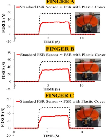
Fig. 8. FSR Sensor with 3D Printed Plastic Cover Placement
A preliminary test was carried out to observe the performance of the FSR sensors with and without (i.e. a standard FSR sensor) the plastic cover. A low stiffness spongy ball is used for the test object. The maximum speed and force (approximately 60N on the finger tip) are set and the results can be seen in Fig. 8. It is found that the standard FSR sensors are not capable of detecting a grasping force higher than 35N. The thinness of FSR sensors makes it harder to detect the pressure from a soft object (i.e. a low stiffness ball). In contrast, the FSR sensor with plastic cover improved significantly the reading where the captured data are approaching 60N. The results clearly show that the FSR sensors with 3D plastic covers are useful for detecting a wider range of forces. This technique is certainly very helpful when the low cost sensors are used on robotic hands, particularly on a 3 Finger Adaptive Robot Gripper.
C. The Open Loop System
An open loop control system has been set up for a 3 Finger Adaptive Robot Gripper to perform a grasping analysis as illustrated in Fig. 9. The desired position (joint angle) of each finger is manually controlled by using Matlab/Simulink. The desired position is based on the size and shape of the grasped object. The feedback data, such as an encoder, motor current, and force value are also required for real time analysis.
Joint Angle
Finger Position (θɭ1)
Force (N)
Motor Current (mA)
INPUT OUTPUT
[image:3.595.332.530.351.470.2]θɭ1
Fig. 9. Open Loop Robotic Hand
IV. GRASPING ANALYSIS AND DISCUSSION
A. Grasping Variations
There are two (2) different scenarios can be expected when executing the grasping test. First, when grasping a soft object, the same level of force is produced by each fingertip. This allows each finger (finger A, finger B and finger C) stops at the same desired position. Second, when grasping a hard object, different force level is produced by each finger. Refer Fig. 10 for a better insight of grasping variations. In order to demonstrate this scenario, two (2) different objects which have similar size but different stiffness are selected (see Fig. 11). In the case of the 3-finger adaptive robot gripper, the grasping is driven by the elastic tendons that are controlled by the actuators. This actuator is mounted to the first finger link, ɭ1 (see Fig. 5).
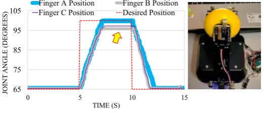
[image:3.595.75.253.459.689.2]This implies that the object has produced a low force level and consequently driven all fingers to the desired position easily. On the other hand, in the case of grasping for the high stiffness ball, only finger A is able reaching to the desired position as compared to finger B and finger C (see Fig. 12 (b)). This scenario obviously represents the case as depicted in Fig. 10 (b). According to [5], this grasping variation occurred (at a different desired position) was due to the summation of force from two fingers (in this case finger B and finger C).
The additional grasping test has been carried out by employing the wide grasping mode (usually used for power grasping). A hard rubber ball which has a 13 cm diameter is used for the test object. The desired position is set to 85 degrees. The results show that only finger B and finger C follow the set point satisfactorily while finger A only achieves a set point of 78 degrees. However, the grasped object is still in stable condition and the performance is shown in Fig. 13.
FINGER A FINGER B FINGER C
F
F
F
FINGER A FINGER B FINGER C
F F
F LOW STIFFNESS
OBJECT
HIGH STIFFNESS OBJECT IDEAL GRASPING GRASPING VARIATIONS
(a) a soft object (b) a hard object Fig. 10. Grasping Variations
[image:4.595.308.570.58.170.2]LOW STIFFNESS HIGH STIFFNESS
Fig. 11. Grasping Object (Spongy Ball)
65 75 85 95 105
0 5 10 15
JO
IN
T
A
N
G
LE
(DEG
R
EES
)
TIME (S)
Finger A Position Finger B Position Finger C Position Desired Position
(a) Low stiffness ball
65 75 85 95 105
0 5 10 15
JO
INT
A
NGLE
(DE
G
REES)
TIME (S)
Finger A Position Finger B Position Finger C Position Desired Position
(b) High stiffness ball
Fig. 12. Desired Position vs. Actual Position
65 70 75 80 85 90
0 5 10 15
JO
IN
T
A
N
G
LE
(D
EG
R
E
E
S
)
TIME (S)
Finger A Position Finger B Position
[image:4.595.324.545.231.357.2]Finger C Position Desired Position
Fig. 13. Power Grasping in “wide mode”
B. Force Analysis
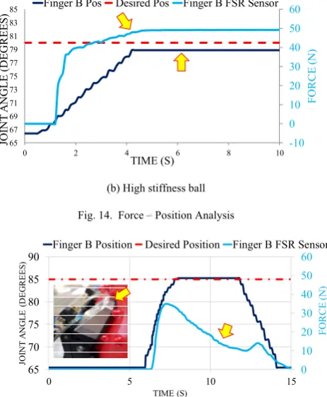
This section provides the grasping analysis with respect to the external force. The analysis will be based on the pinch grasping mode and two (2) different balls are considered (a soft and a hard ball). The desired position is set to 80 degrees and only performance of finger B is observed for simplicity. Fig. 14 demonstrates the performance of the FSR sensor when grasping a soft ball (a low stiffness ball). It is found that the grasping position of finger B follows a set point satisfactorily when an external force is applied. However, the force level is maintained at 40N. The results are different when grasping a hard ball where the grasping position of finger B is below a set point (reaching approximately 79 degrees). Meanwhile, the force level is maintained at 49N.
-10 0 10 20 30 40 50 60
65 67 69 71 73 75 77 79 81 83 85
0 2 4 6 8 10
TIME (S)
FO
RCE
(N
)
JO
IN
T
A
N
G
L
E
(D
EG
R
E
ES
) Finger B Pos Desired Pos Finger B FSR Sensor
[image:4.595.309.552.563.686.2]-10 0 10 20 30 40 50 60 65 67 69 71 73 75 77 79 81 83 85
0 2 4 6 8 10
TIME (S) F O RCE (N ) JO IN T A N G L E (D EG R E ES
) Finger B Pos Desired Pos Finger B FSR Sensor
[image:5.595.52.284.64.345.2](b) High stiffness ball
Fig. 14. Force – Position Analysis
0 10 20 30 40 50 60 65 70 75 80 85 90
0 5 10 15
F O RCE (N ) JO IN T A N G L E ( D EG REES ) TIME (S)
[image:5.595.318.553.172.296.2]Finger B Position Desired Position Finger B FSR Sensor
Fig. 15. Object Surface Slippage Results
Moreover, Fig. 15 demonstrates the slippage of the grasped object during grasping. The slippage occurs due to the uneven surface ball. It can be seen that the force level dropped from 35N to 0N when the ball slipping. Similar experimental test on slippage can be found in [12].
C. Motor Current Analysis
This section provides the grasping analysis with respect to the actuator’s motor current. The motor current is recorded based on the “no load” grasping condition. The desired position is set to 90 degrees. Interestingly, the current dropped to 0 mA when the desired position is achieved (spans of 3.2 s to 5.8 s). Meanwhile, the average motor current is 0.75 mA during grasping (X) and ungrasping (Y). Fig. 16 shows the detail grasping analysis and current level. The difference of current level produced during grasping and ungrasping has been addressed in [13].
0 1 2 3 4 5 65 70 75 80 85 90 95 100
0 2 4 6 8
MO T O R CU RR E N T JO INT A N G LE (D EG R E E S) TIME (S)
Finger Position Motor Current
(x 10
2 mA)
[image:5.595.320.544.554.685.2]X Y
Fig. 16. Grasping and Ungrasping during “no load”
Moreover, Fig. 17 shows the correlation between force and motor current. Their characteristics are summarised in Table I. Additionaly, the relationship between motor current and force sensor is also recorded. The results are depicted in Fig. 18. The robot finger and object are in contact starting from point “c”. As the finger continues to grasp, the contact force and the motor current increase proportionally. Once the finger reaches the desired grasping position, the motor current drastically drops to 0 mA at point “c”. Then the finger stops at period 6.5 seconds.
-0.4 0.6 1.6 2.6 3.6 -5 5 15 25 35 45 55 65
4 6 8 10 12
M O T O R C U RRENT FO RCE (N ) TIME (S)
FSR Sensor Motor Current
(mA ) a b c d e
Fig. 17. Force – Motor Current Results
TABLE I. CHARACTERISTIC SUMMARY
Point Description
a Robot finger starts moving
b Robot finger and object contact point
c Robot finger reaches the maximum position (i.e. maximum force)
d Robot finger stops (i.e. finger reaches the desired position)
e Object resistance decreases during ungrasping operation
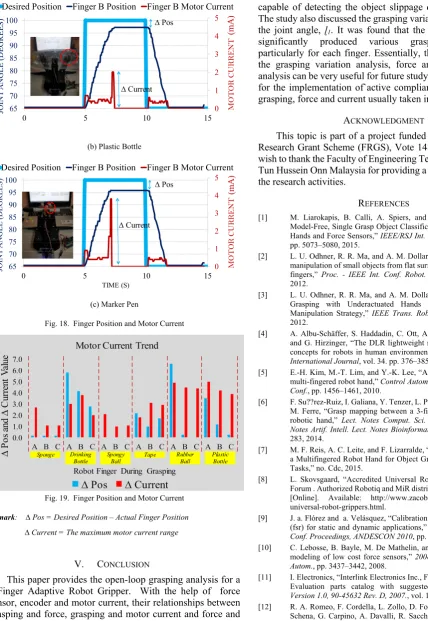
It can also be observed that the motor current has a different amplitude for different grasping objects. The test on three (3) different objects, namely a sponge, a plastic bottle and a pen
will verify this scenario (see Fig. 18). Obviously, the stiffer object (i.e. a pen) produced the highest current amplitude, followed by the plastic bottle and the sponge. In addition, Fig. 19 summarizes the relationship between ∆ Pos and ∆ Current for finger A, finger B and finger C based on six (6) different objects. 0 1 2 3 4 5 65 70 75 80 85 90 95 100
0 5 10 15
MO T O R C U RR E N T JO IN T A N G L E (D E G R E ES )
Desired Position Finger B Position Finger B Motor Current
(mA
)
∆ Current ∆ Pos
[image:5.595.42.287.586.707.2]
0 1 2 3 4 5
65 70 75 80 85 90 95 100
0 5 10 15
MO
T
O
R
CUR
R
E
N
T
JO
IN
T
A
N
G
LE
(D
EG
R
EES)
Desired Position Finger B Position Finger B Motor Current
(mA
)
∆ Pos
∆ Current
(b) Plastic Bottle
0 1 2 3 4 5
65 70 75 80 85 90 95 100
0 5 10 15
M
O
T
O
R C
U
RR
EN
T
JO
IN
T
A
N
G
L
E
(D
E
G
R
E
E
S)
TIME (S)
Desired Position Finger B Position Finger B Motor Current
(m
A
)
∆ Pos
∆ Current
(c) Marker Pen
Fig. 18. Finger Position and Motor Current
0.0 1.0 2.0 3.0 4.0 5.0 6.0 7.0
A B C A B C A B C A B C A B C A B C
∆
Pos
an
d
∆
C
ur
ren
t
V
al
ue
Robot Finger During Grasping
Motor Current Trend
∆ Pos ∆ Current
Sponge Drinking Bottle
Spongy Ball
Tape Rubber Ball
[image:6.595.48.477.53.675.2]Plastic Bottle
Fig. 19. Finger Position and Motor Current
Remark: ∆ Pos = Desired Position – Actual Finger Position
∆ Current = The maximum motor current range
V. CONCLUSION
This paper provides the open-loop grasping analysis for a 3-Finger Adaptive Robot Gripper. With the help of force sensor, encoder and motor current, their relationships between grasping and force, grasping and motor current and force and motor current can be found. Obviously, the stiffness of the grasped object affect the grasping performance. Moreover, the performance of the FSR sensor can be enhanced by introducing a modified plastic cover. Additionally, the force sensors are
capable of detecting the object slippage during the grasping. The study also discussed the grasping variations with respect to the joint angle, ɭ1. It was found that the power grasping has
significantly produced various grasping performance, particularly for each finger. Essentially, the information from the grasping variation analysis, force analysis, and current analysis can be very useful for future study. This is in particular for the implementation of`active compliant control where the grasping, force and current usually taken into considerations.
ACKNOWLEDGMENT
This topic is part of a project funded by the Fundamental Research Grant Scheme (FRGS), Vote 1480. The authors also wish to thank the Faculty of Engineering Technology, Universiti Tun Hussein Onn Malaysia for providing a platform to carry out the research activities.
REFERENCES
[1] M. Liarokapis, B. Calli, A. Spiers, and A. Dollar, “Unplanned, Model-Free, Single Grasp Object Classification with Underactuated Hands and Force Sensors,” IEEE/RSJ Int. Conf. Intell. Robot. Syst., pp. 5073–5080, 2015.
[2] L. U. Odhner, R. R. Ma, and A. M. Dollar, “Precision grasping and manipulation of small objects from flat surfaces using underactuated fingers,” Proc. - IEEE Int. Conf. Robot. Autom., pp. 2830–2835, 2012.
[3] L. U. Odhner, R. R. Ma, and A. M. Dollar, “Open-Loop Precision Grasping with Underactuated Hands Inspired by a Human Manipulation Strategy,” IEEE Trans. Robot., vol. 10, no. 3, p. 9, 2012.
[4] A. Albu-Schäffer, S. Haddadin, C. Ott, A. Stemmer, T. Wimböck, and G. Hirzinger, “The DLR lightweight robot: design and control concepts for robots in human environments,” Industrial Robot: An International Journal, vol. 34. pp. 376–385, 2007.
[5] E.-H. Kim, M.-T. Lim, and Y.-K. Lee, “Analysis grasp stability for multi-fingered robot hand,” Control Autom. Syst. (ICCAS), 2010 Int. Conf., pp. 1456–1461, 2010.
[6] F. Su??rez-Ruiz, I. Galiana, Y. Tenzer, L. P. Jentoft, R. D. Howe, and M. Ferre, “Grasp mapping between a 3-finger haptic device and a robotic hand,” Lect. Notes Comput. Sci. (including Subser. Lect. Notes Artif. Intell. Lect. Notes Bioinformatics), vol. 8618, pp. 275– 283, 2014.
[7] M. F. Reis, A. C. Leite, and F. Lizarralde, “Modeling and Control of a Multifingered Robot Hand for Object Grasping and Manipulation Tasks,” no. Cdc, 2015.
[8] L. Skovsgaard, “Accredited Universal Robots support Centre and Forum . Authorized Robotiq and MiR distributor . Robotiq grippers.” [Online]. Available: http://www.zacobria.com/robotiq-zacobria-universal-robot-grippers.html.
[9] J. a. Flórez and a. Velásquez, “Calibration of force sensing resistors (fsr) for static and dynamic applications,” 2010 IEEE ANDESCON Conf. Proceedings, ANDESCON 2010, pp. 2–7, 2010.
[10] C. Lebosse, B. Bayle, M. De Mathelin, and P. Renaud, “Nonlinear modeling of low cost force sensors,” 2008 IEEE Int. Conf. Robot. Autom., pp. 3437–3442, 2008.
[11] I. Electronics, “Interlink Electronics Inc., FSR integration Guide and Evaluation parts catalog with suggested Electrical interfaces,” Version 1.0, 90-45632 Rev. D, 2007., vol. 1.0, 2007.
[12] R. A. Romeo, F. Cordella, L. Zollo, D. Formica, P. Saccomandi, E. Schena, G. Carpino, A. Davalli, R. Sacchetti, and E. Guglielmelli, “Development and preliminary testing of an instrumented object for force analysis during grasping,” pp. 6720–6723, 2015.