EDFA WDM Optical Network using GFF
Shweta Bharti
M. Tech, Digital Communication, (Govt. Women Engg. College, Ajmer), Rajasthan, India
ABSTRACT
This paper describes the model and simulation of EDFA WDM optical network using GFF (Gain flattening filter). The proposed model consists of input source, pumping sources, isolators, EDFA, WDM multiplexers, GFF, pin photo detector, low pass Bessel filter, 3R generator, BER analyzer. The proposed model is simulated on opt system 7.In this paper the proposed model represent EDFA flattened gain dynamics and reduced noise figure. This is useful in network reconfiguration and Multi-vendor networks.
Keywords: EDFA, WDM, isolator, gain, optical communication, optical fiber amplifier, Gain flattening filter.
INTRODUCTION
In today’s world, communication demands are increased by the introduction of different new communication techniques [1]. Now a days internet service requires large bandwidth so EDFA’s are used with WDM technology to achieve this large bandwidth and to deliver good quality of signals to users without increasing the cost [2]. EDFA are used as pre-, line- and power amplifiers providing multi channel amplification with insignificant cross talks. Hence in this work we are providing EDFA’s with wide and Flat Gain spectrums using GFF and also reducing the Noise figure. A typical Fixed Gain EDFA is a combination of length of Erbium Doped Fiber (EDF), and a Gain Flattening Filter (GFF). EDF is followed by GFF. The amplifier is operated like that all time this EDF provides a fixed amount of Gain, while the GFF is designed to provide a spectral attenuation profile that exactly compensates for the spectral gain profile of the EDF. In this way the spectrum at the output of the EDFA is flattened [3].
EDFA’s Basics & Structure
EDFA technology is the technology in which Erbium Doped Fiber (EDF), a conventional Silica fiber doped with Erbium. When this Erbium fiber is illuminated with light energy by a suitable wavelength of either 980nm or 1480nm then this Er ion excited to a higher energy levels of long life time Inter mediate state. After a specific time it decays back to the ground state and emitting light within the 1525-1565 nm bands. If the light signal is already exist within the 1525-1565nm band, then this stimulates the decay process which is called stimulated emission which produces an additional light energy. Thus, if a pump wavelength and a signal wavelength both are propagating through an EDF, then energy transfer will occur via the Erbium from the pump wavelength to the signal wavelength, resulting in signal amplification. Basic elements of an EDFA are shown schematically in Fig. 1.
Fig 1: Scheme of Erbium-Doped fibre amplifier
In the above diagram the laser diode generates a high powered beam of light at a wavelength such that the erbium
WDM Technology
Wavelength-division multiplexing (WDM) is a technology through which more than one optical channel can be transmitted on same at different wavelengths on a single optical fiber. Optical network using WDM is widely used in present telecommunication networks. Wavelength division multiplexing (WDM) techniques combined with erbium-doped fiber amplifier (EDFA) improves the capacity of light wave transmission, provides high capacity and also improves the flexibility of optical network technology.
Gain Flatenning Filter
A typical EDFA contains a length of Erbium Doped Fiber (EDF), followed by a Gain Flattening Filter (GFF). The amplifier is operated such that the EDF always provides a fixed amount of Gain, while the GFF is designed to have a spectral attenuation profile that exactly compensates for the spectral gain profile of the EDF. In this way the
spectrum at the output of the EDFA is flattened [3]. In a multi-channel WDM amplifier, a Gain Flattening Filter
(GFF) is usually placed after the outputisolator in order to flatten the gain spectrum as shown in fig 2.
Fig. 2: Diagram of a typical single stage EDFA
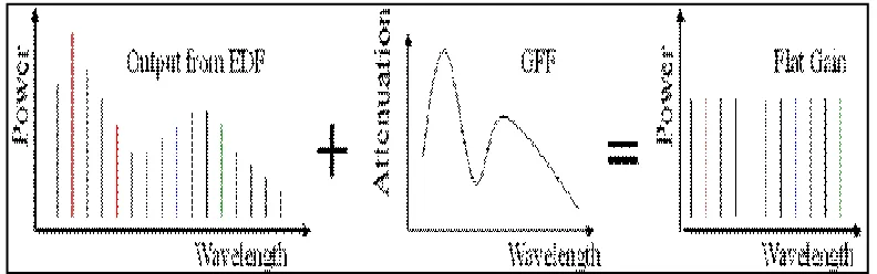
As explained earlier the attenuation spectrum of the GFF isdesigned to match the Gain spectrum of the EDF, such
that the combinationof the two produces a flat gain as shown in fig 3. If the amplifier has operate on another gain,
the GFF will not exactly compensate the gain profile of the EDF, and the output of the amplifier will no longer remain flattened. However, for a given length of EDF the gain profile can change drastically as a function of gain, to compensate for such a high gain tilt the GFF would need to attenuate the higher gain wavelengths by a very large amount, thus making the amplifier very inefficient
.
Fig 3: Use of a Gain Flattened Filter (GFF) to achieve a flat gain spectrum
Related Work
From very earlier Erbium Doped Fiber Amplifiers (EDFA) has been a target of several improvements. In optical Networks, by using EDFA’s it made possible to extend the transmission distances and the capacity of the networks. The paper [4] proposed an approach to EDFA gain with output power control and a power monitoring scheme for fault detection in WDM Networks. These techniques employ a power stabilized control channel, while the EDFA
of EDFA, which proposed to efficiently amplify high and low power level signals. The small signal gain can be improved by more than 5 dB with the use the double pass configuration. This paper [3] represents a composite EDFA configuration in which an optical isolator has been used and investigated highly efficient amplifier configurations with total high gain and narrow ASE spectrum. This paper [6] proposed an EDFA pumped in the range of 660nm and 820nm bands of wavelength and increased the signal power and gain. This paper [7] presents amplifier’s gain and noise power which appear in the signal to noise ratio expression, are computed in the form of the internal parameters from simulations and are shown to contribute to its improvement. This paper discusses [8] a new approach for a hybrid gain controlled EDFA based on a complementary actuation of the optical and electronic gain control technique with suppressed transients. This paper [9] discussed that without noise figure degradation of L-Band EDFA with 1480 nm power conversion efficiency and improvement without noise figure degradation.
Simulation
In this paper we proposed a model of EDFA-WDM optical network using GFF .
Fig 4: layout of EDFA WDM optical network using GFF
This model is simulated on optisystem 7 software. Fig 4 shows the stimulated model of EDFA-WDM optical network using GFF on optisystem 7 .In this fig4. WDM transmitter is used with 16 output channels, ideal multiplexers to multiplex these 16 channels. The input power of transmitter is -26 dbm. Two isolators is used. The purpose of these isolators is to avoid amplified spontaneous emissions and prevent signals to propagating in a backward direction. The pump power with 980 nm is used to excite erbium ion to higher level. The GFF is used after isolator to flatten the gain spectrum.
Result and Analysis
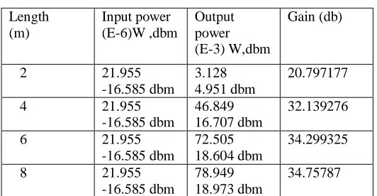
The reference pump power of 150mw is used to find out the optimal length. Table 1 shows the input power, output power and gain of the optical network by varying the length of the EDF.
Table 1
Length (m)
Input power (E-6)W ,dbm
Output power (E-3) W,dbm
Gain (db)
2 21.955
-16.585 dbm
3.128 4.951 dbm
20.797177
4 21.955
-16.585 dbm
46.849 16.707 dbm
32.139276
6 21.955
-16.585 dbm
72.505 18.604 dbm
34.299325
8 21.955
-16.585 dbm
78.949 18.973 dbm
10 21.955 -16.585 dbm
79.647 19.012dbm
34.575486
12 21.955
-16.585 dbm
78.953 18.974dbm
34.057521
14 21.955
-16.585 dbm
77.955 18.918 dbm
33.279661
16 21.955
-16.585 dbm
76.023 18.863 dbm
32.209539
18 21.955
-16.585 dbm
76.023 18.809 dbm
30.73371
20 21.955
-16.585 dbm
75.198 18.762 dbm
28.649279
22 21.955
-16.585 dbm
74.573 18.726 dbm
25.454655
The optimal length is 10m because maximum output power is obtained at 10m and after that output power is going to be reduce. Also the Max Q factor , Min BER, Eye height is obtained at 6m, 8m, 10m on the transmission port of GFF.
Table 2
Length (m) Max
Q Factor
Min BER Eye Height
6 2.304 .00877005 -0.00083445
8 2.13291 .00967001 -0.00127425
10 2.38564 .00631474 -.000842516
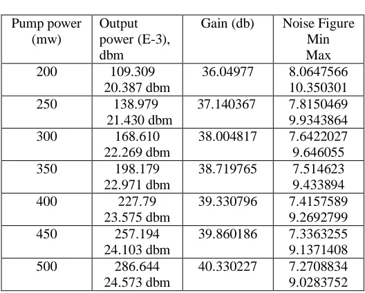
Now at constant optimal length 10m obtained input power, output power, gain ,Max Q factor , Min BER , and Eye
height, noise figure with varying pump power. Input power is same as previous.
Table 3 Pump power (mw) Output power (E-3), dbm
Gain (db) Noise Figure
Min Max
200 109.309
20.387 dbm
36.04977 8.0647566
10.350301
250 138.979
21.430 dbm
37.140367 7.8150469
9.9343864
300 168.610
22.269 dbm
38.004817 7.6422027
9.646055
350 198.179
22.971 dbm
38.719765 7.514623
9.433894
400 227.79
23.575 dbm
39.330796 7.4157589
9.2692799
450 257.194
24.103 dbm
39.860186 7.3363255
9.1371408
500 286.644
24.573 dbm
40.330227 7.2708834
9.0283752
The Max Q factor , Min BER , and Eye height at different pump power are shown in table 4.
Table 4
Pump power (mw)
Max Q Factor
200 2.25595 .00719779 -0.00153939
250 2.38442 .00914903 -0.00216883
300 2.56239 .00512212 -0.00114704
350 2.67910 .00364772 -0.00098357
400 2.82169 .00235695 -0.00064095
450 2.95392 .00386141 -0.00150778
500 2.90417 .00460397 -0.00186093
ACKNOWLEDGEMENT
I would like to thanks to Mr. Sandeep Kumar Yadav Lecturer (E.C.E. Dept.) Govt. Women Engineering College Ajmer for their valuable guidance.
CONCLUSION
The proposed model of EDFA-WDM optical network using GFF has been simulated and studied. As shown in above results when pump power is increasing then output power and gain also increases with it, but noise figure has been decreased with the increased pump power. The Max Q factor also increased continuously with the pump power. It can be concluded that the WDM System integrated with EDFA and GFF gives optimized Q-Factor and Output Peak power, also provide flat gain over a large dynamic gain range, low noise, high saturation output power, and stable operation with excellent transient suppression.
REFERENCES
[1]. Brobrovs.V et al,“EDFA Application Research in WDM Communication Systems”, ELEKTRONIKA IR ELEKTROTECHNIKA , Vol. 19, No. 2, 2013.
[2]. M.N. Zervas, R.L. Laming and D. N. Payne," Efficient EDFA incorporating an optical isolator”, In IEEE journal of quantum electronics, March 1995, vol 31, no.3 UK.
[3]. J.H. Jang, J.H. Jung, K.K.Lee, “Implementation of Automatic gain controlled bidirectional EDFA in WDM Networks” , IEEE CLEO/Pacific Rain 1999.
[4]. N. Zervas, R.L. Laming and David N. Payne," Efficient EDFA incorporating an optical isolator”, In IEEE journal of quantum electrinics, March 1995, vol 31, no.3 UK.
[5]. Aditya Goel and Ravi Shankar Mishra, “Design of broadband EDFA for next generation optical network”, International journal of Neural networks and applications, jan-june 2010, pp.9-13. .
[6]. Masaharu horiguchi, IEEE Journal of Lightwave technology, Vol 12, no.5, May 1994.
[7]. Temmer, H. Ould Saadi and A. Boutaleb, “Simulation based analysis of EDFA, Journal of Applied science, Asian network for scientific information,page no. 789- 794, 2006.
[8]. M.Karasek, “Gain enhancement in gain shifted EDFA for WDM applications”, IEEE photonics technology letters vol 11 no. 9, September 1999.