AN EFFECTIVE QUEUING MODEL BASED
BANDWIDTH ALLOCATION SCHEME FOR FAIR QOS
PROVISIONING IN LTE SYSTEMS
1 M. KARPAGAM, 2N. NAGARAJAN
1
Assistant Professor, Department of ECE, SKCET, Coimbatore, India
2
Principal, CIET, Coimbatore, India
E-mail: [email protected] [email protected]
ABSTRACT
In this paper, we propose a novel bandwidth allocation scheme that will guarantee quality-of-service (QoS) support in the downlink (DL) of a LTE-A system. The proposed scheme is developed based on a queuing model that links important performance metrics of DL service flows of LTE-A systems to a set of tunable parameters. Based on the outcome of the results of the queuing model, the performance metrics are set. The bandwidth allocation scheme then uses the pre-determined performance parameters in making the scheduling decisions. In order to achieve the best results from the proposed scheme, the scheme is integrated with the slot allocation process that is carried out in the physical layer. LTE-A systems uses orthogonal frequency-division multiple access (OFDMA) slot allocation mechanism that adapts to channel conditions at the destination mobile stations (MSs). The proposed scheme performs better than the conventional approach in terms of system throughput, delay and packet dropping ratio, thereby, improving the QoS of the overall system. Further the proposed system is simple in design and its cross-layer approach guarantees improved resource utilization especially in the presence of link adaptations and channel fading. Simulation results have demonstrated that the proposed scheme provides better QoS support for both real-time and non-real-time applications in LTE-A systems.
Keywords:LTE-A, OFDMA, Queuing Model, QoS, Cross Layer Approach.
1. INTRODUCTION
Universal Mobile Telecommunications System (UMTS) Long Term Evolution Release 8 provides high peak data rates of 300 Mb/s on the downlink and 75 Mb/s on the uplink for a 20 MHz bandwidth, and allows flexible bandwidth operation of up to 20 MHz [1]. Currently, enhancements are being studied to provide substantial improvements to LTE Release 8, allowing it to meet or exceed International Mobile Telecommunications-Advanced (IMT-A) requirements [1]. These enhancements are being considered as part of LTE-Advanced (LTE-A, also known as LTE Release 10), which includes carrier aggregation, advanced uplink (UL) and downlink (DL) spatial multiplexing, DL coordinated multipoint (CoMP) transmission [1], [2], [3].
With the growing demand of bandwidth LTE will act as a potential solution to meet the
bandwidth demands of the future. From its onset, the LTE standard comes with a QoS support framework. This is particularly important for LTE systems, as they are expected to support a wide range of multimedia applications, such as voice over IP (VoIP), streaming video, and network gaming, that require certain levels of QoS for their smooth operation. In addition, LTE service providers would also like to offer different levels of QoS support to their clients according to their subscriptions. With LTE, the basic QoS framework remains intact, but new resource allocation issues have emerged with OFDMA at the air interface and for the need to support QoS in the presence of user mobility [4],[5]. One important factor that affects the performance of the LTE system or for that matter performance of any Broadband Wireless Access System is the bandwidth allocation mechanisms.
priority. The algorithm mentioned in [6]
considers multiple service classes of multimedia traffic and their diverse QoS requirements. It contains two parts, a dynamic priority adjustment scheme and a priority-based greedy (PBG) algorithm. The dynamic priority adjustment scheme gives high priority to urgent users and dynamically adjusts the value frame by frame based on users' QoS requirement and queue occupancy [6]. An efficient resource allocation algorithm at physical (PHY) layer, which jointly adapt subcarrier allocation, power distribution and bit loading according to instantaneous channel conditions, is proposed in [7]. The scheduler and the resource allocator are tightly coupled together. A joint transmit scheduling and dynamic sub-carrier and power allocation method is proposed to exploit multi-user diversity in downlink packet transmission in an OFDM wireless network with mixed real-time and non-real-time traffic patterns is proposed in [8]. To balance efficiency and fairness and to satisfy the QoS requirements of real-time users, the algorithm utilizes a utility-based framework and proposes a polynomial-time heuristic algorithm to solve the formulated optimization problem.
The conventional schemes aim to maximize the throughput by using the channel quality information. A change in modulation scheme is effected which will guarantee a specified QoS to the user. Another conventional methodology that exists in the market is based on scheme utility function which will consider the channel status information and QoS and maximize the overall system scheme utility function. [6], [7], [8].
In this paper, we focus on a resource allocation framework that consists of medium access control (MAC) layer packet scheduling and OFDMA resource allocation with the goal of QoS provisioning in LTE systems. We design the framework for DL resource allocation and partial usage of subchannel subchannelization, which is mandatory for all mobile LTE implementations; uplink (UL) resource allocation and optional band adaptive modulation and coding subchannelization are not considered in this paper. The framework is designed to deal with various types of QoS-constrained multimedia and data applications. Due to their dynamic traffic characteristics, the multimedia applications are more challenging to provide QoS. Hence, we aim to provide a framework that is primarily designed for QoS support of multimedia applications but can also be configured with ease to handle other
applications. The QoS framework in LTE systems provides QoS on a per- service-flow basis [9], [10]. The signaling mechanism allows specifying traffic parameters as well as QoS requirements of individual service flows seeking admission into the system. Each admitted service flow is then assigned to a transport connection and is allocated resource inside LTE frames, which consist of a limited number of OFDMA slots. In our proposed resource allocation framework, a joint packet scheduling and OFDMA slot allocation scheme determines how many packets have to be scheduled for each backlogged connection during a frame time and how the available LTE slots need to be allocated to each connection for transmitting those scheduled packets. The objective is to meet QoS guarantees for the admitted service flows, and the constraint is the limited number of OFDMA slots that are available in the LTE frames. How many slots should be allocated in a frame to different connections also depends on the link quality of the destination and the signaling overhead involved in transmitting the allocation information. Therefore, a cross-layer adaptive resource allocation scheme is desirable and pursued.
More specifically, we propose a queuing model based Bandwidth allocation scheme that provides effective resource allocation in Long Term Evolution advanced (LTE-A) downlink systems. The bandwidth allocation scheme effectively computes the traffic model and based on the input derived from the traffic model achieves improved system throughput, reduces the delay, guarantees the QoS and achieves fairness.
intra-class scheduling with the resource allocated
for them in the first layer of scheduling. The hierarchical solutions can significantly increase the implementation complexity of the resource allocation module.
Therefore, the existing solutions might be incompatible and inefficient for LTE-A systems. We, in contrast, design our proposed scheme by offering flexibility to service providers by allowing different probabilistic guarantees to be made for delay experienced by packets belonging to connections serving different customer classes. In addition, the cross-layer design of the resource allocation scheme ensures robustness and efficient resource utilization in the presence of user mobility and channel fading. In addition, compared with some resource allocation schemes (e.g., [6]–[8]) that mainly focus on improving the overall system performance in terms of throughput, transmit power, or fairness in OFDMA-based systems in general, our scheme is focused on meeting QoS guarantees of applications/services in LTE systems.
2. QUEUING MODEL AND ANALYSIS FOR
THE PROPOSED BANDWIDTH
ALLOCATION SCHEME
We first propose a queuing model that will be used in the downlink bandwidth allocation scheme. The queuing model serves a vital factor in determining the set of attributes that will be deployed in the downlink bandwidth allocation scheme. In this section, we describe the scheduling policy and its queuing model that is used to calculate these attributes for admitted service flows. It is worth mentioning that the queuing model proposed and described in this section are not directly adopted in the proposed bandwidth allocation scheme; rather the queuing model is used to determine important attributes or parameters affecting the packet schedulers operation.
At the beginning of every frame the scheduler in the BS computes the total number of packets that were not transmitted in the previous frame and decides to schedule a percentage of the excess packets that were not served in the previous frame to be accommodated in the current frame.
If the queue length of connection i at the beginning of frame n is denoted by qi(n), then the number of packets Ni(n) that will be scheduledfor transmission in the current frame is given by
=
Where L is the maximum limit on the queue size in number of packets, and ki(0<ki<1) is the
transmission parameter associated with connection i.The governing equation governs two factors. First it ensures that it accommodates all the packets that are ready to be served in the current frame. Second, it ensures that each nonempty queue gets to transmit atleast one packet during each frame so that a queue does not remain without service for an extended period of time due to low traffic intensity. The canopy function in this expression is used to convert any fractional values for the number of packets to the nearest integer.
The value of k
i for connection i is based on the
type of service flow and the QoS parameters associated with the service flow. It is now important to formulate the queuing model that would relate the value of k
i with the QoS
performance of connection i given its traffic arrival statistics. If there are m admitted connections that have QoS requirements to fulfill, then the model will enable us to find the values for a set of m such model parameters. Note that if a service flow does not put forward any QoS requirement, then it will be treated as BE traffic. Connections associated with BE traffic will be treated differently than those with QoS traffic and will not need association with a model parameter.
The queuing model proposed in this paper is associated with the downlink resource allocation scheme and it provides strong emphasis on maintaining the QoS of the system. For the sake of easy understating, we simply denoted the model parameter as ‘k’ ignoring the connection identity that is associated with the parameter momentarily without losing the generality of the equation. We assume that the packet arrival process of any service flow associated with the connection and assign the value “k” to it. The main objective of the queuing model is to map the mobility of the downlink queue to a “Finite State Discrete Time Markov Chain (FSDTMC)” and then solve the chain to compute the various performance metrics. The output of the queuing model will be performance metrics which will have values as a function “k” [11], [12].
depending on the current state of a finite-state
Markov chain. The model is preferred by researchers for its high versatility in qualitative behavior. It allows to capture network traffic sources that are bursty in nature. A Markov Modulated Process (MMP) employs an auxiliary Markov process, in which the current state of the Markov process controls the probability distribution of the traffic. MMPP is a variation of a Markov modulated process, where the auxiliary process used is a Poisson distributed process. In other words, MMPP is a doubly stochastic process where the intensity of a Poisson process is defined by the state of a MC. The MC can be visualized to modulate the Poisson process. The MMPP is also identified as a special case of the Markovian Arrival Process (MAP) [13], [14], [15].
MMPPs are classified by the number of states present in the modulating MC. An MC with two states and two different intensities is referred as MMPP-2. It is also called sometimes as a Switched Poisson Process (SPP). An interesting feature to observe in this case, is that when the two intensities are equal, then the model transforms to a typical Poisson process. IPP is a special case of an MMPP, where either of the intensity is zero. Another important aspect of MMPP is that a superposition of MMPPs is also a MMPP. An MMPP with M + 1 number of states can be obtained by superposition of M identical and independent IPP sources [14].
However, in this paper, we limit our analysis to a discrete-time, and therefore, it is convenient to choose a discrete-time equivalent of the MMPP arrival process, and hence we adopt a Finite State Discrete Time Markov Chain (FSDTMC)”. In general, an N-stated-MMPP is described by the transition probability matrix of an N-state Markov chain and a diagonal matrix containing the arrival rates associated with the various states of the Markov chain [13], [14], [15].
In the FSDTMC model the number of arrivals that can happen in a time frame is Poisson
distributed. The transmission rate can however vary from frame to frame based on the state of arrival. As mentioned earlier if the number of arrival process in a particular time frame is Poisson distributed, it means that in theory the value could actually extend to infinity. Let us assume that the maximum number of packets that can arrive in time frame is M. In practice, however, it could be set to some fixed value as the number of packets arriving within a LTE frame will be limited. This is equivalent to truncating the maximum number of Poisson events occurring in one timeslot which could induce some modelling error. The value of M is therefore chosen such that the modelling error is limited to a negligible value (on the order of
10−5 ∼ 10−6). The transition probability matrix that is used to minimize the modeling error is given by
Assuming that matrix S is time independent, the steady-state probability vector is estimated using Grassmann Algorithm [16].
Grassmann’s algorithm is a numerically stable variant of the Gaussian elimination procedure. The algorithm completely avoids subtractions and it is therefore less sensitive to rounding and cancellation errors caused by the subtraction of nearly equal numbers. Grassmann’s algorithm was originally introduced for the analysis of
ergodic, discrete time Markov chains
and was based on arguments from the theory of regenerative processes [17].
The transition rates of a new Markov chain, having one state less than the original one are
defined. This elimination step, i.e., the
computation of is achieved merely by adding
non-negative quantities to originally non-negative
values . Only the diagonal elements
and are negative.
The elimination procedure is iteratively applied
to the generator matrix with entries of
stepwise reduced state spaces until an upper
triangular matrix results, where denotes the
matrix entries after having applied elimination
step . Finally, each element
to express the relations of the state probabilities to each other. To yield the final state probability vector the normalization condition must be applied. Grassmann’s algorithm is presented in terms of a CTMC generator matrix and the parameter matrix must initially be properly defined:
.
In Matrix notation, the parameter matrix A is decomposed into factors of an upper triangular matrix U and a lower triangular matrix L such that the following equations hold 0= xA=xUL.
Of course, any solution of 0=xU is also a solution of the original equation 0=xA. Therefore there is no need to represent L explicitly. Although cancellation errors are being avoided with Grassmann’s algorithm, rounding errors can
still occur, propagate, and accumulate during the composition. Therefore, applicability of the algorithm is also limited to medium size (around 500 states) Markov models.
The analysis of the Markov chain depends on
three given matrices namely the initial
distribution, and the transition matrix P and the finite state sample space given by,
Where
is the number of packets to be serviced.
is the state of the arrival process at the beginning of the frame.
The transition probability matrix P of the FSDTMC may be written as,
The transition matrix is written assuming the existence of the following equations:
1. 1.
Which indicates that an initial distribution = { exists with the associated probabilities for same random variable.
2.
The transition probabilities provide the required probability of transitioning in the space specified from the state.
The transition matrix (4) has the block sub matrices (0 indicating that the transition probabilities associated with the events.
The block sub matrices can be derived as,
..… (8)
for
for
Once the block sub matrices are determined, the steady state probability vector for the Markov chain may be deduced solving for a linear set of equations in terms of the various performance metrics
3. BANDWIDTH ALLOCATION SCHEME
In this section, we may define a number of performance measures from the derived steady state probability vector. The three important performance measures that are estimated in this paper are namely: 1) Delay 2) System Throughput and 3) Packet dropping ratio.
We now estimate the delays that are experienced by the packets in the LTE systems from the steady state probability vector. It is important to use the status report of Buffer Status Report (BSR) in determining the delays experienced by the packets. The BSR reports are generated continuously but are transmitted only when the resources are allocated to the user equipment. If the base station estimates a queue length of bytes at a time but later if finds out that BSR has a value ( bytes, then the base station can deduce that the bytes arrived between time and the time at which the previous buffer status report was generated. The decision on the bytes is made on the scheduling policies and the acceptable packet delays. The major complexity that would arise in estimating the delays is due to the retransmission that would lead to the Buffer Status Report arriving out of order at the Base Station
Let the maximum amount of time between the first transmission of the packet and the latest time when it can be retransmitted to meet the QoS requirements is set to . The number of bytes arrived in a time frame is estimated. The Buffer Status Reports are denoted as
Where the buffer size is reported in the first BSR, is the time at which the first BSR was received and is the time at which the first BSR was generated and so on.
denotes the number of bytes scheduled for transmission and is the number of bytes that failed the retransmission. The probability that i.e, a buffer overflow may occur upon the arrival of a packet may be estimated from
We may temporarily ignore the delay experienced by the retransmitted packets and limit our discussion to delay experienced by only the admitted packets.
At any instant of time the number of scheduled bytes is
The number of bytes that failed is given by
The initial probability vector of the admitted packets may be derived from the Markov chain and buffer status report.
=
The cumulative packet delay of packet frame may be given by
Packet loss happens when there is a buffer overflow. The packet loss rate at the queue is given as
= ……… (16)
However the packets that are lost in the receiving section is not accounted in the above equation. Without considering the retransmitted packets, the average system throughput per time frame may estimated as,
……… ( 17)
where is the average packet error rate.
mentioning that the proposed scheme was able to
achieve significant results as compared to the CSFB at the same time saving significant bandwidth.
4. ALGORITHM
In this section, we explain the proposed fair bandwidth allocation scheme that is based on the above proposed queuing model. The aim of the downlink bandwidth scheduling scheme is to ensure a fair resource allocation to all the users of the network at the same time guarantying the QoS requirements of all the users. Care is taken to ensure that the increased system efficiency is not achieved at the cost of QoS constrained service flows. With the available number of slots that are available in a frame and the QoS requirements of the admitted packs, we aim to perform packet scheduling and OFDMA slot allocation to accommodate enough resources for as many service flows as possible within the frame. Fair resource allocation is achieved by satisfying the QoS guarantee of all admitted service flows.
When a new downlink connection for a particular service value has to be initiated the QoS requirements for the particular service flow is computed and the transmission parameter for the particular service flow is also calculated from the above explained queuing model. The value of ‘ is used to determine the number of backlogged packets in service connection . The value is set between 0 and 1. acts as a multiplying factor. During each iteration, the computed value of from the service model is fed as input to the queuing process along with the Buffer Status Reports. The higher the value means more number of packets are transmitted in the particular frame, which means improved QoS performance. A step wise increment process is followed to increment the size of . The step size though can be defined by the service provider or vendor. The process of iteration continues until the queuing model satisfies the QoS requirements of connection
.
Once the QoS requirements for every connection is satisfied then the scheduler in the base station estimates three namely, the number of packets that are to be transmitted in the current time frame, the number of packets that have failed to be transmitted in the previous frames and BSR report.
On receiving all the status reports the scheduler then decides on the number of packets that are to be scheduled in the current frame. Let be the current frame that is to be serviced. First the
number of active downlink QoS connection are sorted in descending order based on the cost metric . The value for is determined by multiplying the amount of packets that are backlogged with the number of bytes that a single slot can accommodate.
The Scheduler then determine the number of packets that are to be scheduled in the current time frame for each connection. If the connection ’
starts by selecting packets for
connection . Two factors are considered while making the estimation. First, the necessary overhead is added while calculating the number of slots required. Second, the transmission rate that corresponds to the selected frame. If there is enough space left in the frame, then backlog packets are added to it. The next connection in the sorted list is then considered and the preceding process is applied to choose the minimum number of packets and corresponding number of slots.
For every time frame and service connection estimate the transmission parameter . Also estimate the packet arrival statistics, QoS requirement for connection
Transmission parameter is:
1:
2 : Repeat
3 : Increment +
4: Substitute in the queuing model
5: Iterate
6 : Until meets the QoS requirements of connection
7 : Estimate the scheduled bytes, failed bytes and BSR report
8 : Scheduled bytes: (t)= (t-1)- (t)
9 : Failed bytes: (t)= (t)+ (t)
10 : If a BSR report is received at time there is such that (n)=t, then update queue state as follows:
If the base station has not received any BSR report created after time then
Otherwise for argmin
can have negative entries. Schedule packets, allocate slots for the current time frame
.
11: number of slots in the downlink frame.
12: estimate the number of slots for downlink QoS connections.
13: for do
14: Initialize the slots allocated for each QoS connection to
15: ; slot identifier
16: number of bytes allotted for each slot
17: * number of backlog bytes at each connection
18: end for
19: Sort the QoS connections based on the values of
20: Allocate the slots to the connection
21: Repeat
22: list of scheduled connections
23: for 1……….. m do
24: Number of packets selected based on queue
length and transmission parameter ;
25: number of bytes in top packets in the queue
26: Estimate the number of slots necessary to transmit packets over connection
27: if then
28: end if
29: If then
30:
31: if then
32:
33: end if
34: queue length updated
35: end if
36: end for
37: until (:
5. SIMULATION RESULTS:
5.1 Simulation Scenario:
In the simulation analysis, OPNET is used for simulation and the results were exported to MATLAB Simulator. The LTE-A system is set to be compatible to the 3GPP evolved universal terrestrial radio access standard [18] with Q = 2,N = 25, and PT = 43 dBm, where the cell radius is 1 km, the carrier frequency is 2 GHz, and the system bandwidth is 5 MHz. The path loss is modeled as 136.82 + 39.09logR dB, where R is the distance between the eNB and the UE [19]. The multipath channel for each antenna has six taps of Rayleigh- faded paths with an exponential power delay. The log-normal shadowing has zero mean and standard deviation of 8 dB. The penetration loss was set to 20 dB. The thermal noise was chosen to be -100 dBm. SISO antenna configuration is used with the Channel Quality Index Feedback cycle estimated at every 10 ms.
5.2 Performance Evaluation
In this paper, the proposed Effective Bandwidth Admission Scheme (EBAS) is compared to the adaptive radio resource allocation (ARRA) scheme [6], the efficient resource management scheme (ERMS) [7], and the utility-based adaptive radio resource allocation (UARRA) scheme [8].
Figure 1 depicts the system throughput versus traffic load intensity for the proposed scheme with the various schemes. The proposed EBAS scheme was able to achieve an improved system throughput by 18.9 %, 37.5%, and 56% compared to the UARRA, ERMS and ARRA schemes, respectively, under heavy traffic conditions. This is because the proposed scheme intelligently assigns the bandwidth based on the proposed queuing model. Priorities are based on actual statistics rather than the fuzzy statistics that are adapted in the other schemes. Also, the EBAS scheme uses the cross layer adaptation technique wherein the sub channels are allocated based on the demand. This would ensure minimization of wastage of resources and maximization of the system throughput. This makes the EBAS scheme more effective than the other schemes.
guarantees that the proposed scheme has achieved
the increased system throughput not by compromising the QoS of voice.
0 0.1 0.2 0.3 0.4 0.5 0.6 0.7 0.8 0.9 1 0 5 10 15 20 25 30 35 40 45
TRAFFIC LOAD INTENSITY
[image:9.595.88.516.81.524.2]S Y S T E M T H R O U G H P U T (M b p s ) SYSTEM THROUGHPUT ARRA ERMS UARRA EBAS
Figure 1: System Throughput
0 0.1 0.2 0.3 0.4 0.5 0.6 0.7 0.8 0.9 1 0 0.2 0.4 0.6 0.8 1 1.2 1.4
TRAFFIC LOAD INTENSITY
P A C K E T D R O P P IN G R A T IO (% )
PACKET DROPPING RATIO-VOICE TRAFFIC
ARRA ERMS UARRA EBAS
Figure 2: Packet Dropping ratio for Voice
The ARRA, ERMS and UARRA, and ERM schemes cannot guarantee the QoS requirement of packet dropping ratio for video traffic when the traffic load intensity is larger than 0.35, 0.85 respectively as illustrated in Figure [3]. However the proposed scheme is also able to maintain the QoS for video packets also. This is because the other schemes allow the downlink station to choose packets with larger delay time to be served with higher priority whenever it serves rate sensitive services. This will only result in lot of resources being wasted. However, as the proposed scheme does not provide priority to rate sensitive traffic and thus ensures delivery of packets with acceptable QoS.
0 0.1 0.2 0.3 0.4 0.5 0.6 0.7 0.8 0.9 1 0 0.5 1 1.5 2 2.5 3 3.5 4 4.5
TRAFFIC LOAD INTENSITY
P A C K E T D R O P P IN G R A T IO (% )
PACKET DROPPING RATIO-VIDEO TRAFFIC
[image:9.595.97.289.136.522.2]ARRA ERMS UARRA EBAS
Figure 3:Packet Dropping Ratio for Video
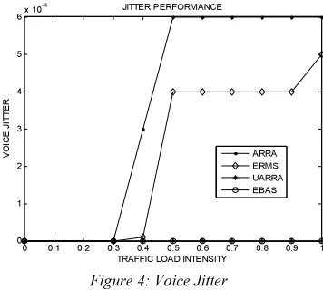
Voice jitter is another important parameter in estimating the QoS of voice packets. Figure 4 clearly illustrates that the ARRA scheme and the ERMS definitely experience jitter in higher traffic conditions. However, the proposed EBAS and UARRA scheme do not experience voice jitter even under heavy load conditions. This is because the proposed scheme computes the required resources based on queuing model prior to the allocation of resources to the various channels. This ensures that there is a steady availability of resources during the scheduling scheme thereby guarantying QoS demands.
0 0.1 0.2 0.3 0.4 0.5 0.6 0.7 0.8 0.9 1
0 1 2 3 4 5 6x 10
-4
TRAFFIC LOAD INTENSITY
VO IC E J IT T ER JITTER PERFORMANCE ARRA ERMS UARRA EBAS
Figure 4: Voice Jitter
[image:9.595.319.497.473.633.2]time multimedia applications which deprives the
non-real time traffic of resources. However the proposed scheme still works better than the UARRA.
0 0.1 0.2 0.3 0.4 0.5 0.6 0.7 0.8 0.9 1 0
0.1 0.2 0.3 0.4 0.5 0.6 0.7 0.8 0.9
TRAFFIC LOAD INTENSITY
J
A
IN
F
A
IR
N
E
S
S
I
N
D
E
X
FAIRNESS INDEX
ARRA ERMS UARRA EBAS
Figure 5: Fairness Index
6. CONCLUSION
In this paper, a novel bandwidth allocation scheme for DL service flows in LTE-A systems is proposed. At first, we have proposed a queuing model and we have used the parameters of the model to develop the bandwidth allocation scheme. The scheme is the coupled with the OFDMA slot allocation process to achieve best results. Simulation results have demonstrated that the proposed scheme outperforms the existing schemes for both real and non-real time applications. However, it would be interesting to study the compatibility and performance of the proposed scheme in a real time hardware LTE system.
REFERENCES
[1] 3GPP TR 36.913, “Requirements for Further Advance- ments for Evolved Universal Terrestrial Radio Access (E- UTRA),” v. 8.0.1, Mar. 2009; ftp://ftp.3gpp.org
[2] A. D. Dabbagh, R. Ratasuk, and A. Ghosh, “On UMTS- LTE Physical Uplink Shared and Control Channels,” IEEE 68th VTC, Sept. [3] ITU –R Rep M.2134, “Requirements Related
to technical Performance for IMT – Advanced Radio Interface(s),” 2008
[4] Haiyan Luo; Song Ci; Dalei Wu; Jianjun Wu; Hui Tang, "Quality-driven cross-layer optimized video delivery over LTE," Communication Magazine, IEEE , vol.48, no.2, pp. 102,109, February 2010.
[5] Srikanth, S.; Murugesa Pandian, P.A.; Fernando, X., "Orthogonal frequency division
multiple access in WiMAX and LTE: a comparison," Communications Magazine, IEEE , vol.50, no.9, pp.153,161, September 2012
. [6] C. F. Tsai, C. J. Chang, F. C. Ren, and C. M. Yen, “Adaptive radio resource allocation for downlink OFDMA/SDMA systems with multimedia traffic,” IEEE Trans. Wireless Commun., vol. 7, no. 5, pp. 1734–1743, May 2008.
[7] H. Xu, H. Tian, Y. Feng, Y. Gao, and P. Zhang, “An efficient resource management
scheme with guaranteed QoS of
heterogeneous services in MIMO-OFDM system,” in Proc. 2008 IEEE WCNC, pp. 1838–1843.
[8] M. Katoozian, K. Navaie, and H. Yanikomeroglu, “Utility-based adaptive radio resource allocation in OFDM wireless networks with traffic prioritization,” IEEE Trans. Wireless Commun., vol. 8, no. 1, pp. 66–71, Jan. 2009.
[9] C. M. Yen, C. J. Chang, and L. C. Wang, “A utility-based TMCR scheduling scheme for downlink MIMO/OFDMA systems,” IEEE Trans. Veh. Technol., vol. 59, no. 8, pp. 4105–4115, Oct. 2010.
[10] Peng, S. M. D. Armour, and J. P. McGeehan, “An investigation of dynamic subcarrier allocation in MIMO-OFDMA systems,” IEEE Trans. Veh. Technol., vol. 56, no. 5, pp. 2990–3005, Sep. 2007.
[11] Aiguo Xie; Beerel, P.A., "Efficient state classification of finite-state Markov chains," Computer-Aided Design of Integrated Circuits and Systems, IEEE Transactions on , vol.17, no.12, pp.1334,1339, Dec 1998.
[12] Krishnamurthy, V., "How to Schedule Measurements of a Noisy Markov Chain in Decision Making?" Information Theory, IEEE Transactions on , vol.59, no.7, pp.4440,4461, July 2013.
[13] H. Kobayashi and B. L. Mark, System Modeling and Analysis: Foundations of System Performance Evaluation. Englewood Cliffs, NJ: Prentice-Hall, 2008.
[14] P. Salvador, A. Pacheco, and R. Valadas, “Multiscale fitting procedure using Markov modulated Poisson processes,” Telecommun. Syst., vol. 23, no. 1/2, pp. 123–148, Jun. 2003. [15] D. P. Heyman and D. Lucantoni, “Modeling
IEEE/ACM Trans. Netw., vol. 11, no. 6, pp.
948– 958, Dec. 2003.
[16] Dimitar Radev, Vladmir Denchev, Elenka Rashkova, “Steady State Solution of Markov Chains”, 7th Balkan Conference on Operation Reasearch”, BACOR ’05, May 2005.
[17] Bolch, G., Greiner, S., Meer, H, Trivedi, K., “Queueing Networks and Markov Chains: Modelling and Performance Evaluation with Computer Science Applications”, New York, John Wiley & Sons, 726pp.
[18] 3GPP TR25.814, “Physical layer aspects for evolved UTRA,” 3GPP Tech. Rep., 2005. [19] 3GPP TR 25.892, “Feasibility study for
OFDM for UTRAN enhancement,” 3GPP Tech. Rep., June 2004.