DOS-IS
SYSTE~1
MAN UAL
DEC-lS-ODFFA-A-D
FOR ADDITIONAL COPIES OF THIS MANUAL
JORDER THE NUMBER ABOVE FROM THE
PROGRAM LIBRARY
JDIGITAL EQUIPMENT CORPORATION
JMAYNARD
JMASSACHUSETTS
First Printing, January 1972
Second Printing, July 1972
Copyright
(S)
1972 by Digital Equipment CorporationThe material in this document is for informa-tion purposes and is subject to change without notice.
The following are trademarks of Digital Equipment Corporation, Maynard, Massachusetts:
COP
Computer Lab Comtex
DEC OECtape Dibol
Digital DNC
Flip Chip IOAC Indac KAlO
LAB-8/e OMNIBUS OS/8 PDP
PHA
PS/8
Quickpoint
PREFACE
CHAPTER 1
CHAPTER 2
2.1 2.2 2.3 2.3.1 2.3.2 2-4 2-5 2.6 2.6.1 2.6.2 2.7 2.8
CHAPTER 3
3.1
3.2
3.3
3.4
CHAPTER 4
4.1 4.2 4.4 4.5 4.6 CON~ENTS
DOS OPERATION
THE RESIDENT MONITO~
INTRODUCTION
THE CAL HANDLER
I
2-1
2-2
lOPS ERROR HANDLER, AND THE EXPANDED ERROR PROCESSOR 2-2
.MED I 2-2
The Expanded Error ~rocessor 2-6
THE SYSTEM BOOTST~
SYSTEM I/O INITIALIZATION
RESIDENT MONITOR TIMING FEATURES
Clock Operation
.TIMER
THE RESIDENT MONITOR PATCH AREA
CONTROL CHARACTERS
THE NONRESIDENT MONITOR
INTRODUCTION
COMMANDS TO THE NONRESIDENT MONITOR
CONSIDERATIONS FOR ADDITIONS TO THE NONRESIDENT MONITOR
QFILE
THE SYSTEM LOADER AND THE LINKING LOADER
MANUAL BOOTSTRAP LO~DS AND RESTARTS
I
LOADING SYSTEM PROG~S
I
TABLES AND INFORMATION BLOCKS USED AND BUILT
I
BY LOADERS
I
.DAT SLOT MANIPULATION BY THE SYSTEM LOADER
BUFFER ALLOCATION BY THE SYSTEM LOADER
CHAPTER
5
5.1 5.2 5.2.1 5.2.2 5.2.3 5.3 5.4 5.4.1 5.4.2 5.4.3 5.4.4 5.4.5 5.4.6 5.5 5.5.1 5.5.2 5.5.3 5.6 5.7CHAPTER 6
6.1 6.1.1 6.1.2 6.2 6.2.1 6.2.2 6.2.2.1 6.2.2.2 6.2.2.3 6.2.3 6.2.4 6.3 6.3.1 6.3.2 6.3.3 6.3.4 6.3.4.1 6.3.4.2 6.3.5 6.3.6 6.3.7
SYSTEM INFORMATION BLOCKS AND TABLES II
I
CORE-RESIDENT NON-REFRESHED REGISTERS
I
DISK-RESIDENT UNCHANGING BLOCKS SYSBLK
COMBLK SGNBLK
I
DISK-RESIDENT CHANGING BLOCKS
I
TEMPORARY TABLES BUILT FROM DISK-RESIDENT TABLES
The Overlay Table The Device Table
The Input/Output Communication (IOC) Table The Device Assignment Table (.DAT)
The User File Directory Table (.UFDT) The Skip Chain
TEMPORARY TABLES BUILT FROM SCRATCH File Buffer Transfer Vector Table The RCOM Table
The Mass Storage Busy Table
I RESERVED WORD LOCATIONS
II
BOOTSTRAP NON-BOSS BATCH BITS
I
FILE STRUCTURES
DECTAPE FILE ORGANIZATION Non-Directoried DECtape Directoried DECtape
MAGNETIC TAPE
Non-directoried Data Recording (MTF) Directoried Data Recording (MTA., MTC.) Magnetic Tape File Directory
User-File Labels File-Names in Labels Continuous Operation
Storage Retrieval on File-Structured Magnetic Tape
DISK FILE STRUCTURE . Introduction
User Identification Codes (UIC)
Organization of Specific Files on Disk Buffers
Commands that Obtain and/or Return BuffE~rs
The Current Set Pre-allocation
Storage Allocation Tables (SAT's) Bad Allocation Tables (BAT's)
CHAPTER 7 7.1 7.1.1 7.2 7.2.1 7.2.2 7.3 7.3.1 7.3.2 7.3.3
CHAPTER 8
8.1 B.l.l B.l.2 B.l.3 B.2 8.3
APPENDIX A
APPENDIX B
APPENDIX C
WRITING NEW I/O DEVICE HANDLERS
I/O DEVICE HANDLERS, AN INTRODUCTION Setting Up the Skip Chain and API
(Hardware) Channel Registers Handling the Interrupt
API SOFTWARE HANDLERS, An Introduction Setting Up API Software Channel Registers Queueing
WRITING SPECIAL I/O DEVICE HANDLERS
Discussion of Example A by Parts
Example A, Skeleton I/O Device Handler Example B. Special Device Handler for AFOIB A/D Converter
BOSS-IS
PROCEDURE FILES
Procedure File Format Direct Substitution
Example of Procedure File
BOSS-15 ACCOUNTING
B.PRE
DECtape 'A' Handler (DTA.)
Disk "A" Handlers
PROCEDURE FILES
This manual was written for customer ~ystems programmers, DEC Software I
Specialists, and internal maintenance programmers. Readers must be
I
familiar with the DOS User's Manual, DEC-15-MRDA-D. In addition,
chap-I
CHAPTER 1
DOS OPERATION
The System Manager must use DOSSAV in order to load DOS-IS for the
first time. The DOS System Generator manual, DEC-15-YWZB-DN12,
des-cribes DOSSAV operation in its appendix. After successful DOSSAV
op-eration, the System Manager should load the Bootstrap into the highest
bank. (This tells DOS how many banks i t can use.) The Bootstrap loads
the System Loader, which in turn loads the Nonresident Monitor. In
order to ensure a working system, the System Manager should place the
DOS-IS Checkout Package tape (RF.CHK, DEC-lS-CIDA-PA, for RF DECdisk
systems, or RP.CHK, DEC-lS-CTAA-PA, for RP~2 Disk Pack systems) into
the Paper Tape Reader, and type BATCH PR~. Operating instructions
for the Checkout Package, and the tape itself, are distributed as part
of the DOS-IS system.
Once the system has been checked out, the System Manager should use
DOSGEN, the DOS System Generator orogram, to tailor the system to
his needs. As mentioned in the System Generator manual, a complete
tailoring of the system may also involve use of PATCH, PIP, and
UPDATE.
Commands to the Nonresident Monitor allow temporary modification of
the system, in order to suit the needs of a particular program. The
Nonresident Monitor modifies the system by changing information in
the .SCOM Table. The System Loader examines the .SCOM Table, along
with three disk-resident information blocks, SYSBLK, COMBLK and SGNBLK,
and carries out all operations necessary to fulfill the operator's
commands. The System Loader "builds" the Resident Monitor by
relocat-ing and linkrelocat-ing those routines indicated by the .SCOM table as needed
by the next core load. The Resident Monitor then retains general
con-trol over the system.
CHAPTER 2
THE RESIDENT '10NITOR
. 2.1 INTRODUCTION
The Resident Monitor gets its name because i t seems resident to the user.
Strictly speaking, however, the only part of the system that is always
resident is the Bootstrap. There are two parts of the system that are
refreshed only after manual Bootstrap lo&ds and restarts: .SCOM and the
Resident :-1onitor Patch Area. Every time an operator or program changes
certain key system parameters, the system will build a new Resident
Monitor from blocks stored on the system device.
The Resident Monitor is the interface between the operator, and the
active devices on one hand, and the program which is running (the
Nonresident Monitor), on the other. The Resident Monitor always contains
the following routines and tables:
Chapter
S
This Chapter
( .DAT .UFDT .SCOM
The CAL Handler, which routes all System and I/O Macro calls
The Startup routine after usinq the Bootstrap .MED, the Monitor's standard error routine
The Expanded Error Processor, for more flexibility with error messages
Handlers for the following error conditions: Nonexistent Memory
Memory Protect
Interrupt-Memory Parity Power-Fail
Software API not set up
The Monitor's TRAN routine (different from I/O .TRAN's) A clock handler
The .GTBUF and GVBUF processor
The CTRL Q processor
The .USER processor The .OVRLA processor TTA.
The Resident Monitor's Patch A
1
eaIn addition, the user can request the system to retain certain other
routines in a resident Monitor status:
The CTRL X Feature, including a driver for the VT-IS
The paper Tape or Card Reader Handler for Batch
The Resident Batch code
BOSS-IS also has resident routines, wnich are covered in Chanter 8.
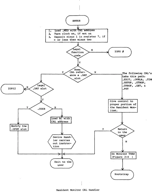
2.2 THE CAL HANDLER
The CAL instruction transfers control to re~ister 21, bank ~, and loads register 251 with the address of the next instruction after t:he CAL.
I
All DOS I/O and system macros take the form of a CAL instruction
(pos-I
sibly with some code in the low-order bits), and the next sequential
register contains a dispatch code. Some mabros require more
informa-I
tion in succeeding registers. Figure 2-1, Resident Monitor CAL Handler,
I
illustrates the operation of that portion of the Resident Monitor. The
I
CAL Handler does only minimal error checkin
r --
for legal function code, and for legal .DAT slot. Aside from that, and ensuring theI
clock is turned on, the CAL Handler is only a dispatcher to other
I
routines.
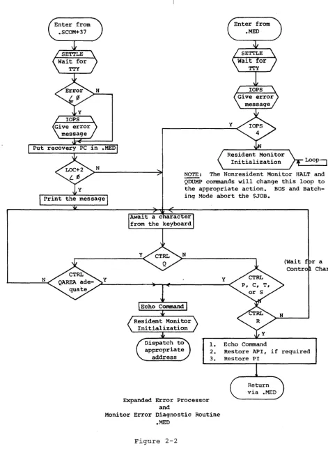
2.3 lOPS ERROR HANDLER, AND THE EXPANDED ERROR PROCESSOR
I
2.3.1
.MED
There are two error processors in the Resident Monitor: .MED and the
!
Expanded Error Processor. Figure 2-2 illustrates those routines.
!
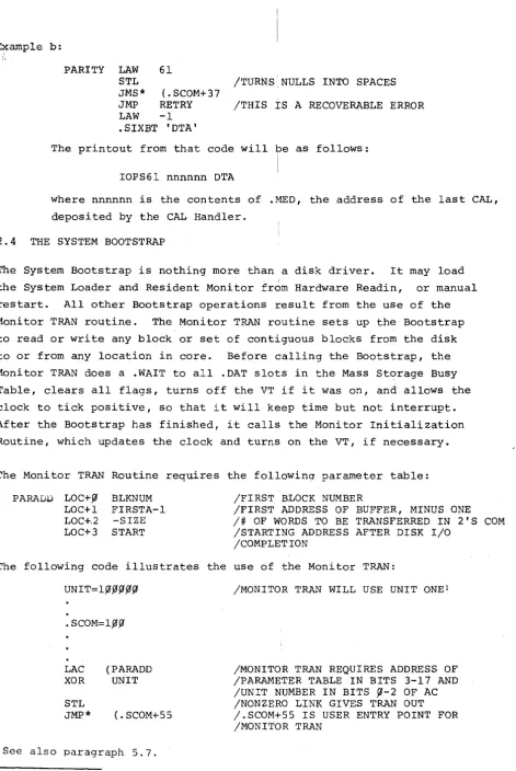
Figure 2-3 shows two subroutines used by th7 error routines. .MED
I
(location 3, bank ~) processes lOPS errors from all device handlers
I
except the disk handlers, and COB., MTF., TTA., and LPA. Calls to
I
.MED should take the following form, if not lOPS 4:
I
LAC INFO /ARGUMENT OF ERROR
DAC* (. MED /ADDRESS OF CAL IS ALREADY IN . MED, /IF DESIRED
LAW N
IN
IS ERROR CODE ~~N~777. AC MUST BE NEGATIVE. JMP* (. MED+IlOPS 4 messages may take the following form:
LAC (4 JMS* (.MED
lAC MUST BE POSITIVE
.MED+I contains a JMP to the Monitor Error Diagnostic Routine. The
I
above calls to .MED will cause the follOwin? printouts:
IOPSN (contents of .MED) IOPS4
IOPS2
Loa ress
2. Turn clock on, if on
3. Deposit minus 1 in register 7, if
= or less than minus two
N
lOPS ~
y ~_N
________________ ~The following CAL's
y
Resident Monitor CAL Handler
Figure 2-1
take this path: .EXIT, .OVRLA, .TlMER • SETUP, • GTBUF ,
.GVBUF, .GET, &
• PUT
[image:11.621.60.572.29.682.2]Enter from .SCOM+37
y
Enter from .MED
Put recovery PC 1n .MED
N y
Initialization
NOTE: The Nonresident Monitor HALT and
QDUMP commands will change this loop to
the appropriate action. BOS and
Batch-ing Mode abort the $JOB.
Expanded Error Processor and
y
1. Echo Command
(Wait f r a Contro Char)
2. Restore API, if required
3. Restore PI
Return via .MED
Monitor Error Diagnostic Routine .MED
Figure 2-2
[image:12.617.79.550.56.706.2]SETTLE
1. Store error number
2. Set up to turn nulls into
spaces, if LINK is set
3. Turn off PI
4. wait 110 ms for the teleprinter to die down
5. Type Carriage RBTURN, Line Feed
Print "IOPS" and error number, zero suppressed
Print a space, fol~owed by the
octal contents of .MED, followed by another space
N
Print contents of .SCOM+32 (disk block number)
Resident Monitor Subroutines
Figure 2-3
[image:13.612.208.481.34.688.2]2.3.2 The Expanded Error Processor
The disk handlers (except the Bootstrap), CDB., MTF., TTA., and LPA.
use the Expanded Error Processor. Each error message is "potentially"
I
recoverable by typing CTRL R. That is, the Resident Monitor always
returns control to the caller upon a CTRL R. It is up to the caller
to respond accordingly. All handlers supplied with the system simply
repeat the error message if the error is unrecoverable. I
The Expanded Error Processor gives the capability of printing
addi-tional information after the standard lOPS message. As with .MED, the
AC must contain the error number (~<number<777)
-
in bits 9-17. Control-
.must be passed, however, via JMS* (.SCOM+37, not JMP* (.MED+l.
The following information pertains to the message: LOC+2 must contain
the two's complement of the number of message words to be typed after
the standard "IOPSNN nnnnnn" message. If the number is zero or
posi-tive, no message will be printed. If the LINK is set, nulls will be
printed as spaces. If the LINK is zero, nulls will be ignored. If
the AC is positive on calling the expanded error facility, only the
special message will be printed. The "lOPS" part will be omitted.
The message itself must be packed in .SIXBT.
The following are examples of use of the Expanded Error Processor:
Example a:
UNREC LAC STATUS
DAC* (.MED
STL
LAW ERRNUM
JMS* (. SCOM+37
JMP UNREC
LAW -1
.SIXBT IDKAI
UNITNO
fI
.SIXBT IFILl .SIXBT IE' .SIXBT 'SRC I
/STATUS
/CAL ADDRESS IS NOW OVERWRITTEN /BY CONTENTS OF STATUS REGISTER /TURN NULLS INTO SPACES
~ERRNUM <l~~ ~
/THIS IS AN UNRECOVERABLE ERROR. /JMP .-1 WILL NOT DO -- EXPANDED /ERROR PROCESSOR CHANGES THE /CONTENTS OF .MED.
The printout from that code will be as follows:
IOPS777 nnnnnn DKA FILE SRC
where nnnnnn is the contents of .MED, and equals the Status Register
B, and ERRNUM was 777.
PARITY LAW 61
STL /TURNS NULLS INTO SPACES
JMS* (.SCOM+37
JMP RETRY /THIS IS A RECOVERABLE ERROR
LAW -1
.SIXBT 'DTA'
The printout from that code will be as follows:
IOPS61 nnnnnn DTA
where nnnnnn is the contents of .MED, the address of the last CAL,
deposited by the CAL Handler.
2.4 THE SYSTEM BOOTSTRAP
The System Bootstrap is nothing more than a disk driver. It may load
the System Loader and Resident Monitor from Hardware Readin, or manual
restart. All other Bootstrap operations result from the use of the
Monitor TRAN routine. The Monitor TRAN routine sets up the Bootstrap
to read or write any block or set of contiguous blocks from the disk
to or from any location in core. Before calling the Bootstrap, the
Monitor TRAN does a .WAIT to all .DAT slots in the Mass Storage Busy
Table, clears all flags, turns off the VT if i t was on, and allows the
clock to tick positive, so that i t will keep time but not interrupt.
After the Bootstrap has finished, i t calls the Monitor Initialization
Routine, which updates the clock and turns on the VT, if necessary.
The Monitor TRAN Routine requires the followinq parameter table:
P ARADU LOC+ fJ LOC+l LOC+.2 LOC+3
BLKNUM FIRSTA-I
-SIZE START
/FIRST BLOCK NUMBER
/FIRST ADDRESS OF BUFFER, MINUS ONE
/# OF WORDS TO BE TRANSFERRED IN 2'S COM
/STARTING ADDRESS AFTER DISK I/O /COMPLETION
The following code illustrates the use of the Monitor TRAN:
UNIT=lfJ~fJfJfJ
.SCOM=l~fJ
LAC (PARADD
XOR UNIT
STL
JMP* (. SCOM+55
See also paragraph 5.7.
/MONITOR TRAN WILL USE UNIT ONEl
/MONITOR TRAN REQUIRES ADDRESS OF /PARAMETER TABLE IN BITS 3-17 AND
/UNIT NUMBER IN BITS ~-2 OF AC
/NONZERO LINK GIVES TRAN OUT /.SCOM+55 IS USER ENTRY POINT FOR /MONITOR TRAN
[image:15.617.77.548.24.728.2]I
.OVRLA, .EXIT,
and manual Q dumps all use the MonitorTRAN
routine.I
Figure 2-4, .OVRLA, .EXIT and CTRL Q, illustrates their operation,
i
and also the Monitor TRAN.
For the RF DECdisk, the user can reference, a specific platter just by
I
identifying the block number he wants. That is, the block numbers to
I
not automatically go to zero at the beginning of every platter. The
I
block numbers and platter relationships are shown below:
I
2.5
TABLE 2-1
RF Platter-Block Number Correspondence
I
Platter Number
~ 1 2 3 4 5 6 7
(All numbers
SYSTEM I/O INITIALIZATION
Block Number
~-1777 2~{i1j1-3777 4{i1j1{i1-S777 6j1{i1j1-7777 l{i1j1{i1.0-1l777 l2~.0{i1-l3777 l4j1~.0-1S777 l6{i1j1{i1-l7777
are in
I
i I
I
octal)
There are two routines that do DOS I/O initialization: the startup routine
1
after Bootstrap manual loads and restarts, and the startup routine
I
performed after Monitor TRAN's and after a CTRL C, P, T or S for an
I
error. The startup routine after Bootstrap loads is described in
. -_ . -- - - I
Figure 4-1, The System Loader Interface Routine. Figure 2-5, Resident
1
Monitor Initialization, describes the other routine.
I
2.6 RESIDENT MONITOR TIMING FEATURES
I
Figure 2-6, The Resident Monitor Clock Routine, describes the Resident
i
Monitor'S time functions. There are three places in DOS which start or try to update the clock -- (1) the first-time initialization after
i
manual Bootstrap loads and restarts, (2) the Resident Monitor
Initial-'I
ization, and (3) the CAL Handler. The following .SCOM registers
con-I
tain timing information:
Y
.OVP..LA
CAL Entry
Put System pro-gram name into .SCOM+43,44 (pro name pointed to by CAL+2)
Scan Overlay Table (address in .SCOM+31) for a match with the
N
.EXIT CAL Entry
Put name of the Nonresident Mon itor into .SCOM
43 & 44
Set up pointer to TRAN parameters
Set up unit number ~ and
pointer to TRAN parame-ters for loading .SYSLD Clear LINK for .TRAN in
Update .SCOM+31 clear AC and the
LINK (Unit ~, & ~--~
Entry
Set LINK (.TRAN out) and set up pointer to .TRAN parameters for CTRL QAREA
Put contents of .SCOM+72 into .SCOM+7l, and set AC with unit number
.TRAN in) (MONITOR TRAN ROUTINE -- Independent from
device handler .TRAN's)
Return to user
Store Unit number and other TRAN parameters in the Bootstrap
Put starting address into
location ~, bank ~, and
set the Bootstrap to go to Monitor Recovery Routine on exit
Bootstrap
I
.OVRLA, .EXIT and CTRL Q
I . . Figure 2-4
I
2-9
*
CLEAR does a .WAIT or a.INIT to each entry in the Mass Storage Busy
Table. This precludes
conflicts between disk I/O performed by the system disk handler, and disk lOT's issued by the Bootstrap, an independent
program. CLEAR also turns
Entry from Bootstrap
Entry from RESMON
set exit to address in ~ Arrive with exit address in AC
1.
2. 3. 4.
5.
Set up clock so that it keeps running, but does not interrupt (ticks positive)
Clear all flags Turn off PI and API
Restore cell 4 to transfer to Error Diagnostic Routine Set up proper addressing
(Bank or Page), according to .SCOM+4, bit 7
1. Update the clock, and allow it to
interrupt
2. Clear TTY Busy Switch (Clear all
flags ensures no I/O to TTY)
3. Turn API on or off, depending on
contents of register 6 (The
Sys-tem Loader loads register 6
ac-cording to .SCOM+4, bit ~)
4. Turn on PI
proper location
Resident Monitor Initialization
Figure 2-5
Ent.rY frolll PI or API
Allow clock to tick positive, so it will not interrupt for an hour
set up the exit from this routine to go to the .TIMER address in .SCOM+61, is if it were a JMS in-struction. Set high-order bits of return address with interrupt information
.SCOM+50 hhmmss Increment .SCOM+34
Subtract one from
N
Restore pre-interrupt conditions
I
Note: The Clock Routine will use PI if API i~ busy, or down.
I
The Resident Monitor Clock Routine
• I
Fl..gure 2-6
.SCOM+5~ .SCOM+51 .SCOM+56 .SCOM+6~ .SCOM+6l .SCOM+73 .SCOM+74
2.6.1 Clock Operation
Time of day, in hhmmss (six bits each) Elapsed time, in ticks
Time limit, in seconds (zero, if no limit) Time left for .TIMER interrupt (zero, if
.TIMER not in effect)
Address of .TIMER
user interrupt routine
Number of ticks left in the next second Line frequency, in ticks per second
The Nonresident Monitor's TIME command changes or senses .SCOM+5~ •
. SCOM+51 is not used by any system program. The clock handler simply
increments i t upon each clock tick. User programs may deposit a known
I
quantity into .SCOM+51, in order to time events. The Nonresident
I
Monitor deposits the argument for a TIMEST command into .SCOM+56. If
i
.SCOM+56 is nonzero, the Resident Monitor will issue an ISZ .SCOM+56 I
command each second, until i t reaches zero. At such a time, the
Resi-I
dent Monitor will perform a .EXIT. MICLOG, LOGIN, and LOGOUT clear
I .SCOM+56.
I
2 • 6 • 2 . TIME R
.TIMER
allows users to schedule routines for a specified time from"now". These routines may return to the interrupted code, if the
I
programmer desires. .TIMER users should take care that the
time-I dependent code follows certain rules:
a. When a programmer does not wish to reset the .TIMER
mechan-ism, but wishes to return to the interrupted program, his code should look like this:
C
DAC
LAC RAL LAC
XIT JMP*
~
SAVEAC
C
SAVEAC C
/C+l REACHED VIA JMS
/MUST NOT USE NON-REENTRANT CODE /POSSIBLY USED BY THE INTERRUPTED
/PROGRAM. (INCLUDES THE CAL
IN-/STRUCTION)
/RESTORE THE LINK
/RESTORE THE AC
h.
When the programmer does wish to reset the .TIMER mechanism, and return to the interrupted code, his routine should look like this:C
.SCOM=I,0~ CLON=7,0~~44 CLOF=7~fJ~fJ4
INTRVL=-lfJ~
DAC
LAC DAC* CLOF
LAC DAC* LAC RAL LAC CLON
fJ SAVEAC
ADDRES ( .SCOM+61
INTRVL (. SCOM+6fJ
C
SAVEAC
JMP* C
/THIS ROUTINE WILL RUN EVERY 1,0~8+
/TICKS
/RETURN TO THE NEXT ROUTINE
/TURN THE CLOCK OFF TO ENSURE NO /REENTRANCE BEFORE .TlMER RESET AND /RETURN
/DESIRED INTERVAL IN TWO'S COMPLEMENT
/RESTORE THE LINK
/RESTORE THE AC
/TURN THE CLOCK BACK ON (AFTER NEXT /INSTRUCTION)
c. When a programmer does not wish to return to the interrupted
program, he need not save the AC, and he may use the CAL
in-struction. He should beware of using I/O buffers that may
still be modified by a handler's interrupt section. In many
cases, a .INIT to an active .DAT slot will terminate I/O. Teleprinter I/O should be terminated by the following:
XCT* (.SCOM+35
The user should program a delay of at least llfJ milliseconds after such an instruction, before he attempts teleprinter I/O.
Note: The interrupt routine will run at the level of the
in-terrupted code, with the same addressing mode and memory
pro-tect status. Thus, no debreak and restore is required.
2.7 THE RESIDENT MONITOR PATCH AREA
There are two types of patch area taken from the space allocated at
assembly time:
1. That allocated by using PATCH
2. That allocated when answering the Patch Area
question in system generation
Patch area one is the place for permanent changes to the Resident
Monitor. It is always refreshed when the System Loader comes into
core. Patch area two is only refreshed on manual Bootstrap loads
and restarts. The second area would be appropriate for communication
between successive programs loaded by the System Loader. This area
should be used because the System Loader refreshes all of core,
ex-cept the Bootstrap, .SCOM, the CTRL X buffer, and the patch area two.
The combined size is limited by the current assembly at 47~~8. Both
areas can be initialized, using PATCH. The important dividing line
between area one and area two is register l~l (.SCOM+l) of RESMON.
The way to allocate more space in part one is to increase the value
of register l~l. The way to change the area in part two is to use
DOSGEN. The second part will start at the address in register l~l.
The upper bound of the second area will be the sum of the contents
of register l~l, and the number specified to DOSGEN.
2.8 CONTROL CHARACTERS
CTRL C, P, R, S, and T are all special characters that interrupt the
current program and transfer control. The Resident Monitor ignores
CTRL R except after lOPS 4 and any call to the Expanded Error
Processor. CTRL S always transfers control to the address in .SCO~+6.
In the case of core-image system programs and EXECUTE, a CTRL Swill
transfer to register zero, and result in an lOPS 3. The Linking
Loader places the starting address of the first load module into
.SCOM+6.
A .INlT macro to the teleprinter handler will change the address of
either CTRL C, P or T. The Resident Monitor is always initialized to
perform a .EXIT after CTRL C, and ignore CTRL P and T. DDT uses
CTRL T, and CTRL P is ordinarily used by programs for restarts.
MACRO-IS expands .INIT to change the CTRL P address. If the programmer
expands
.INIT
without the aid of the assembler, a l~ in bits zero andone of LOC+2 will change the address of CTRL T. A ~l in those bits
will change the address of CTRL C. It should be obvious that special
care should be taken with CTRL C. In addition, modifications to the
CTRL T address should not be made when debugging with DDT. There are
cases, however, when such modifications are desirable. In particular,
all zeroes in LOC+2 (2-17) will cause the teleprinter handler to ignore
CTRL C, P, or T. This address might be used when sensitive code is
being executed, as in DOSGEN. The following .INIT expansion will
cause the Resident Monitor to ignore CTRL C:
CAL-2&777
1
CHAPTER 3
THE NONRESIDENT MONITOR
3.1 INTRODUCTION
The System Loader brings the Nonresident Monitor into core after a
hardware readin, a manual restart, a CTRL C, or a .EXIT. The RCOM
Table, SGNBLK, SYSBLK and COMBLK are always coresident with the
Non-resident Monitor. This gives the Nonresident Monitor access to all
important system parameters.
The Nonresident Monitor announces its presence by typing DOS-15 VN.A
on the teleprinter. It remains in core until the operator requests
another system program, or until the operator's command implies a
refreshed configuration of the Resident Monitor is necessary.
The Nonresident Monitor's actions are limited to (1) decoding commands,
(2) manipulating or examining bits and registers in .SCOM, .DAT, .UFDT,
SYSBLK, COMBLK, and SGNBLK, and (3) calling the System Loader, when
necessary. The Nonresident Monitor has only one entry, which starts
an initialization section. Figure 3-1, Nonresident Monitor
Initial-ization, describes that logic. Every time the System Loader brings
in the Nonresident Monitor, i t passes control to the initialization
section. After initialization, and after all commands that do not
require the System Loader, the Nonresident Monitor types a $, and
awaits an input line, terminated by a Carriage RETURN or an ALT MODE.
It then examines the first six characters (or those up to the first
blank) and tries to find an entry in the Nonresident Monitor's Command
Table. If a match is found, control passes to the appropriate routine,
and thence to the next command, or the System Loader. If the typed
command does not correspond to an entry in the command table, the
Nonresident Monitor temporarily assumes the operator wishes a new
core-image system program, and checks COMBLK for a corresponding entry.
If there is no corresponding entry in COMBLK, the Nonresident Monitor
will type an error message, and await the next command. If COMBLK
contains a matching entry, the Nonresident Monitor composes a .OVRLA,
ST~RT
1. Bank bit initialize pointers to SYSBLK, COMBLK and SGNBLK
2. Determine the number of positive .OAT slots
3. Save the contents of .OAT-12, in case the user desires LP ON
(restore before leaving Nonresident Monitor)
4. Save contents of .SCOM+7 -- Nonresident Monitor will use
.SCOM+7 for address of LPA. or TTA.
5. Change all .UFDT entries that equal BNK or PAG to SYS
6. Compute addresses of .OAT-2,+I,+5 and +6
7. Compute address of beginning of I/O Device Table in SGNBLK
y
Y
Y
Y
y
Initialize .DAT-2 and .DAT-3
(next page)
Nonresident Monitor Initialization
Figure 3-1
(from preceding page)
Clear bit 1 of .SCOM+42 (Nonresident Monitor
.EXIT flag)
(Continue to Command Decoder)
Nonresident Monitor Initialization (continued)
Figure 3-1 (Cant.)
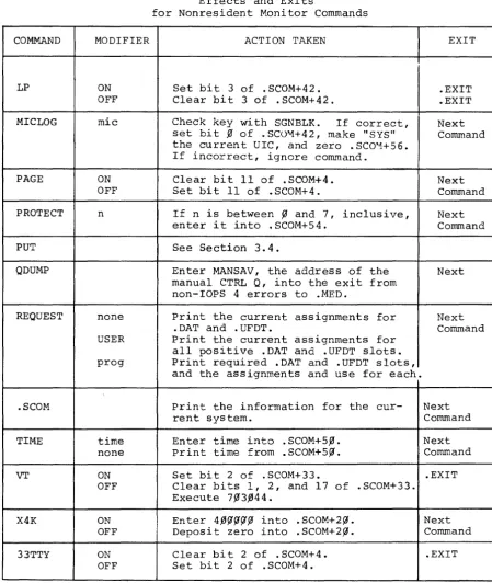
3.2 COMMANDS TO THE NONRESIDENT MONITOR
This paragraph discusses legal commands listed in the Nonresident
Monitor's Command Table. Table 3-1, Effects and Exits for Nonresident
Monitor Commands, describes all commands that do not request a new
program.
There are five entries in the Command Table that load relocatable
system programs. They are DDT, EXECUTE, GLOAD and LOAD. The
Non-resident Monitor treats these commands separately, because SYSBLK
does not list them. All information necessary for loading these
pro-grams resides in the Nonresident Monitor itself.
3.3 CONSIDERATIONS FOR ADDITIONS TO THE NONRESIDENT MONITOR
Programmers should not attempt to add commands to the Nonresident
Monitor unless they have access to a copy of the source code. The
source code may be purchased from Digital Equipment Corporation,
146 Main Street, Maynard, Massachusetts, under one of the order
num-bers listed in the footnote. They should then use the EDITO~ program
to put in the indicated changes, and reassemble.
New additions to the Nonresident Monitor require the following actions:
1. Update the Nonresident Monitor's Command Table.
The Command Table is in two parts:
a) The .SIXBT names of the commands
b) The corresponding transfer vector
2. Write the code for the command.
3. Consider the kind of exit the command will take:
DECtape
Magtape
a) Commands that end with a request for a new
command should end with JMP KLCOM
b} Commands that re-configure the Nonresident
Monitor should end with JMP NRMEX1.
DEC-15-SRDA-Ul
Unavail1.ble
COMMAND API ASSIGN BANK BATCH BUFFS CHANNEL DATE MODIFIER ON OFF handler (and/or) DIC ON OFF PR CD number 7 9 date no date
Table 3-1
Effects and Exits
for Nonresident Monitor Commands*
ACTION TAKEN
Set bit ~ of .SCOM+4.
Clear bit ~ of .SCOM+4.
Check whether handler is available. If yes, load .DAT slot with proper
handler code. (The proper loader
will load the handler, and insert its starting address into the .DAT slot.
Load proper slot via a .USER
Set bit 11 of .SCOM+4. Clear bit 11 of .SCOM+4.
Set bit ~ and clear bit 2 in
loca-tion 1777 of the Bootstrap's bank. If bit 2 of .SCOM+33 is set (i.e., if VT is ON) and bit 17 of .SCOM+33 is set (i.e., CTRL X is set for VT), set bit 1 of .SCOM+33 in order to tell the Resident Monitor Initializa-tion to start up CTRL X.
Set bits ~ and 2 of location 1777 of
the Bootstrap's bank, and set bit 1 of .SCOM+33 as with BATCH PRo
Put number indicated into .SCOM+26, and set Nonresident Monitor Initial-ization to leave .SCOM+26 alone.
Clear bit 13 of .SCOM+4. Set bit 13 of .SCOM+4
Enter date into .SCOM+47. Print date from .SCOM+47.
* This table assumes error-free input.
Table 3-1 (cont.)
Effects and Exits
for Nonresident Monitor Commands
COMMAND MODIFIER
ACTION TAKEN
EXIT
GET Set Section 3.4.
GETP GETS GETT
HALF ON Set bit ~ of .SCOM+33. .EXIT
OFF Clear bits f1 and 1 of .SCOM+33. .EXIT
HALT If not in BOSS-IS mode, put a HLT Next
instruction (instead of a JMP) into Command
the exit from non-IOPS 4 errors to
.MED. If in BOSS mode, do nothing.
INSTRUCT none Print INSALL Table. Next
ERRORS Print INSERR Table. Command
KEEP ON Set bit 16 of .SCOM+42. Next
OFF Clear bit 16 of .SCOM+42. Initial- Command
ize to SGEN default values all en-tries in .DAT and .UFDT, except change SCR default values to current UIC.
LOG Output five spaces after Carriage Next
Com-RETURNs. After ALT MODE, go to mand (after
next command. ALT MODE)
LOGIN uic Redefine current UIC (. SCOM+4l) . .EXIT
Clear bit ~ of .SCOM+42, reset
vari-able system parameters to SGEN de-fault values zero .SCOM+S6.
LOGOUT Set current UIC to SCR. Set .UFDT .EXIT
entries to SGEN default parameters. Deposit zero into .SCOM+42 and S 6.
LOGW For BOSS-IS, print message. In all Next
Com-cases, after a Carriage RETURN, out- mand (after
put five spaces. After ALT MODE, ALT MODE)
type four bells tp, and await CTRL P.
After CTRL P, go to next command.
Table 3-1 (cant.)
Effects and Exits
for Nonresident Monitor Commands
COMMAND MODIFIER ACTION TAKEN EXIT
LP ON Set bit 3 of .SCOM+42. .EXIT
OFF Clear bit 3 of .SCOM+42. .EXIT
MICLOG mic Check key with SGNBLK. If correct, Next
set bit % of . SC0"1+42 , make "SYS" Command
the current UIC, and zero . SCO"1+5 6. If incorrect, ignore command.
PAGE ON Clear bit 11 of .SCOM+4. Next
OFF Set bit 11 of . SCOM+4. Command
PROTECT n If n is between fJ and 7, inclusive, Next
enter i t into . SCOM+54. C orrun and
PUT See Section 3.4.
QDUMP Enter MANSAV, the address of the Next
manual CTRL Q, into the exit from non-lOPS 4 errors to .MED.
REQUEST none Print the current assignments for Next
.DAT and .UFDT. Command
USER Print the current assignments for
all positive .DAT and .UFDT slots.
prog Print required .DAT and .UFDT slots,
and the assignments and use for each.
.SCOM Print the information for the cur- Next
rent system. Command
TIME time Enter time into .SCOM+5,0. Next
none Print time from .SCOM+5.0. Command
VT ON Set bit 2 of .SCOM+33. .EXIT
OFF Clear bits 1, 2, and 17 of .SCOM+33.
Execute 7%3.044.
X4K ON Enter 4.f5~~~fJ into .SCOM+2~. Next
OFF Deposit zero into .SCOM+2.0. Command
33TTY ON Clear bit 2 of .SCOM+4. .EXIT
OFF Set bit 2 of . SCOM+4.
[image:30.617.74.523.88.620.2]4.
After assembly, the programmer must call PATCH, in order to make his relocatable binary program absolute. Commands to PATCH should be as follows:>DOS15)
>READR
16~77DOSNRM BIN)
16~77 indicates the highest location the new monitor
can occupy. (SYSBLK begins at 161~~.) DOSNRM BIN
happens to be the file name used by program
develop-ment. The progranuner may, of course, substitute his
own file name. More information may be found in the
PATCH manual -- DEC-15-YWZB-DN5.
3.4 QFILE
QFILE is a system program that allows users to (1) store core images
in named files, and (2) retrieve such core images for examination via
DUMP (or possibly for a slow, core-swapping capability). QFILE
imple-ments the following Resident Monitor system macros and Nonresident
Monitor commands:
.GET, GET, GETP, GETS, GETT, .PUT and PUT
Users can not obtain QFILE by typing its name to the Nonresident
Monitor. The Resident Monitor will load QFILE as part of its response
to the commands and macros listed above.
PUT creates a file that contains the data in the CTRL QAREA; .PUT
creates a file from the current core image. GET, GETP, GETS, GETT
and .GET all overlay core with the contents of the QAREA or file. (The
different commands specify different startup locations.) In addition
to the above capabilities, the Resident Monitor provides the capability
of overlaying core with the contents of the CTRL Q area. The
follow-ing instructions show how to use that routine:
UNITNO=4~~~f1~ .SCOM=l~~
LAC
XOR JMP*
START
UNITNO
(. SCOM+6 4
/UNIT FOUR
/STARTING ADDRESS AFTER THE CTRL Q /GET
/UNIT NUMBER IN HIGH-ORDER THREE BITS /ADDRESS OF CTRL Q GET ROUTINE
Figure 3-2, QFILE, and Implementation of GET and PUT Logic, shows the information flow associated with QFILE. QFILE uses the
follow-ing registers:
. SCOM+7 , l~ & 11 .SCOM+65
.SCOM+66-71 .DAT-14
.SIXBT Filename and Extension
Command parameters, packed as follows: Bits ~-2 Device unit number Bit 8 NRM PUT, when set Bit 9 PUT logic, when set Bits 15-17 Function Code
CTRL Q Area parameters
File must be on the device assigned to this .DAT slot.
NOTE
Store unit number and code into
.SCOM+65
1.
2.
.PUT CAL
store unit number and function code into
.SCOM+65
Set bit 9 of .SCOM+65
to indicate .PUT
N
Dump core into CTRL Q area
Bring in QFILE via a .OVRLA
GET PUT
1. Store unit number an
function code into
• 5 COM+ 65
2. Set bits 8 and 9 of
.SCOM+65 to indicate
NRM PUT
1. Save .SCOM+65 from the file
2. Transfer core image file to
crRL Q area via dump mode .READ's and Monitor TRAN's.
Transfer core image from CTRL Q area to named file via Monitor TRAN's and dump mode .WRITE's
N
Use function code from file's .SCOM+65
1. Store correct startup address
2. Do Monitor TRAM from CTRL Q
Note: This chart assumes error free input.
QFILE, and Implementation of GET and PUT Logic
Figure 3-2
CHAPTER
4
THE SYSTEM LOADER AND THE LINKING LOADER
The System Loader is the third major part of the 00S-15 Monitor. The
other two are the Resident and Nonresident parts. The Resident and
Nonresident Monitors communicate with the System Loader by
manipulat-ing certain .SCOM registers. When comm&nds to either part imply a
new configuration is needed, that part sets up the appropriate .SCOM
registers, and passes control to the System Bootstrap via the Monitor
TRAN routine. The Bootstrap then loads the System Loader into high
core, and gives i t control.
The System Loader examines the .SCOM registers, and loads a fresh copy
of the Resident Monitor, including any features that the user wishes
to be resident, such as the CTRL X feature. It will also load the
desired system program and a~l handlers required by the new
configura-tion. In addition, i t will allocate all required buffers. The
Non-resident Monitor is treated like any other core-image system program.
The System Loader never loads user programs. It only loads core-image
system programs, the Linking Loader and Execute. The latter two load
user programs~
The System Loader uses two device handlers to interface with the disk:
the System Bootstrap, and the System Loader Disk Handler (DKL.). OKL.
arrives in core along with SYSBLK, COMBLK and SGNBLK, as well as the
loader itself. The Bootstrap loads core image programs only. The OKL.
takes care of relocatable programs and any handlers loaded by the
System Loader. Those include all handlers for core-image system programs,
the Linking Loader's own handlers, and any needed by the Execute file.
The Linking Loader loads some handlers needed by user programs i t links.
There are two parts to the System Loader: the System Loader Interface,
and the System Loader proper (.SYSLD). Figure 4-1 describes the System
Loader Interface. Figure 4-2 describes the System Loader Proper, and
Figure 4-3 describes the Linking Loader.
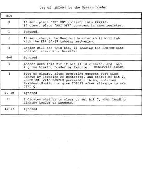
Turn on the clock Initialize
.SCOM+~
.SCOM+4
.SCOM+2~
First free reg-ister below the Bootstrap SGEN default Bit zero set, i extra 4K: rest zero
.SCOM+33 VT & HALF, as
per SGEN
.SCOM+74 Line frequency
-Mov to hi hest bank
Zero .SCOM+36, to indicate no entries in Busy Table
2. Move Resident Monitor into lower core
3. Set up: Jump to Skip Chain
CAL* error Legal CAL jump
4. Turn API on or off, depending on bit ~ of .SCOM+4 (set=on)
5. Bank bit initialize Resident Monitor to talk to the
Bootstrap, and load .SYSLD into the proper bank upon a subsequent .EXIT or .OVRLA.
6. Initialize the Bootstrap with the proper lOPS 4 address for
disk not ready
7. Calculate the Skip Chain from SGNBLK
8. Set all API channel registers to point to lOPS 3 (with the
exception of the clock interrupt) and all software levels
to point to lOPS 3~
9. Put transfer vector to .DAT slots into .SCOM+23
l~. Put number of positive ~DAT slots into .SCOM+24
11. Put pointer to .UFDT+~ .into .SCOM+25
.TRAN image of .OAT and • UFDT in from block 37 of the
sys-tem device unit ~
1.
2.
3.
N
Zero .OAT-7 (i.e., not yet set up) set up .DAT-2 and .DAT-3 for TTA. Update .SCOM+l and +2 to point just-above the Skip Chain, .DAT and .UFDT
Next Page
System Loader Initialization
Figure 4-1
From Preceding Page
1. Put number of system device's "A" handler (DKA. or DPA.) into .SCOM+57
2. Set up tabbing for current teleprinter
3. Set .SCOM+2~ to initial state (as in first t~e initialization)
4. Set up for CTRL Q -- ignore Q-dumps if RF system and QAREA too
small, or nonexistent
5. Setup for lOPS errors upon the followinG interrupts:
Nonexistent Memory (lOPS 31)
Memory Protect Violation (lOPS32)
Memory Parity Error (lOPS33)
Power Fail Not Set
Up
(lOPS34)N
N
Y
Y -- Non-BOSS Batch
Set up for the proper input device (CD or PR)
19-nore input until $JOB
N~tP~e
From Preceding Page
1. Set up CTRL C to clear the Batch Switch (bit 1 of 17777
of the Bootstrap)
2. set up CTRL T to abort current job, and start the Batch Monitor looking for the next $JOB line
3. Relocate proper batch handler (PR or CD) to low core
4. Put handler entry point into .DAT-2
5. Set lOPS errors to abort job -- effectively a CTRL T 6. Set up all batch device .DAT slots to refer to the
hand-ler currently in core. That is, only one batch input
device is allowed at anyone time
7. Clear $JOB read switch (bit 1 of Bootstrap 17777) 8. Perform .INIT to .DAT-2
N
1. Relocate Resident BOSS
and link it to the DOS Resident Monitor
2. Patch DOS Resident
Mon-itor to accomodate BOSS
3. Set bits 14, 15 and 17
of .SCOM+42, to tell .SYSLD to set up .DAT-7 and +6
N N
Relocate and link CTRL X code, and give proper buffer
Set up linkages between CTRL X code and the Resident Monitor
Next Page
System Loader Initialization
Figure 4-1 (Cont.)
From Preceding Page
1. Allocate the number of buffers
indicated by .SCOM+26
2. Set up File Buffers Transfer
Vector Table pointer, in .sCOM+3~
N
3. Store one of the following codes
into .SCOM+6:
LOAD l~~~~~
GLOAD 3~~~~~
Tell .SYSLD by setting .SCOM+ll to XCS (avoids two handlers in core for same device)
DDT 4~~~~~
DDTNS 5~~~~~
4. Zero .SCOM+5 1. Allocate number of
buffers indicated by .SCOM+26
~ __________________ ~ __ ~ __ ~ ____________ ~2. Set up File Buffers
Transfer Vecter
Table in .SCOM+3~
3. Set .SCOM+6 =
m
(Loading a Core-Image Program) 1. Find entry in SYSBLK and COMBLK
2. Build Overlay Table from information in COMBLK, and set .SCOM+31 to first word in the table
3. Store the number of overlays in the overlay processor of the Resident Monitor
1. Store the list of active .DAT slots de-rived from COMBLK in the System Loader
command area, just below the ~ootstrap,
and delimit the list with a zero 2. If the Nonresident Monitor was not the
last program, restore .SCOM+26 ~default
3. Allocate space for, and set up .SCOM+3~
to point to the File Buffers Transfer Vector Table
Next age
System Loader Initialization
Figure 4-1 (Cont.)
From Preceding Page
1. Zero .SCOM+6
2. Put 1
into .SCOM+5
1. Move the RCOM Table to position below
the Bootstrap
2. Build the IOC Table
System Loader Initialization
1. set up for Page or Bank Mode
2. Set up .DAT-7 for the System Loader disk handler COXA. or OPA.)
3. Clear free core, and initialize bank bits in pointers to the Bootstrap
4. Make a Mass Storage Busy Table consisting of one entry
1. Change XCS to XCT
2. Allow reading of
EXECUTE file by the System Loader Handler
Clear memory bank pointers of banks that do not exist
N
Load handlers into extra 4k,
N
Put System Device's code into
.DAT+~, to allow subsequent insertion into .DAT-7
Next Page The System Loader
From Preceding Page
core- EXECUTE
image
N
1. Translate the handler code from radix
5~ to .SIXBT
N
2. Do .USER to .UFOT-7, using "lOS"
3. Do .INIT and .SEEK to .OAT-7, in order
to get the handler file
4. Load handler via .OAT-7, and close .OAT-7
N - - not
Note: Subroutine IOPROS accepts
.OAT slots as input. If the
in-dicated .OAT slot contains zero, the slot is unassigned, and IOPROS
returns. If not zero, IOPROS checks---~
whether the desired handler has
al-ready been loaded. If the handler
is in core, IOPROS loads the .OAT slot with the handler's starting
ad-dress and returns. If the handler has
not been loaded, the handler code is made an unresolved .GLOBL, to be satisfied by the loop that follows immediately.
The System Loader Figure 4-2 (Cant.)
4-8
1. Set up Mass storage Rusy
Table Entries for all active .OAT slots
2. Set .SCOM+l to first free
location in core--often becomes first location of EXECUTE
From Preceding Page
Load and relocate EXECUTE or the Linking Loader, and place starting address into .SCOM+5
N
1. set up Mass Storage Busy table with one entry per active .DAT slot
2. Move the IOC table from the System
Loader's area (just beneath the Bootstrap) to the Linking Loader's area
set .SCOM+2 and +3 to delimit free core
dress in SCOM+5
1. Allocate all necessary buffers
2. If the system has an extra 4K,
put the first free address beneath
the handlers into .SCOM+2~
3. Update first free location in core
shown in .SCOM+2 -- .OVRLA updates
the first free address beneath the Bootstrap, .SCOM+3
Exit via .OVRLA
Note: Subroutine BaseKl does the following, if loading a program under BOSS-15:
(1) .USER to .UFDT-7, (2) .SEEK to .DAT-7 for PRCFIL PRC.
The System Loader
STARr
1. Clear all of core above the loader, including the extra 4K, if present, and excluding the Bootstrap ,
2. Initialize the Load Table with the first free address in every bank or page
3. Indicate all core below the address in .SCOM+2 as not free
4. Compute transfer vectors to .OAT-l, -3, -4, -5, and -7, and a pointer to
.UFDT-l
5. Save the contents of .UFDT-l
1. Check for P, G and C switc es
N
Load DDT and set the symbol flag, if not ODTNS
Type appropriate name, and await command string
2. Translate all file names after left arrow into .SIXBT, pad with blanks, and store in symbol table
3. After ALT MODE, load to end-of-file each file on .DAT-4, and put starting address of the first file (i.e., not DDT) into .SCOM+6
N
After every end of tape, type tp and await CTRL P -- continue until number of tapes equals the number of commas, plus one
Next Page
The Linking Loader
Figure 4-3
NOTE:
During the library searches diagrammed on this page, the Linking Loader tests for more unresolved .GLOBL's af-ter each resolution. When-ever there are no more unre-solved .GLOBL's, the Linking Loader halts its library searches, and goes directly to the COMMON area allocation code (next to the last box on this page). Thus, the libraries are never searched more than is necessary.
From Preceding Page
Check Symbol Table for handlers needed, and load them from .DAT
-1, using lOS as a UIC; exit if
ille al .DAT desired
y
Check Symbol Table for any unresolved .GLOBL's
y
1. Do .SEEK to LIBRS BIN on .DAT-S
2. Read through user's library and
load any program units that sat-isfy any .GLOBL's
3. Read to end of library file, if
still unresolved .GLOBL's
If any unresolved .GLOBL's, try to
~---~~---~find program units in the system library (.LIBR BIN) on .DAT-l
Exit to the~ ______ - 1 Print LOAD3 error
Nonresident message
Monitor
~---Scan Symbol Table for Common Blocks, and allocate space and set pointers,
as needed. If any unresolved .GLOBL's
seek matches in the Common Blocks
y
Next Page The Linking Loader
y
From Preceding Page
set .SCOM+2 above the Loader's highest hand-ler -- no handhand-ler is overlayed
Allocate the Mass Storage Busy Table, with the number of entries equal the sum of the active .DAT slots, minus one -- i.e., the two .DAT slots for the teleprinter are omitted, and one for .DAT-7 is added
GLOAD
Put lowest address of the Symbol Table into .SCOM+II, and the high-est into .SCOM+2 --DDT will recalculate .SCOM+2
The Linking Loader
Figure 4-3 (Cont.)
4-12
LOAD
4.1 MANUAL BOOTSTRAP LOADS AND RESTARTS
Manual Bootstrap loads and restarts bring blocks ~-36 of the system
device into the lowest bank. These blocks contains the Resident
Moni-tor, the System Loader Interface Routine, and SYSBLK, COMBLK and SGNBLK.
Figure 4-4 illustrates the core load after manual Bootstrap loads and
restarts. The Interface sets up .SCOM+~, 4, 2~, 27, 33, 54 and 74
from SGNBLK values determined at system generation time, and then
transfers the whole core image of the Interface to the Bootstrap's
bank. (DOS requires 16K, because this bank must be different from
bank ~.) At all other times, the Bootstrap loads the System Loader
into its own bank. This preserves the image of .SCOM, part two of
the Resident Monitor patch ~ea, and the CTRL X buffer.
4.2 LOADING SYSTEM PROGRAMS
The System Loader Interface Routine gets control in the highest bank,
either by a transfer from the lowest bank, or by load from the
Boot-strap. After setting up for the System Loader Proper (.SYSLD),
accord-ing to the program to be loaded and the settaccord-ings of certain SCOM
regis-ters, the Interface Routine brings i t in as a complete overlay. Figure
4-5 illustrates the core configuration of the Interface when i t is
in the highest bank. (The addresses provided are for a 16K system.)
The System Loader loads handlers from the lowest part of free core up,
with the exception that the extra 4K is filled first, if i t exists.
Core image system programs are usually loaded just beneath the Bootstrap
(always in the highest bank). Such core images must be wholely within
the top bank of core, and above register 17 of that bank. Figure 4-6
illustrates the core maps for system programs.
Whenever the Linking Loader is loaded (LOAD, GLOAD, DDT, and DDTNS) ,
the System Loader loads all handlers for .DAT slots -1, -4, and -5,
and then loads the Linking Loader itself. (DDT is loaded by the
Linking Loader.) Figure 4-7 illustrates the core maps for the Linking
Loader.
For EXECUTE, the System Loader loads EXECUTE's handler, and reads the
EXECUTE file, in order to determine the active .DAT slots. The System
Loader then loads all the handlers required, and sets up the .DAT
slots. Figure 4-8 illustrates core maps for EXECUTE.
BOOTSTRAP
UNUSED
3 SYSTEM BLOCKS
SYSTEM LOADER INTERFACE
RESIDENT MONITOR
16K. 24K. 32K
.SCOM
17500
16100
100
15-0663
Figure 4-4
Bootstrap Load
BOOTSTRAP
SYSTEM PROGRAM (THIS AREA IS USED BY CORE IMAGES. SOME ROOM UNDERNEATH THE BOOTSTRAI' MAY BE LEFT FREE FOR COMMUNICATION BETWEEN CORE IMAGES IN AN OVERLAY STRUCTURE. CORE IMAGES MUST BE BK OR LESS.)
FREE CORE
HANDLERS, BUFFERS
BUFFER POOL TRANSFER VECTORS
OVERLAY TABLE
DEVICE TABLE
RESIDENT MONITOR
Figure
4-6
System Program Load
16K, 24K, 32K
.SCOM . SCOM+3 .SCOM+2 .SCOM+l 15-0661 BOOTSTRAP
DDT, IF PR ESENT
1
LOADED PROGRAMS
ON DDT LOADS. SYMBOLS ARE MOVED INTO THE LOWEST PART OF FREE CORE.
SYMBOL TABL E SYMBOLS AND PROGRAMS BUILD TOWARD EACH OTHER.
i
LINKING LOADER"
LOADER HANDLERS
BUFFER POOL
BUFFER POOL TRANSFER VECTORS
RESIDENT MONITOR
·Placement of .SCOM+2 depends on relative
positions of the Linking Loader and its handlers .
When control is nansfertad to loaded program, SCOM.2 and +3 bracket 1ree core
Figure 4-7
Linking Loader
16K, 24K. 32K
.SCOM .SCOM+3·
.SCOM+2· .SCOM+l 15-0660 BOOTSTRAP .ReOM TABLE SGNBLK
SYS3LK and COMBLK
SYSTEM LOADER INTERFACE
(overlayed by .SYSLD)
RESIDENT MONITOR IMAGE
RESIDENT MONITOR
• A s the I n1erhce moves code down, It Inere ments .SCOM+l and +2.
Figure 4-5
Standard
Interface Load
BOOTSTRAP
OVERLAY SYSTEM BLANK COMMON
FREE CORE
EXECUTE
All HANDLERS REQUIRED
BUFFER POOL
BUFFER POOL TRA'IISFE R VECTORS
RESIDENT MONITOR
Figure 4-8
Execute
16K, 24K. 32K
.sCOM
37500 (16K)
37100 (16K)
36100 (16K)
20100 (16K)
.SCOM+l.2 •
15-0664
16K. 24K, 32K
.SCOM
.SCOM+3
.SCOM+2
.SCOM+l
BOSS-IS Mode operation requires the system "A" handler be assigned to
.DAT-7. This requires a sleight of hand on the part of the System
Loader, which needs the "L" handler on .DAT-7. It therefore loads
the "A" handler as if i t were assigned to .DAT+P', and transfers the
set up .DAT slot ~ contents to .DAT-7 before transferring control to
the program being loaded. .DAT+~ is then restored to its original
status.
4.4 TABLES AND INFORMATION BLOCKS USED AND BUILT BY LOADERS
The System Loader uses SYSBLK, COMBLK, SGNBLK, block 37 of the system
device, .SCOM, the RCOM Table, the IOC Table, the Device Table, the
Mass Storage Busy Table, the File Buffers Transfer Vector Table, the
Overlay Table, .DAT, .UFDT and three bits in the Bootstrap. Tables
4-I, 4-I1 and 4-II1 describe how the Loaders use these blocks and tables.
4.5 .DAT SLOT MANIPULATION BY THE SYSTEM LOADER
The System Loader maintains the .DAT slot device handler assignments
as they were the last time the Nonresident Monitor was in core. The
Loader saves the .DAT and .UFDT on the system device whenever the
Nonresident Monitor was the last program. in core. Thereafter, the
Loader refreshes .DAT and .UFDT from the image on the disk. If KEEP
is off, the Nonresident Monitor's initialization routine restores the
.DAT and .UFDT to default values.
When loading core-image system programs, the System Loader determines
the active .DAT slots by examining COMBLK. When loading EXECUT, the
System Loader sets up .DAT-4, and any active slots indicated by the
Execute file itself. wnen loading the Linking Loader, the System
Loader sets up .DAT-l, -4, and -5. The Linking Loader will set up other
other active .DAT slots according to the .IODEV commands in the
as-sembly of the program units being loaded.
Both the System Loader and the Linking Loader set up .DAT slots in
this manner:
one. )
NAME
SYSBLK
COMBLK
SGNBLK
Block 37 of the Sys-tem Device
. SCOM Table
RCOM Table
laC Table
Device Table
Mass Storage Busy Table
File Buffers Transfer Vec-tor Table
Overlay Table .DAT and .UFDT BOOTSTRAP
Table 4-1
Tables and Used by the
USE
I
Block? Loaders
I
The System Loader obtains Monitor TRAN parameters from SYSBLK when i t builds
Indicates number of buffers required, the active .DAT slots, and the names
Default settings for .SCOM registers, number of words per buffer, size of Resident Monitor's patch area (part two), Skip Chain, .DAT and .UFDT de-fault contents, and handler informa-tion.
Image of .DAT and .UFDT, when last pro-gram was loaded (excluding the Nonresi-dent Monitor).
See Table 4-11 .
LOCATION
16S99 of .SYSLD's bank
171~f1 down, in .SYSLD's bank
16199 of .SYSLD's bank
l.0f1 of 1st bank
Moved for use by the Nonresident Monitor. 175f1f1 of the highest bank
Built by Interface Routine for .SYSLD itself.
Built by Interface Routine if loading PIP, or if PIP is among the overlays listed in COMBLK
Built by the System Loader itself.
Allocated by the Interface Routine, and initialized by i t for non-core Image
programs. System Loader proper
initial-izes for core-image programs.
Built by the Interface Routine
Image stored and restored from block 37
of the System Device. The System Loader
loads all handlers for core-image pro-grams and EXECUTE Files, and sets up
the appropriate .DAT slots. The System
Loader also loads handlers assigned to .DAT-l, -4, and -5 when loading the Linking Loader, and .DAT-7 and +6 for BOSS-IS.
Bits
fI,
I, and 2 of location 17777 inthe Bootstrap's bank used for Batch (non-BOSS) information.
4-16
Just beneath the System Loader
Just above .SCOM+l
Pointed to by .SCOM+62
Pointed to by .SCOM+39
Pointed to by .SCOM+31
Table 4-11
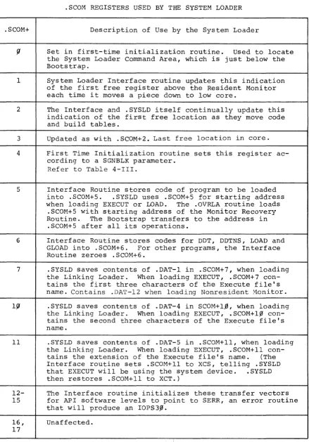
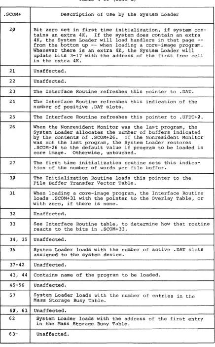
.SCOM REGISTERS USED BY THE SYSTEM LOADER
.SCOM+ Description of Use by the System Loader
f! Set in first-time initialization routine. Used to locate
the System Loader Conunand Area, which is just below the Bootstrap.
I System Loader Interface routine updates this indication
of the first free register above the Resident Monitor each time i t moves a piece down to low core.
2 The Interface and .SYSLD itself continually update this
indication of the first free location as they move code and build tables.
3 Updated as with .SCOM+2. Last free location in core.
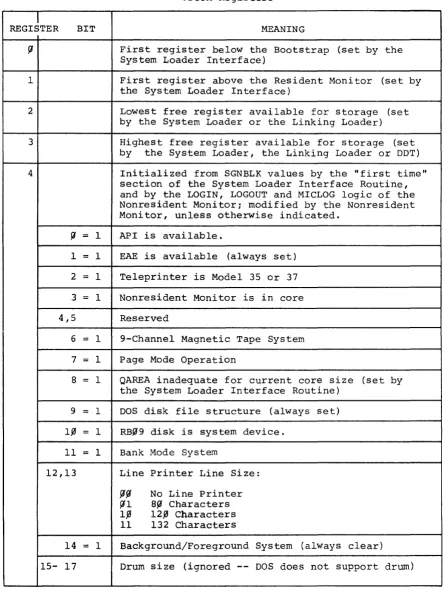
4 First Time Initialization routine sets this register
ac-cording to a SGNBLK parameter. Refer to Table 4-III.
5 Interface Routine stores code of program to be loaded
into .SCOM+S. .SYSLD uses .SCOM+S for starting address
when loading EXECUT or LOAD. The .OVRLA routine loads
.SCOM+S with starting address of the Monitor Recovery
Routine. The Bootstrap transfers to the address in
.SCOM+S after all its operations.
6 Interface Routine stores codes for DDT, DDTNS, LOAD and
GLOAD into . SCOM+6. For other programs, the Interface
Routine zeroes . SCOM+6.
7 .SYSLD saves contents of .DAT-I in .SCOM+7, when loading
the Linking Loader. When loading EXECUT, .SCOM+7
con-tains the first three characters of the Execute file's name. Contains .DAT-12 when loading Nonresident Monitor.
If! .SYSLD saves contents of .DAT-4 in SCOM+l,0, when loading
the Linking Loader. When loading EXECUT, .SCOM+l,0
con-tains the second three characters of the Execute file's name.
11 .SYSLD saves contents of .DAT-5 in .SCOM+ll, when loading
the Linking Loader. When loading EXECUT, .SCOM+ll
con-tains the extension of the Execute file's name. (The
Interface routine sets .SCOM+ll to XCS, telling .SYSLD
that EXECUT will be using the system device. .SYSLD
then restores .SCOM+ll to XCT.)
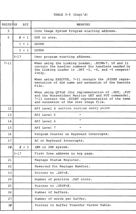
12- The Interface routine initializes these transfer vectors
15 for API software levels to point to SERR, an error routine
that will produce an IOPS3,0.
16, Unaffected.
[image:50.613.83.522.110.739.2]