A technique to compare polythiophene
solid-state dye sensitized TiO
2
solar cells to liquid
junction devices
Greg P. Smestad
a,*, Stefan Spiekermann
b,1, Janusz Kowalik
c,
Christian D. Grant
d, Adam M. Schwartzberg
d, Jin Zhang
d,
Laren M. Tolbert
c, Ellen Moons
eaSol Ideas Technology Development and Solar Energy Materials and Solar Cells, P.O. Box 51038,
Pacific Grove, CA 93950, USA
bSwiss Federal Institute of Technology, EPFL-ICP-2, CH-1015, Lausanne, Switzerland cSchool of Chemistry and Biochemistry, Georgia Institute of Technology, Atlanta, GA 30332-0400, USA
dUniversity of California Santa Cruz, Department of Chemistry and Biochemistry, Santa Cruz,
CA 95064, USA
eDepartment of Physics, Institute of Engineering Sciences, Physics and Mathematics, Karlstad University,
SE-651 88 Karlstad, Sweden
Received 7 January 2002; received in revised form 20 April 2002
Abstract
In this communication, we report on a technique to fabricate solid-state polythiophene-based dye sensitized solar cells (DSSCs) that can be directly compared to analogous liquid junction devices. The device configuration is based on non-porous TiO2thin films and one of
the three undoped polythiophene hole conductors: poly[3-(11 diethylphosphorylundecyl) thiophene], P3PUT, poly(4-undecyl-2,20-bithiophene), P4UBT, or poly(3-undecyl-2,20 -bithio-phene), P3UBT. These polymers were spin coated and cast from organic solutions onto the TiO2films. The dense TiO2thin films (ca. 30 nm) were deposited on conductive glass via facile
spray pyrolysis and sol–gel techniques. After that, cis-(SCN)2 Bis(2,20 bipyridyl-4,40
-dicarboxylate) ruthenium(II) (a.k.a. Ru N3 dye) was adsorbed on the TiO2surface, and the
polythiophenes were utilized as hole conductors in a simplified solar cell geometry. The results were compared to the control DSSC device made with dense TiO2and a liquid electrolyte, or
*Corresponding author. Phone: +1-415-979-8730.
E-mail addresses:[email protected] (G.P. Smestad), [email protected] (S. Spiekermann), [email protected] (J. Kowalik), [email protected] (J. Zhang), [email protected](L.M. Tolbert), [email protected] (E. Moons).
1Present address: SusTech GmbH & Co. KG, c/o Technische Universitat Darmstadt, Petersenstra. e 20,
D-64287 Darmstadt, Germany.
0927-0248/03/$ - see front matterr2002 Elsevier Science B.V. All rights reserved. PII: S 0 9 2 7 - 0 2 4 8 ( 0 2 ) 0 0 2 5 2 - 0
2,20,7,70-tetrakis(N,N-di-p-methoxyphenylamine)-9,90-spirobifluorene (a.k.a. Spiro-MeO-TAD). The polythiophenes exhibited bandgaps in the range 1.9–2.0 eV, and HOMO energy levels of approximately 5 eV (vs. vacuum). The P3PUT DSSC device exhibited an AM1.5
VOC¼0:8 V, a JSC¼0:1 mA/cm2, as well as an IPCE=0.5–1%. The AM1.5 short-circuit
photocurrents and quantum efficiencies for DSSCs made with the polythiophenes, the Spiro-MeOTAD and the standard liquid electrolyte (I=I3) were found to be identical within the limits of experimental uncertainty and reproducibility. Our results indicate that a solid-state replacement to the liquid junction is not necessarily limited by the fundamental aspect of hole transfer, one of the three fundamental aspects that must be met for an efficient DSSC. Rather than suggest that P3UBT or P4UBT could be used to create efficient ‘‘organic solar cells’’ with the exclusion of the Ru dye, we suggest that transparent thiophene compounds could be attractive candidates for high-surface area solid-state DSSCs, and that the technique presented can be applied to other hole conductors. It can allow a verification of one of the things necessary for the DSSC, so that parallel studies using high-surface area materials can proceed with confidence.r2002 Elsevier Science B.V. All rights reserved.
Keywords:Dye sensitized solar cells; Organic solar cells; Polythiophenes; Conductive polymers; Titanium dioxide (TiO2)
1. Introduction
There is an increasing interest in using organic and ‘‘plastic’’ materials for optoelectronic devices. Electroactive organic compounds are being investigated in photovoltaic (PV) solar cell technologies [1–9], and in novel light emitting diodes (LEDs), and field effect transistors (FETs) [10]. In recent years, combinations of semiconducting polymers, such as poly(p-phenylene)vinylene (PPV), with nanopar-ticles of wide bandgap inorganic semiconductors, such as CdS, and TiO2, have been investigated for solar cell applications [4–5], as well mixtures of PPV-derivatives with C60 [9], and blends of polymer materials [6–8]. Although open-circuit voltages in PPV-based PV devices are impressive (0.8–1 V), the AM1.5 photocurrents have not exceeded a few mA/cm2due to the low mobility in the organic material, as well as insufficient charge carrier production in the 600–800 nm wavelength range.
Another approach to low-cost organic PV devices is based on the sensitization of a high-bandgap material, such as nanocrystalline TiO2or ZnO, with organic dyes such as cis-(SCN)2Bis(2, 20bipyridyl-4,40-dicarboxylate) ruthenium(II) (a.k.a. Ru N3 dye) [1–3]. In this case, only a monolayer of the dye is utilized on the high-surface area semiconductor support, so photon induced charge carrier production and transport are carried out by two different materials. A dye sensitized solar cell (DSSC) based on nanocrystalline TiO2exhibited an AM1.5JSC of over 16 mA/cm2and an overall sunlight to electrical energy conversion efficiency of 7–10%, as well as quantum efficiencies of 80–90% from 400 to 700 nm [1,2]. While this conversion efficiency is lower than the 15% of standard Si PV [11], it offers advantages including environmentally friendly components, low-temperature processing, and potentially lower costs to consumers. Our prior work indicates that solar cells of at least
10–12% efficiency could be realized at less than $3/W cost [12], making the DSSC competitive with fossil fuel electricity generation. Since renewable energy sources can play a significant role in our future energy portfolio [13,14], the successful development of the DSSC could have important ramifications if the limitations to its commercial development can be overcome. The existing state of the art for DSSC PV technology utilizes an iodide redox mediator dissolved in organic liquids to transport holes away from the sensitizing Rudye attached to the nanocrystalline TiO2(see Fig. 1a). One limitation of this DSSC approach is the use of low viscosity volatile liquid solvents such as acetonitrile that allow for an efficient solar cell energy converter, but may be difficult to seal and maintain [2,3]. Unpublished work by our group has involved the use of Surlyn 1702 (Dupont) to seal liquid-based DSSC devices, but this was found to be inadequate for stable 10% (AM1.5) efficient outdoor devices. Other investigators have replaced these liquids with various hole conducting solids such as 2,20,7,70-tetrakis(N,N-di-p-methoxyphenylamine)-9,90 -spirobifluorene (Spiro-MeOTAD) [3], PPV [4,5], CuI or CuSCN [15–17], and gels [18]. These studies, several of which produced high photocurrents (JSC>4:5 mA/ cm2), leave one to question which aspect of the hole conductor needs to be improved if further advancements are to be made.
Our prior investigations involved replacing the liquid in the DSSC with suitable substituted polythiophenes [19]. The use of polymers in DSSCs has been reported previously, and polythiophenes have been used in DSSCs by researchers such as Spiekerman, Gebeyehu, and Sicot [19–21]. We desired, however, to clearly determine if hole transfer to the Rudye can efficiently occur via the polythiophene, with the
I=I
3 liquid electrolyte, currently used in efficient devices, as a reference for this determination. In addition, we wished to establish if the polymer hole conductor itself absorbs light and can sensitize the TiO2as efficiently as the Rudye. If this is not the case, the hole conductor interferes or competes with the Ru dye for light absorption and this effect complicates DSSC experiments that compare liquid and polythiophene hole conductors using nanocrystalline materials.
We wished to determine if the first step in the interaction between the dye and polythiophenes is as favorable as it is for other hole conductors such as the liquid electrolyte and Spiro-MeOTAD. As shown in Fig. 1a, three parameters (aspects) are essential for any hole conductor in the DSSC: (1) it must be able to transfer holes from the sensitizing dye after the Rudye has injected electrons into the TiO2, (2) it must be able to be deposited within the porous nanocrystalline material, and (3) it must be transparent, or, if it absorbs light, it must be as efficient in electron injection as the Ru dye. Our chosen experimental configuration was selected to address only the first and third items in an effort to understand the limitations of these types of materials (e.g. polythiophenes) that have been used in porous, high-surface area DSSCs and in organic solar cells.
As shown in Fig. 1b, the light passes only once through our device configuration, first through the TiO2and dye, and then through the hole conductor. This approach can provide fundamental information towards answering the basic question as to what limits hole conducting materials [1–5,15–19] as replacements for the liquid junction-based DSSC. This configuration is not necessarily one that would be used in
a practical DSSC or PV applications, but it provided us with useful insights for the rational selection of materials for solid-state DSSCs. We have utilized two different types of undoped substituted polythiophene polymers, a phosphonated Fig. 1. (a) A schematic of the dye sensitized solar cell (DSSC) configuration used with nanocrystalline, or porous, TiO2. The hole conductor can be theI=I3in the case of the liquid cell, or a solid, such as a
conjugated polymer, in the case of the solid-state DSSC. Light enters through the TiO2side, and passes
through many layers before it is absorbed. The Ru dye (dark circles) is adsorbed on the surface of the TiO2
before application of the hole conductor. Also shown are the necessary aspects of the hole conductor: (1) hole transfer and transport, (2) pore filling, and (3) transparency. See text for further details. (b) Solar cell configuration used with the non-porous TiO2 and hole conductors in the present study. Light enters
through the TiO2side, and passes only once through the device. The Ru dye (dark circles) is adsorbed on
the surface of the TiO2before application of the hole conductor. Black tape masks defined the input
aperture and carbon contact areas (of area 0.25 cm2). For the liquid junction ‘‘control’’ cell, acetonitrile andI=I
3 is the hole conductor, and a SnO2:F glass plate coated with a catalytic Pt layer replaces the
carbon contact [1,12,26]. This device therefore allows one to determine the role of a single TiO2/dye/hole
polythiophene, P3PUT [22], and alkyl substituted polythiophenes P3UBT and P4UBT [23]. The structures for these polymers are shown in Fig. 2.
2. Experimental methods
The preparation of the P3UBT, P3PUT and P4UBT has been reported previously [22–24]. The P3PUT and P4UBT were 90% stereoregular, while the P3UBT was regio-random. For both polymer characterization and solar cell fabrication, the polythiophenes were not doped intentionally. That is, no substances were added that are known to act as dopants. Chloroform (CHCl3) and tetrahydrofuran (THF) were used as solvents for polymer thin film deposition. UV-visible spectroscopy was performed on a thin (20–25 nm) film of the polymers using a Hewlett-Packard diode array spectrophotometer. The electrochemical analysis was performed using a Solartron SI 1280B on thin films of the polymers deposited from solution on SnO2:F conductive glass. An Ag/AgCl reference electrode (isolated by a frit tube) was employed in the standard three-electrode arrangement, with 0.1 M tetrabutylammo-nium tetrafluoroborate (TBATfB), in acetonitrile (reagent grade), serving as a supporting electrolyte. Ultrafast experiments were performed with a regeneratively amplified, mode-locked femtosecond Ti-sapphire laser with experimental and system setup described elsewhere [25,26]. The pump wavelength was 390 nm and the probe wavelength was 790 nm. Work function measurements were performed in a glove Fig. 2. Polythiophene polymers: poly[3-(11 diethylphosphorylundecyl) thiophene], P3PUT, poly(4-undecyl-2,20-bithiophene), P4UBT, or Poly(3-undecyl-2,20-bithiophene), P3UBT utilized in the present
box (Ar atmosphere) by the Kelvin probe technique using a vibrating gold electrode, as described previously [27,28].
Thin films of TiO2were deposited onto the SnO2:F conducting glass (LOF TEC 15, Hartford Glass) by spray pyrolysis [29]. A 10% solution of di-iso-propoxy titanium-bis(acetylacetone) in ethanol (ca. 4 ml) was sprayed onto the conducting glass (75 cm2) preheated to 4501C and covered along the long edges to enable electric contact. The resulting glass plates were then cut into electrodes (12.5 cm2). As an alternative to the spray pyrolysis method, TiO2thin films were also deposited via a sol–gel procedure [30]. Substrates for sol–gel TiO2film deposition were masked off with tape and mounted on the spin coater. They were then washed with deionized water followed by isopropanol, a total of three times, at an angular speed of 1000 rpm. The sol–gel mixture was prepared by a successive addition of absolute ethanol 250ml milli-Q H2O, acid (HNO3or HCl to bring the pH to between 1 and 2), followed by titanium isopropoxide (TIP) (750ml) to a stirred absolute ethanol (10 ml) solution, with cooling (01C). Addition of TIP was done under nitrogen in a glove box. The mixture was then stirred for 1 day at 01C prior to use. The resulting solution (100ml) was then applied on a spinning (1000 rpm, 60 s) substrate followed by firing for 30 min at 4501C. The thickness of the films was 30–40 nm. The performance of the TiO2 films was verified by cyclic voltammetry. As a quality control, if the TiO2film was indeed dense, it blocked the passage of 0.1 M aqueous Fe(CN)6
3/4
to the SnO2:F, and a suppression of theC2Vredox peaks was observed. For purposes of DSSC fabrication, these sol–gel films and the spray pyrolysis films were found to be equivalent.
Cell assembly was similar to that used previously [19,31]. Regardless of the method used to prepare the TiO2 films, they were heated at 4501C for 30 min to activate and dehydrate the TiO2. They were then cooled for 1–2 min to 130–1401C and put into a 3104M ethanol solution of the Ru dye for at least 3 h. In cases where the hole conductors were tested without the Ru dye, the TiO2 films were treated in the same way but stored in pure ethanol instead of the dye solution. In either case, the film was rinsed with acetonitrile, and the polythiophene was quickly deposited via spin coating using a chloroform solution of the polymer. The concentration of the monomers was approximately 104M (3.3 mg/ml CHCl3 for P3PUT, and 1.5 mg/ml CHCl3 for P3UBT and P4UBT). Two applications of the polymer were rapidly spin coated at 1000 rpm for 20–30 s in succession. For a more homogeneous film, the solution was heated in a hot (B1001C) water bath before its application to the substrate. After application of the polymer, the SnO2:F glass was cleaned using cotton swabs and CHCl3; the sides, back and SnO2:F tab were cleaned completely free of polymer to avoid shorting the cell. Using 3M Kapton tape, the edges of the substrate were masked off so that a second layer of polymer could be applied via casting. One to two drops of the polymer solution were applied to the central (unmasked) area, and the solvent was allowed to evaporate slowly. Spin coated layers were typically 25 nm (confirmed by AFM and SEM), while the drop cast layers had a thickness of several hundred nanometers.
After deposition of the polymer, the tape was removed, and the excess polymer was cleaned off the substrate with chloroform. Black electrical tape was then used to
mask the edges around the polymer. A fine carbon powder (Merck) was applied to the surface within the masked area. A microscope slide was cut to approximately the same size as the cell and a strip of copper (or Aluminum) tape was applied to one side. This microscope slide was placed on the device so the copper tape was on top of the carbon contact, leaving a copper contact (tab) opposite the bare SnO2:F tab. The cell was firmly clamped using clips and was measured immediately or was sealed using epoxy (Varian Torr Seal).
The procedure for the liquid junction DSSC was taken from the literature with the exception that the dense TiO2replaced the typically used nanocrystalline material [1,12,19]. The Spiro-MeOTAD, 2,20,7,70-tetrakis(N,N-di-p-methoxyphenyl-amine)9,90 -spirobifluorene, was received from Solaronix AG, Switzerland, and was used without further purification. The coating solution used for the Spiro-MeOTAD DSSC device preparation contained 0.33 mM N(PhBr)3SbCl6 and 0.17 M Spiro-MeOTAD in chlorobenzene [3]. Doping was thus doped with Sb, but no Li salts were added. The Rudye (N3), cis-(SCN)2Bis(2,20 bipyridyl-4,40-dicarboxylate) ruthenium(II), from Solaronix AG, was adsorbed on the TiO2at room temperature for 3 h from water-free reagent-grade ethanol or acetonitrile.
Current–voltage (J2V) curves were obtained under AM1.5 (Global) equivalent intensity (100 mW/cm2) using a Xenon lamp equipped with IR (Schott KG3) and UV cut-off filters, and utilized a Kiethley 2400 electrometer with computer control [1, 2]. Measurements were also taken outside as a comparison and to check the lamp calibration which was adjusted so that the photocurrent from our devices was the same as that obtained under AM1.5 illumination. Quantum efficiency was determined using a monochromator as previously described [1,12,26]. The short-circuit photocurrent,Jl; was measured, as was the input optical power, Pl;at the
given wavelength. Operationally, the incident photon to electron current quantum efficiency (IPCE) is given by
IPCEð%Þ ¼ 1239JlðmA=cm 2Þ lðnmÞ Pl ðW=m2Þ
: ð1Þ
The units corresponding to the use of the constant in this equation are given in parentheses.
3. Results
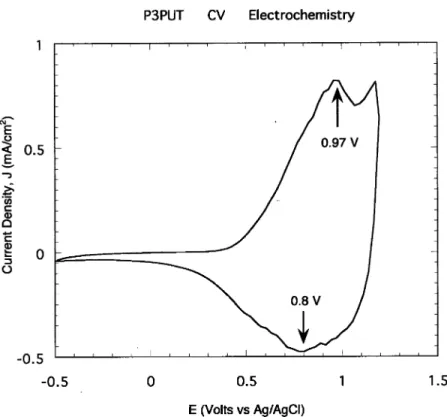
To replace the iodide redox mediator and the liquid electrolyte in a DSSC with a solid, one would have to determine, and control, the energetics of the hole conductor. Towards this goal, cyclic voltammograms (C2V) were recorded for the polythiophene polymers deposited on glass, and UV–visible spectroscopy was also performed (see Figs. 3 and 4). TheC2V plots determined the polymer’s oxidation potential, while the UV–visible work determined their band gaps. From theC2V
plots, the P3PUT, P4UBT and P3UBT deposited on conductive glass possess an oxidation potential,Eox;of approximately +1.1, 1.1 and 1.2 V [31], respectively, vs.
the normal hydrogen electrode (NHE). This corresponds to values of 5.6 and 5.7 eV vs. vacuum (0 V vs. NHE=4.5 eV vs. vacuum). For P3PUT, the C2V plot is displayed in Fig. 3, the UV–visible plot is displayed in Fig. 4 and theEoxenergy level is displayed in Fig. 5. The UV–visible results will be discussed shortly. The corresponding plots for P3UBT have been published previously [31]. As a comparison, theI3=I redox system, successfully used in the efficient liquid-based DSSCs, has a redox potential of 0.35 V vs. NHE, or 4.85 eV vs. vacuum [1, 27]. Also displayed in Fig. 5 are the Rudye’s energy levels [1, 27].
In addition to the establishment of the value forEox for the polythiophene hole conductors, the HOMO energy level, essentially the ionization potential (IP), of the p-type polymer material, can be estimated. It is determined from the onset potential, which itself is determined from the voltage at the intersection of the tangents drawn at the rising current and background charging current of theC2V plot. Using this method, previously applied to conductive polymers [32,33], the onset potential for the oxidation of the P3PUT was determined to be 0.72 V vs. NHE (0.5 V vs. Ag/ AgCl). Using an empirical relation utilized for conducting polymers [32, 33], the corresponding IP value is equal toqVonsetþ4:4 eV, whereVonsetis the onset potential vs. saturated calomel electrode (SCE). For P3PUT, this yields a position of the Fig. 3. Cyclic voltammogram (C2V) of the P3PUT polymer in 0.1 M TBATfB/acetonitrile vs. the Ag/ AgCl reference electrode. Oxidation and reduction peaks are indicated.
HOMO energy level of 4.9 eV vs. vacuum (recall that SCE is 0.24 V vs. NHE, and Ag/AgCl is 0.22 V vs. NHE). The HOMO energy, determined using the above method, for P3PUT is displayed in Fig. 5.
Although it acts as a redox mediator in the DSSC, it is yet unclear as to whether one should use the Eox; the HOMO level, or some other energy level for the polythiophene polymers in the DSSC. Unlike the dissolved iodide redox mediator in the liquid system, the polythiophenes are highly conjugated and are semiconducting solids. An alternative to the use of Eox or the HOMO energy level to describe the thermodynamics of the solar cell device is the Fermi level,Efp;of the polymer. For completeness, we herein report on contact potential difference measurements made by the Kelvin probe technique [27, 28] on P3PUT films deposited on SnO2:F coated glass. A work function value of 4.9770.05 eV in Argon was obtained in the dark; the work function determines the polymer’s Fermi level, Efp:This is very close to the value obtained for the HOMO level. Fig. 5 shows these values and the values from the literature for the TiO2conduction band (CB) andEfn in the dark [27].
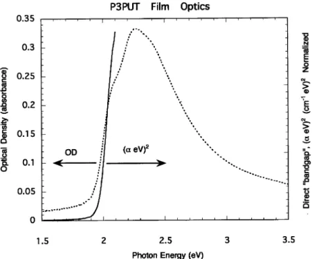
While the C2V and Kelvin probe measurements established the lower energy levels of the hole conductor, optical measurements can be used to estimate the upper energy level. The optical density of films on bare glass was plotted in accordance with the assumption that the polythiophene polymers posses a direct bandgap [24] (see Fig. 4. Optical density of a P3PUT film deposited on glass, and the corresponding analysis assuming a direct bandgap. This plot indicates a direct bandgap of 1.95 eV.
Fig. 4 for P3PUT). Given the straight line obtained in the plots, the assumption is valid, and these measurements yielded bandgaps of 1.9 and 2.0 eV for P3PUT and P3UBT [31], respectively. Combining this with the results reported above, one obtains the values 4.9 eV (HOMO), 4.97 (Efp) and 3.0 eV (LUMO) for P3PUT. For the P3UBT, the HOMO was likewise found to be 5.18 eV and the LUMO was found to be 3.18 eV. Using these values, energy band diagrams can be constructed to illustrate the thermodynamic mechanisms of how the polymers function in the device (see Fig. 5 for P3PUT). One finds from our C2V; UV–vis, and Kelvin Probe measurements that the P3PUT and P3UBT should both be capable of electron injection (dashed line in Fig. 5) into the TiO2, like the Rudye, and they should also
Fig. 5. Energy band diagram of the polythiophene P3PUT together with the Rudye and TiO2[1, 27, 28].
This was constructed with the values from theC2V;Kelvin probe, and spectroscopic measurements. The Fermi levels in the dark for the TiO2and polymer,EfnandEfp;respectively, are also shown. As a voltage
develops across the cell (e.g. under illumination) Efn and Efp are shifted upwards and downwards,
function as efficient hole conductors when used together with the Ru dye. In this regard, the energy band diagram and HOMO and LUMO values, the P4UBT is similar to the two other polythiophenes studied.
Femtosecond dynamics studies were conducted on a THF solution of the polymers. A typical transient absorption plot (at 790 nm) displayed a decay constant of 200–250 ps from a simple exponential fit to the data. The values for thin films of the same materials are expected to produce similar results [25]. Based on prior work, this excited state lifetime is sufficient for charge carrier injection [26] and efficient DSSC operation if the polymers were employed as a sensitizer. It should be noted that measurements were also attempted on composite systems consisting of TiO2 nanoparticles and the polythiophene polymers in solution. In contrast to dye-based systems previously studied [26], the polymers adhered to the TiO2only weakly, and thus the output signal consisted of both free and TiO2 associated molecules. Measurements of this type are difficult to interpret and may be reported in a future publication.
We have synthesized non-porous TiO2thin films for use in our solar cell devices via spray pyrolysis [29] and also via a sol–gel technique [30]. It was essential to have TiO2films that would block the passage of the hole conductor to the SnO2:F glass substrate, thus preventing short circuits. One must also anneal the TiO2 films at 4501C (30 min in air) prior to applying the dye in order to obtain reproducible devices. This must be done before spin coating the polymer to drive off any adsorbed species on the TiO2surface that may interfere with charge transfer.
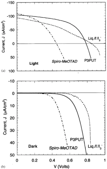
We have utilized the dense TiO2 and the polythiophene polymers to fabricate solid-state DSSCs (see Fig. 1b). Fig. 6 shows a comparison of the J2V
characteristics for three DSSCs utilizing the P3PUT, the liquid electrolyte (a
I=I
3 mediator), and the Spiro-MeOTAD [3] hole conductor. Rectifying behavior was observed, together with a strong photovoltaic effect under illumination. Fig. 7 shows the results of varying the light intensity on the P3PUT device in Fig. 6. From this, an extrapolated ‘‘dark’’ saturation value of approximately 1 nA/cm2 is obtained. This exceptionally low value, together with dark and light J2V
characteristics, indicate excellent junction properties.
All the devices produced exceptional results given the fact that only a single monolayer of Rudye and a thin (ca. 30 nm) non-porous layer of TiO2was utilized. For the DSSCs displayed in Fig. 6, we have obtained short-circuit currents,JSC;for all three hole conductors of approximately 90–100mA/cm2for measurements outside or under AM1.5 simulated illumination. Within the limits of our accuracy and reproducibility,710mA/cm2, all devices possessed identicalJSCvalues. Open-circuit voltageVOCvalues ranged from 0.45 V for the Spiro-MeOTAD, 0.84 V for the liquid junction control cell, and 0.8 V for the P3PUT-based device. The fill factor (FF) or ratio of the maximum power point to the product of the open-circuit voltage and short-circuit current, was 0.41, 0.36, and 0.53 for the Spiro-MeOTAD, liquid junction cell, and P3PUT, respectively. All three devices behave like a diode that does not obey the principle of superposition of the dark characteristics withJSC[34]. TheJ2V characteristics of the polythiophene-based device are in agreement with the energetics of the components reported in Fig. 5. Noteworthy is that the omission
of the Ru dye for devices utilizing the P3UBT or P4UBT hole conductors produced solar cells that behaved quite similarly (VOC¼0:8 VJSC ¼80290mA/cm2, FF=0.4) to those with the Rudye and the alkyl polythiophene both present. This is similar to results reported previously [19]. In contrast, cells without Ru dye and utilizing the P3PUT alone exhibitedJSC values of only 30–40mA/cm2.
Fig. 6. Light (a) and dark (b) current voltage curves for completed solar cells made with three hole conductors (P3PUT, liquid electrolyte/I=I
3 mediator, and Spiro-MeOTAD), using the Ru N3 dye and
the dense (non-porous) TiO2layer. For the device configuration, see Fig. 1b. The current–voltage (J2V)
characteristics for the solar cell in the dark (lower curves), and AM1.5 illuminated (upper curves) are shown.
Using an input solar power (at AM1.5) of 100 mW/cm2, the maximum solar conversion efficiency for the DSSC P3PUT device was calculated from the product of the FF,VOC;andJSCas 0.04%. The efficiency of the devices is admittedly small, but this was not the focus of our study, rather it was the development of rational selection criteria and testing techniques for the replacement of the liquid-based electrolyte via a solid. The porous nanocrystalline TiO2 utilized in conventional DSSCs has a surface roughness of over 500–1000 times the physical surface area [1,17,37], and a power conversion efficiency of approximately 10%. Comparing Figs. 1a and b, our results (for a surface roughness of 1.0) can therefore serve as a reference for just one of these multiple layers.
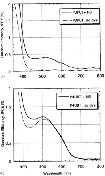
Fig. 8 shows the results of quantum efficiency measurements performed on the same devices as in Fig. 6. For dye sensitized cells, this external quantum efficiency is equal to the IPCE [1]. As can be seen, all of the devices performed similarly, exhibiting a UV response attributed to the TiO2, and a visible response peak at 530 nm due to the Ru dye’s absorption. Measurements made on liquid junction devices made without the (N3) Ru dye exhibited the response in the 300–400 nm range, but without the response in the visible portion of the spectrum. In Figs. 9a and b are shown the IPCE results from P3PUT- and P4UBT-based devices. The P3PUT cells exhibited quantum efficiency plots that indicate charge carrier generation from the TiO2 alone, but the P3PUT did not significantly sensitize the TiO2in the visible range (Fig. 9a). In contrast, those devices made without Ru dye with the alkyl polythiophenes P3UBT or P4UBT (Fig. 9b) exhibited a response from TiO2 as well as a response in the polymer’s optical absorption range. Those with P4UBT exhibited a peak response of 1.2% at 515 nm, while those for P3UBT exhibited a similar peak position but a response of only 0.5%. This is consistent with Fig. 7. Short-circuit current vs. open-circuit voltage for the P3PUT DSSC device as shown in Fig. 6. This indicates an extrapolated saturation ‘‘dark’’ current of approximately 1 nA/cm2.
previously reportedJ2Vresults [19] and the above-mentionedJ2Vresults for these devices. The IPCE values in the range 450–700 nm for the TiO2/Rudye/liquid junction device (shown in Fig. 8), and for the P3UBT and P4UBT devices without dye indicate that these polythiophenes could possess injection efficiencies similar to the RuN3 dye if only a monolayer is active in the process. This hypothesis will be examined shortly.
4. Discussion
It is significant that both P3UBT and P4UBT sensitize the TiO2in the absence of the Rudye, while the P3PUT does not sensitize TiO2. In other words, the P3PUT merely functions as the I=I3 mediator does, while the alkyl polythiophenes function as dyes and as hole conductors at the same time. From the results of the electrochemical studies and UV–visible spectra, one finds that the phosphonated and non-phosphonated polythiophenes do not appear to have significantly different energetics (HOMO and LUMO energy levels). Consequently, it would appear that they should all inject into the TiO2, yet only the P3UBT and P4UBT significantly inject. We have observed that both of these polythiophenes seem to adsorb to the TiO2, coloring it. Phosphonated Ru(bpy) dyes are found to attach strongly to the TiO2surface via the phosphonate group [35]. The qualitative difference in theJ2V and IPCE results between the P3UBT and P3PUT could be due to the orientation of the polymers on the TiO2surface. This could result in a difference in the kinetics of electron injection in the P3UBT and P4UBT compared to the P3PUT. This proposed Fig. 8. Quantum efficiency (IPCE) of the cells in Fig. 6. This is the number of output electrons (at short circuit) per input photon at a given wavelength. The response in the blue and UV regions is due to the TiO2
alone, while the peak at 530 nm is due to the Ru dye. The short-circuit currents,JSC;can be predicted from
mechanism can be confirmed in future studies. What is clear is that if one wishes to employ the polymer in the role of a hole conductor alone, not as a sensitizer, the properties exhibited by the P3PUT are the most desirable.
Given our results, one might be tempted to think that the P3UBT or P4UBT could be used to create efficient ‘‘organic solar cells’’ with the exclusion of the Ru dye (see Fig. 9. (a) (top) IPCE for the P3PUT solar cell made with and without the Ru N3 dye. As can be seen, the P3PUT polymer alone does not sensitize the TiO2, but it can act as a hole conductor for charge carriers
generated in the TiO2. Fig. 9b (bottom). IPCE for the P4UBT solar cell made with and without the Ru N3
dye. This shows that the P4UBT polymer does sensitize the TiO2. The P3UBT polymer shows a quite
Figs. 1b and 9b), but we propose that this approach may be problematic. In the case of the P3UBT or P4UBT solar cell without Ru dye, the devices resemble the so-called backwall illuminated heterojunction solar cell, examples of which are many thin film solar cells like CuInSe2or CdTe [34]. In this case of the polythiophene/TiO2 devices without Ru dye, absorption of photons produces excited states within the polymer layer. These are most likely bound electron–hole pairs, probably exitons and/or charged polarons that must subsequently diffuse to the polymer–TiO2 interface and/or the polymer–back contact interface to be separated and collected [36]. The exact nature of the photo-induced excited state is not, however, critical for the present discussion. What is important is that the IPCE, and therefore the photocurrent, is limited by each of the several processes that occur within this type of solar cell. Firstly, only part of the incident light is absorbed by the thin polymer layer in the device. Bound charge carriers must diffuse through the thickness of the polymer absorber and avoid recombination. Lastly, they must be separated, and the electron must be injected (or transferred) into the TiO2. The corresponding equation for the quantum efficiency is illustrated by
IPCE¼aðlÞZCZsepZinj; ð1bÞ
where aðlÞ is the fraction of the light which is absorbed, Zsep is the efficiency of polaron and/or exciton separation, andZinj is the efficiency of electron transfer into the TiO2. For the case of the ‘‘backwall illumination’’ heterojunction solar cell, the current collection quantum efficiency, ZC; is approximated by the well-known equation
IPCEpZCE 1
ð1þ1=aðlÞLÞ; ð1cÞ whereLis the diffusion length (e.g. for excitons and/or polarons), and is a measure of the length that an excited state can diffuse during its lifetime, before recombination. The term aðlÞ is the absorption coefficient of the light absorber (e.g. for P3UBT). From the UV–visible measurements, we determined aðlÞ ¼2:4105cm1
at the peak absorption wavelength for P3UBT films deposited on glass.
Even though Eq. (1c) is an approximation, encompassing only diffusion and transport, one may use it to gain useful insights into the limitations of the polythiophene solar cells made without dye (see Fig. 1b). One can connect the femtosecond dynamics of the polymer to the diffusion length mentioned above. From this, one can estimate the mobility of charge carriers in the polythiophene light absorber. The relationship between the excited state lifetime,t;and diffusion length is given [34] by Eq. (2)
L¼ ðDtÞ1=2; ð2Þ whereDis the diffusion constant given by the Einstein relation
D¼kTðK oÞm
where k is the Boltzman’s constant, q is the elemental charge, T is the absolute temperature, andmis the mobility of the charge carrier. One should again note that in the case of a typical solar cell,L;m andDrefer to either the free hole or the free electron, while in the present case they most likely refer to bound charges. From our femtosecond work, we obtained a t value of approximately 200 ps. In addition, substituted polythiophenes are known to have FET mobility values ranging from 105 to 0.1 cm2/V s [10]. The m values applicable to solar cells are expected to fall within the same range. For illustration, if we assume a value ofm¼3:5104cm2
/ V s, then, from the above equations, D¼9106cm2
/s, and L is approximately 0.4 nm, essentially a monolayer. AnZCvalue of approximately 1% is obtained from these values and Eq. (1c). Since polythiophene layers of several microns were utilized, the absorptivity, aðlÞ; approaches unity for wavelengths of 400–700 nm. Given our measured IPCE values of 0.5–1%, it is therefore likely thatZCis limiting the P3UBT/TiO2and P4UBT/TiO2solar cell’s performance rather than the other terms in Eq. (1b). Devices made with polythiophene films ranging in thickness from 0.4 nm to 4mm without dye did not generate significantly different JSC and IPCE outputs even though they absorbed different amounts of light. This would imply that only a monolayer of organic material is efficient for charge injection into TiO2, a conclusion that was well known at the time of the invention of the DSSC [1]. An efficient non-dye sensitized ‘‘organic solar cell’’ may thus be difficult to achieve unlessm;DandLcan be made larger than the values given above. This conclusion may also hold true for PPV-based PV devices and depends on them;DandLvalues for these materials. While it is certainly true for our homogenous polythiophenes, it is most likely also applicable even to the case of the bi-continous interpenetrating network approach [7–9] (compare Figs. 1a and b, respectively, with the dye omitted). On the other hand, utilizing a hole conductor with the samem;DandLvalues may be acceptable in the DSSC configuration (Fig. 1a). This is because the D value estimated above is not significantly different from the value for the diffusion of iodide ions in the liquid-based DSSC [37]. The IPCE values in the nanocrystalline DSSC are close to 100%, while the values for thick films of the absorbing polythiophenes are no higher than a few percent. If one utilizes porous TiO2, together with the Rudye and a relatively transparent hole conductor, as is done for the liquid-based DSSC (see Fig. 1a), then the device does not rely on the mobility in the light absorber. Instead, the IPCE is described by anL value of the composite material (TiO2+hole conductor) [27,37]. The diffusion coefficient, D; value of 106cm2/s found for liquid electrolytes results in efficient devices, and does not limit the performance, and so we conclude that the hole conductors characterized in the present study would be sufficient for the DSSC configuration if transparent versions could be placed within the porous structure shown in Fig. 1a. In this approach, the Rudye is the light absorber and the electron and hole transport is carried out by the TiO2 and thiophenes, respectively. This is the key difference between traditional heterojunction solar cells and the DSSC approach, where light absorption and charge transfer are themselves carried out by different materials.
Given the above analysis and discussion, our work therefore suggests some novel directions to explore for future studies on high-efficiency solid-state DSSCs. Rather
than focus on low-bandgap polymer and organic materials that can be used in place of the dye, as is now being extensively investigated [20,21,31,38,39], we suggest the use of transparent organic compounds that are employed to merely act as hole conductors in DSSCs. The use of this type of hole conductor would leave the Ru dye free to do its designed job of light absorption and charge injection into the TiO2. As the n value (see Fig. 2) and molecular weight of the polythiophene decreases, the polymer’s bandgap increases, making it transparent. One example known in the literature is the p-conjugated soluble thienylenevinylene dimer (TVD) shown in Fig. 10 [40]. This soluble solid has a redox potential of 1 V vs. SCE, and a bandgap of 3 eV, making it a possible p-type hole conductor that could be used in a nanocrystalline TiO2/RuDye/(TVD) configuration shown in Fig. 1a. It is likely that derivatives of the readily available thiophene-2-carboxylic acid would possess similar values to TVD. To allow electrical contact to the Ru dye, a suitable solid hole conductor should be amorphous as not to form crystallites in the pores of the nanoporous TiO2. Towards this end, side groups can be added to the hole conductor to sterically hinder the formation of an ordered lattice. One possible candidate compound is therefore 5-methylthiophene-2-carboxylic acid. Ionizable side groups can also be added to provide for charge compensation or charge screening [27,41,42]. Going beyond our specific case of thiophene-based hole conductors to a more general conclusion, we assert that our technique of using thin ‘‘flat’’ dense TiO2, can be employed as a tool to check one of the basic properties that is necessary for a solid-state DSSC. For example, high-surface area solid-state DSSCs have been fabricated using CuI as well as CuSCN [15–17]. Given that the AM1.5 solar-to-electric conversion efficiencies for these devices were over 1.5%, and that current densities of over 4 mA/cm2have been reported, these inorganic hole conductors are worthy of further study. While the conductivity estimates for the polythiophenes utilized in the present study lay in the range 107–109(Ocm)1, conductivities in excess of 102(Ocm)1 have been obtained for p-type CuI and CuSCN [43], indicating that they have higher hole mobilities. Application of the single-layer TiO2
Fig. 10. An example, suggested from our work, of a transparent thiophene compound that could be tested in the porous DSSC configuration of Fig. 1a. It is ap-conjugated thienylenevinylene dimer. This soluble solid has a redox potential of approximately 1 V vs. SCE, and a bandgap of 3 eV [40], making it a suitable p-type hole conductor that could be used in a nanocrystalline TiO2/Rudye/(TVD) device.
analysis, presented in the present study, to these materials could result in a convenient technique to check various dyes in combination with CuI, CuSCN (or other hole conductors). These inorganic materials can be deposited into the pores of the TiO2 via a solution-based technique, or electrochemically [16,43]. While there exists a need for future research to determine the best methods to deposit the hole conductors within the pores of the high-surface area TiO2(or, alternatively, ZnO), this goes beyond the scope of the present work. Instead, we propose that our technique can allow for a verification of one of the things necessary for the DSSC, so that parallel studies using high-surface area materials can proceed with confidence.
5. Conclusions
Our results demonstrate that a single TiO2–Rudye–polyalkylthiophene interface can function efficiently in charge transfer. Our studies demonstrated that the use of ‘‘flat,’’ dense TiO2 can be used to as a technique and tool to establish the effectiveness of hole transfer as compared to liquid junction devices. Both the polythiophenes and the Spiro-OMeTAD performed similar to the Iodide-based liquid electrolyte. If they do not perform as well as the liquid electrolyte using porous TiO2, then one must therefore look to hole conductor light absorption, pore filling, or charge compensation as the cause. Future studies can therefore utilize the types of hole conductors (thiophenes and Spiro-OMeTAD) described in this study, together with high-surface area TiO2, knowing that they are equivalent in one regard to the high-efficiency liquid electrolytes. We conclude that further work should therefore compare the performance of novel transparent hole conductors to that of liquid junctions formed on flat films, as well as on high-surface area materials. Over time, this approach can lead to gradually improving AM1.5 photocurrents and efficiencies in solid-state dye sensitized solar cells.
Acknowledgements
The authors would like to acknowledge the help and support of Michael Gratzel. of the EPFL. The authors would like to thank Dr. Brian O’Regan of EPFL and the Energy Center, Petten, Netherlands and David Cahen of the Weizmann Institute of Science, Rehovot, Israel for invaluable help. Support for this work was provided by the EPFL, the Deutsche Forschungsgemeinschaft (Geschaftszeichen SP607/1-1), as. well as the California Energy Commission PIER/EISG Grant 99-10. Support at Georgia Tech was provided by the US Department of Energy.
References
[1] M.K Nazerruddin, A. Kay, I. Rodicio, R. Humphry-Baker, E. Mueller, P. Liska, N. Vlachopoulos, M. Gratzel, J. Am. Chem. Soc. 115 (1993) 6382..
[2] M. Gratzel, Nature 414 (2001) 338..
[3] J. Kruger, R. Plass, L. Cevey, M. Piccirelli, M. Gr. atzel, Appl. Phys. Lett. 79 (2001) 2085.. [4] A.C. Arango, L. Johnson, V. Bliznyuk, Z. Schlesinger, S.A. Carter, H. Horhold, Adv. Mater. 12.
(2000) 1689.
[5] T.J. Savenije, J.M. Warman, A. Goossens, Chem. Phys. Lett. 287 (1998) 148.
[6] M. Granstrom, K. Petritsch, A.C. Arias, A. Lux, M.R. Andersonn, R.H. Friend, Nature 395 (1998). 257.
[7] J. Gao, G. Yu, A.J. Heeger, Adv. Mater. 10 (1998) 692.
[8] L. Schmidt-Mende, A. Fechtenkotter, K. M. ullen, E. Moons, R.H. Friend, J.D. MacKenzie, Science. 293 (2001) 1119.
[9] C.J. Brabec, N.S. Sariciftci, J.C. Hummelen, Adv. Funct. Mater. 11 (1) (2001) 15. [10] G. Horowitz, J. Mater. Chem. 9 (1999) 2021.
[11] M.A. Green, Adv. Mater. 13 (2001) 1019.
[12] G. Smestad, C. Bignozzi, R. Argazzi, Sol. Energy Mater. Sol. Cell 32 (1994) 259. [13] J. Turner, Science 285 (1999) 687.
[14] D. Pimentel, G. Rodrigues, T. Wang, R. Abrams, K. Goldberg, H. Staecker, E. Ma, L. Brueckner, L. Trovato, C. Chow, U. Govindarajulu, S. Boerke, Bio. Sci. 44 (1994) 536.
[15] K. Tennakone, G.R.R.A. Kumara, I.R.M. Kottegoda, K.G.U. Wijayantha, V.P.S. Perera, J. Phys. D 31 (1998) 1492.
[16] G.R.R.A. Kumara, A. Konno, G.K.R. Senadeera, P.V.V. Jayaweera, D.B.R.A. De Silva, K. Tennakone, Sol. Energy Mater. Sol. Cell 69 (2001) 195.
[17] B. O’Regan, D.T. Schwartz, S.M. Zakeeruddin, M. Gratzel, Adv. Mater. 12 (2000) 1263..
[18] W. Kubo, K. Murakoshi, T. Kitamura, Y. Wada, K. Hanabusa, H. Shira, S. Yanagida, Chem. Lett. Jpn. (1998) 1241.
[19] S. Spiekermann, G. Smestad, J. Kowalik, L.M. Tolbert, M. Gratzel, Synth. Metals 121 (2001) 1603.. [20] D. Gebeyehu, C.J. Brabec, F. Padinger, T. Fromherz, Synth. Metals 121 (2001) 1549.
[21] L. Sicot, C. Fiorini, A. Lorin, J.M. Nunzi, P. Raimond, C. Sentein, Synth. Metals 102 (1999) 991. [22] J. Kowalik, L. Tolbert, J. Chem. Soc. Chem. Com. (2000) 877.
[23] J. Kowalik, L.M. Tolbert, S. Narayan, A.S. Abhiraman, Macromolecules 34 (2001) 5471. [24] A. Chen, X. Wu, R.D. Rieke, J. Am. Chem. Soc. 117 (1995) 233.
[25] J.Z. Zhang, M.A. Kreger, G. Klaerner, M. Kretenschmidt, R.D. Miller, J.C. Scott, Femtosecond study of exciton dynamics in polyfluorene statistical co-polymers on solutions and thin films, Presented at Optical Probes of Conjugated Polymers, SPIE Proceedings, Vol. 3145, San Diego, CA, July 28–30, 1997, pp. 363–374.
[26] N.J. Cherepy, G.P. Smestad, M. Gratzel, J.Z. Zhang, J. Phys. Chem. B 101 (1997) 9342.. [27] D. Cahen, G. Hodes, M. Gratzel, J.F. Guillemoles, I. Riess, J. Phys. Chem. B. 104 (2000) 2053.. [28] F. Lenzmann, J. Kruger, S. Burnside, K. Brooks, M. Gr. atzel, D. Gal, S. R. uhle, D. Cahen, J. Phys..
Chem. B 105 (2001) 6347.
[29] L. Kavan, M. Gratzel, Electrochim. Acta 40 (1995) 643..
[30] M. Zaharescu, M. Crisan, I. Musevic, J. Sol–Gel Sci. Technol. 13 (1998) 769.
[31] C.D. Grant, A.M. Schwartzberg, G. Smestad, J. Kowalik, L.M. Tolbert, J. Zhang, J. Electroanal. Chem. 522 (2002) 40.
[32] R. Cervini, X-C. Li, G.W.C. Spencer, A.B. Holmes, S.C. Moratti, R.H. Friend, Synth. Metals 84 (1997) 359.
[33] Y. Li, Y. Cao, J. Gao, D. Wang, G. Yu, A.J. Heeger, Synth. Metals 99 (1999) 243. [34] A. Fahrenbrunch, R. Bube, Fundamentals of Solar Cells, Academic Press, New York, 1983. [35] P. Pechy, F. Rotinger, M.K. Nazeeruddin, O. Kohle, S.M. Zakeeruddin, R. Humphry-Baker, M.!
Gratzel, J. Chem. Soc. Chem. Com. (1995) 65..
[36] J. Simon, J.J. Andre, Molecular Semiconductors, Photoelectrical Properties and Solar Cells, Springer,! Berlin, 1985 (Chapter 1).
[37] J. Ferber, R. Stang, J. Luther, Sol. Energy Mater. Sol. Cell 53 (1998) 29.
[38] A. Dhanabalan, J.K. va Duren, R.A. van Hal, J.L.J. van Dongen, R.A.J. Janssen, Adv. Funct. Mater. 11 (2001) 255.
[39] L. Sicot, B. Geffroy, A. Lorin, P. Raimond, C. Sentein, J.-M. Nunzi, J. Appl. Phys. 90 (2001) 1047. [40] E.H. Elandalooussi, P. Fr"ere, P. Richomme, J. Orduna, J. Garin, J. Roncali, J. Amer. Chem. Soc. 119
(1997) 10774.
[41] F. Pichot, B. Gregg, J. Phys. Chem. B 104 (2000) 6.
[42] M. Turrio’n, B. Macht, H. Tributsch, P. Salvador, J. Phys. Chem. B 105 (2001) 9732.

![Fig. 2. Polythiophene polymers: poly[3-(11 diethylphosphorylundecyl) thiophene], P3PUT, poly(4- poly(4-undecyl-2,2 0 -bithiophene), P4UBT, or Poly(3-undecyl-2,2 0 -bithiophene), P3UBT utilized in the present study](https://thumb-us.123doks.com/thumbv2/123dok_us/1425446.2690792/5.702.128.573.116.416/polythiophene-polymers-diethylphosphorylundecyl-thiophene-undecyl-bithiophene-bithiophene-utilized.webp)
![Fig. 4 for P3PUT). Given the straight line obtained in the plots, the assumption is valid, and these measurements yielded bandgaps of 1.9 and 2.0 eV for P3PUT and P3UBT [31], respectively](https://thumb-us.123doks.com/thumbv2/123dok_us/1425446.2690792/10.702.134.564.122.607/given-straight-obtained-assumption-measurements-yielded-bandgaps-respectively.webp)