DETECTION AND TREATMENT OF THE SELF_CROSS IN
THE SHRINK PROCESSES OF PARAMETRIC ACTIVE
CONTOUR MODEL
1LIU HONGSHEN,2WANG NAN,3RUAN YUE
1
Prof., School of Computer Science,Anhui University of Technology,Ma’anshan Anhui,243002
2
Master Degree Candidate, School of Computer Science,Anhui University of Technology,Ma’anshan Anhui,243002
3
Assoc. Prof., School of Computer Science,Anhui University of Technology,Ma’anshan Anhui,243002 E-mail: [email protected],[email protected],[email protected]
ABSTRACT
The research object of this paper is the self_crosses of contour in parameter active contour model with shrink strategy (PACMS). For studying the object, parameter active contour model is improved to rapidly converge and reduce number of the self_crosses of contour. The concept of self_cross in PACMS is introduced and the influence of it on the evolution of PACMS is presented. With the improved model, the existence of self_cross in PACMS is shown. The treatments of self_cross on contours in the current literatures are analyzed. A model of describing the self_crosses is set up and an improved method of detecting and treating the self_crosses in PACMS is put forward. The experiment results of the new method are given and the comparison among the new method and other methods of detecting and treating the self_crosses are made. The result shows that the new method is more efficient than the other method of detecting self_crosses on contours.
Keywords:Parametric Active Contour Model, Parameter Active Contour Model With Shrink Strategy, The Self_Cross Of Contour, Detection, Treatment
1. INTRODUCTION
Parametric active contour model[1] (also known as snake,PACM) is the primary method of segmenting images and tracking videos. Its shortcomings are that the contour is hard to reach the depression area of the objects in images and the initial contour is required near to the objects as possible. These limit its applications. Because of those, many researchers have done some works to improve PACM and obtained some meaningful results[2-10].These works promote the application of
parts of objects. If the restriction is eliminated completely, the contours generate more much self_crosses in the evolution. That implied that the influences of tension and curvature on the contours must be modified along with the evolution of contours by changing their weights. But it is difficult how to change their weights in order to make the influence in a moderate degree. If a contour is set randomly, there are self_crosses of the contour, which they are inevitable by modifying the weights of tension and curvature. The self_crosses must exist in the evolution of contours when multiple objects are segmented from images with PACM and the time when it appears is that time when many objects are segmented. So it is meaningful to study the self_crosses of contour in PACM[7-11].
For studying the self_crosses of contour, we present an improvement of PACM in Section 2, describe how the self_crosses generate in the shrinking progress of contours and they influence on their application in Section 3. Detection and treatment of self-crosses are described in Section 4.In Section 5,we present some results and some discussion of our algorithm
2. IMPROVEMENT ON PACM FOR
RESEARCHING THE SELF_CROSSES OF CONTOURS
In order to study the self_crosses of contours, PACM must be improved. The goal of improving PACM keeps the contour evolution inward and reduces the number of self_crosses as possible. The discrete evolution equation in PACM is shown as follows: ) 2 ) ( ) ( ( 2 1 )
( 1 12
2 1
int i = i vi −vi− + i vi− − vi+vi+
E α β
(i=0,1,2,….,n) (1)
The progress of iteration evolution makes the sum of the energy Eint (i) minimum. The first order
derivative of formula (1) is the elastic energy of contours and makes contours short. The second
derivative is the rigid energy and makes contours smooth. These two parts contain no directivity information and don’t keep contours evolution inward [5]. Distribution of a part of pixels around one contour is shown as figure 1 and the black pixels form a segment of the contour. If contours are defined as rings with the clockwise or anti- clockwise directivity, the inner positions of the contour in figure 1 are exactly the opposite when passing the segment in figure 1 on two different directions. If the segment is searched in the sequence a and the contour is of the clockwise, the pixels in the contour are left. If the segments are searched in the sequence b and the contour is of the clockwise, the pixels in the contour are right. For the parameter active model with shrink strategy (PACMS), the energy of pixels in the contour and outside the contour must be different to ensure shrinking in the evolution of the contour. But the pixel energy calculated with the formula (1) is same. So the improvement of PACM is that one direction coefficient C is added at second derivative and the energy formula improved is shown as follows:
) 2 ) ( ) ( ( 2 1 )
( 1 12
2 1
int i = i vi−vi− +c⋅ ivi− − vi+vi+
E α β
(i=0,1,2,….,n) (2)
Figure.2: Definition Of Directive Number
Value of C is -1 for pixels in contours and +1 outside contours. In greedy algorithm, the candidate pixel of the pixel researched is located in its 8-neighbourhood, in which some pixels is in contours and the other is outside contours. C of a pixel in the 8-neighbourhood is related with its position i, j and calculated by the searching path. The searching path is described by two parameters, which one is called in_edge directive number and another is called out_edge directive number .The directive number is defined in figure 2.Let r be in_edge directive number and k be out_edge directive number, C is presented as such:
)
,
(
r
k
c
ij
=
χ
r,k {0,1,2,3,4,5,{,7{∈r、k are determined by the quadrant which edges locate in and whether the absolute value of
i j i j
x
x
y
y
−
−
is greater than 1,which xi,yi , xj,yj are the
coordinates of two endpoints in the edge. For example, the quadrant which in_edge locates in
figure 2 is 1 and the absolute value of j i i j
x
x
y
y
−
−
ofin_edge is greater than 1, the quadrant which out_edge locates in figure 2 is 4 and the absolute
value of j i i j
x
x
y
y
−
−
of out_edge is also greater than
1, so those red pixels C are -1 and the other are +1(see fig.2).Weight α,β are separately set 2.0 and
0.{ in the later experiment. The result shows that direction coefficient C prevents contours evolution outside and along tangential direction, and indeed reduces the number of self_crosses in contours 3. GENERATION OF THE SELF_CROSSES
IN THE SHRINKING PROGRESS OF CONTOURS AND THEIR INFLUENCE ON APPLICATION
PACMS because the demand for the regular shape limits the arbitrary of initial contour. In order to keep the shape of area segmented same as the shape of objects; the high density of vertexes on contours is required.
a) a initial contour and one object
b)self_crosses caused by the shape irregularity
Figure.3: self_crosses caused by the shape
irregularity of contour
a) An initial contour and two objects
b) self_crosses by multiple objects in evolution
Figure.4: self_crosses of contours caused by the
distribution of data in an image
Self_crosses of contours affect the subsequent evolution of PACMS and cause the evolution of contours to expand (see fig.5).In figure 5, the vertexes of the contour in the dashed box will expand rather than shrink. This leads the evolution of PACMS never to end. So the self_cross problem must be studied[11-14].
Figure.5: Influence of the self_crosses on the
evolution of contours
4. DETECTION AND TREATMENT OF
THE SELF_CROSSES IN THE
EVOLUTIONOF PACMS
4.1 Detection of self_crosses in the evolution of PACMS
includes two steps: the first step looks for self_crosses and the second step locates the self_cross which is found[14].Now there have been three methods for detecting the self_crosses. The first method is based on T_Snake model[11].The second method is detecting the self_crosses of contours by linear interpolation and sorting[12].The third is based on modern differential geometry[14].These methods have some shortcomings. For example, the method based on T_Snake model can not detect all self_crosses and the self_crosses which their size are less the size of the grid in T_Snake model are not able to be found. The method based on T_Snake model can not obtained also the position of intersection. The second method determines the self_crosses of contours by calculating the coordinate of intersection in two lines, and is complicated and unnecessary. The third method detects self_crosses by calculating the turn number[14] and is sophisticated to treat when there is even number of self_crosses in contours.
The time of detecting the self_crosses is between two turns of evolution. Number of times which the detecting algorithm is executing is same as the number of evolution turns. So the efficiency of the detecting algorithm greatly affects the whole progress of evolution of PACMS and it is essential to design a high performance algorithm of detecting the self_crosses of contours. PACMS is used for segmenting images and tracking video by scanning the whole image area in the evolution of contours. The characteristic data of images are investigated and determined whether the contours reach to the edges of objects in the progress of scanning. The intersection of two disconnect edges in a contour predicates that there is no characteristic data in the area which the two edges have scanned and the area must not be focused. Therefore, the task of locating self_crosses determines which two edges happen on
intersection without calculating the coordinate of their intersection. The traditional method estimating intersection of two line segments is the projection method. This method determines intersection of two line segments by means of the overlap situation that the projections onto X and Y axis of two lines. The traditional method is simply and not efficient. The method of the cross product of vectors is efficient in detecting self_crosses of contours[15].Here an improvement method of the cross product of vectors is used to detect the self_crosses on contours. Let two edges be
2 1
p
p
andp
3p
4.We regard the two edges as two
vectors
p
1p
2 andp
3p
4 .Two new vectors3 1
p
p
andp
2p
4 are defined as follows (seefig.{);
Figure.6 :Intersection of two vectors
The intersection conditions of
p
1p
2andp
3p
4include:
(1)
3 1
p
p
andp
2p
4 locate on two sidesof
p
3p
4 ;the direction ofp
3p
4 ×p
1p
3 isopposite from the direction of
p
3p
4×p
2p
4,thatis,the signs of the cross product of
p
3p
4×p
1p
3and
p
3p
4×p
2p
4 are different.(2)
3 1
p
of
p
1p
2;the direction ofp
1p
2×p
1p
3 is oppositefrom the direction of
p
1p
2 ×p
2p
4 ,that is.,thesigns of the cross product of
p
1p
2×p
1p
3 and2 1
p
p
×p
2p
4 are different.Two vectors are collinear when the cross product of them is zero. Let the coordination of the point Pi
be(Xi,Yi). Let
F1=
p
3p
4×p
1p
3=(X4-X3)(Y3-Y1)-(Y4-Y3)(X3-X1)F2=
p
3p
4×p
2p
4=(X4-X3)(Y4-Y2)-(Y4-Y3)(X4-X2)F3=
p
1p
2×p
1p
3=(X2-X1)(Y3-Y1)-(Y2-Y1)(X3-X1)F4=
p
1p
2×p
2p
4=(X2-X1)(Y4-Y2)-(Y2-Y1)(X4-X2)The intersection condition of
p
1p
2andp
3p
4 isdescribed as follows:
F1·F2<0∧F3·F4≤0 or F1·F2≤0 F3·F4∧ <0 (3) 4.2 Treatment of self_cross in the evolution of PACMS
The self_cross must be treated on time after it is found, or else it affects the next turn of evolution in PACMS. The treatment ways of self_crosses are related to the reasons which cause the self_crosses. The self_cross caused by multiple objects is treated by splitting the original contour into two contours. The self_cross caused by the others reasons are treated by discarding the segment between the two intersecting edges. So the first step of treating self_crosses determines which reason causes the self_cross in the evolution of PACMS.
There is only a contour at the beginning of the evolution of PACMS and more sub contours will be generated along with the evolution of PACMS. These new contours may produce more sub
contours again. Some of these new contours may be preserved and the others may be discarded. The method distinguishing them must be researched. Let’s start with the easiest situation which one initial contour and one sub contour exist. In that situation, the judgment changes along with the evolution of PACMS: ①at the initial stage of evolution, which all vertexes of the contours are not on the edges of the objects and the self_crosses are caused by the shape irregularity or the high vertexes density of contours, the length of redundant part is much shorter than the segment preserved; ②in the middle and late stage of the evolution of PACMS, which some vertexes may be on the edges of the objects, if a vertex of contours is on the edges of objects, the segment of the vertex is preserved(see fig.7).The judgment of vertexes on the edges of objects is based on the characteristic data in the vertex Pimage. If Pimage of a
vertex is greater than a threshold value Plevel, the
vertex is on the edges of objects.
Figure.7:The segment discarded and the segment
preserved when happening on self_crosses
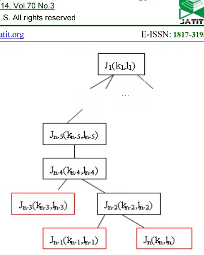
The general situation in the evolution of PACMS is that parent contour evolutes into multiple child contours (see fig.12 b)).The method of judging that a new contour is or is not preserved need be further studied in the general situation. This situation is described as follows:
moment of evolution be Ji(ki,li),iP[0,n].Here n is
number of self_crosses (number of pairs of
edges).ki and li respectively are the order number
of edges in self_crosses, i is the order number of
self_crosses and Ji is the name of self_cross. This
hints that M edges of the contour C are split into
2n segments. The treatment method can
distinguish which segment is the discarding
segment in the 2n segments. Assume that the
distribution of the n self_crosses and 2n segments
is shown as figure 8. The dotted lines indicate the
redundancy segments and the dashed lines indicate
the preserved segments.
Studying the 2n segments need search the
graphical structure data in fig.8 and the order of
studying the 2n segments must be determined. In
fact, the relations among these self_crosses or
segments are of tree structure characteristic.
Segments which are corresponding with the parent
nodes of the tree contain the segments
corresponding with the child nodes of the tree.
Tree structure of figure 8 is shown in figure
9.Integer pairs in brackets of figure 9 are the order
[image:7.595.303.505.81.333.2]numbers of edges happening on self_cross.
Figure.8:The n self_crosses situation of a contour
at moment of evolution
Figure 9 :Tree structure corresponding with
Figure 8
The tree is generated by the algorithm of
detecting self_crosses. Let the number of edges in
the initial contour be M. The detecting algorithm is
described with C language as follows:
for(i=0;i<M;i++)
for(j=i+2;j<M;j++)
{
Calculate F1,F2,F3,F4 of the edge pair of i and j;
If(formula (3)==true)
Save i and j
{
The self_cross information of contours can be
stored in a 2-dimensional array or a list. The root
node which is corresponding to the first segment
locates on the beginning of the array or list. The
order of items in the 2-dimensional array is same
as the order of self_crosses detected. If J1(k1,l1)is
the parent node of J2(k2,l2), J1(k1,l1)contains
J2(k2,l2),that is, k1≤ k2 and l1≥l2. If J1(k1,l1)and
J2(k2,l2) are leaf nodes at the same level,
[k1,l1]∩[k2,l2]=Φ, that is, [k1,l1] and [k2,l2] are not
overlap.
[image:7.595.90.279.496.565.2]whole tree and the traversal order is from the
beginning of the leaf nodes at lowest level. The
treatment procedure is that the leaf node is cutted,
judged and marked. While all leaf nodes of a
parent node have been treated and cut, the parent
node becomes a leaf node. This progress continues
until the root node is left. The treatment algorithm
is described as follows:
All items in the array storing the tree are
investigated according to the following way from
the beginning of the latest item:
1)pick out one node or one integer
pair(self_cross),Let the integer pair be (k,l).If it is
root node, The section investigated is
[l,M]∪[0,k],or else the section investigated is
[k,l].Go to next step;
2)examine all vertexes in the investigated section
as follows:
a) If the current vertex has been visited, the
flag of leaf node is set to false and go to 2);
b) Examine the characteristic data of vertexes
in the section.
b1) if the characteristic data Pimage of the
current vertex in the image is greater than
Plevel, then the segment is preserved and is
recorded, go to 5);
b2) go to 2)
3)If the flag of leaf node is true and |k-l|<<M-|k-l|,
then the segment between k and l is discarded and
make the discarding flag
4)If the flag of leaf node is false and the preserved
flag is false, the segment between k and l is
discarded and make the discarding flag except
those segments corresponding to the child nodes it
contains
5)if the discarding flag is true, a new contour
produces and all vertexes are marked
preserved(not including those segments
corresponding to the child nodes it contains);Or
else all vertexes are marked discarded (not
including those segments corresponding too the
child nodes it contains)
5. THE EXPERIMENTAL RESULTS AND THE DISCUSSION OF DETECTING AND
TREATING ALGORITHM OF
SELF_CROSSES
The above detecting and treating algorithm is
applied to figure 3 b) and figure 4 b) and the
results are shown in figure 10.Figure 10 shows that
the algorithm is effective for treating self_crosses.
The algorithm is used to segment multiple objects
and the result is shown in figure 11.Figure 11
illustrates the algorithm success in segmenting
multiple objects.
(a) The treating result of Figure.3b)
[image:8.595.330.497.335.678.2](b) The treating result of figure 4b)
Figure 10 the treating results of the algorithm
Figure 12 is same as figure 11 except the initial
contour. The initial contour in figure 12 is
shows that high density of vertexes very easily
lead to self_crosses of contour. In figure 12,one
initial contour produces four sub contours. Figure
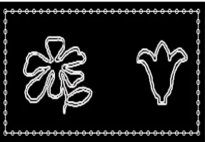
13 shows the treatment result for a actual image.
a) The original image and the initial contour
b) The self_cross in the evolution of the contour
c) The treating result of figure12 b)
Figure 11 treating self_cross and segmenting
multiple objects
a) The original image and the initial contour
b) The self_cross in the evolution of the contour
[image:9.595.87.238.191.290.2]c) The treating result of figure12 b)
Figure 12 the self_cross caused by the high vertex
density of contour
a) The original image and the initial contour
b) The self_cross in the evolution of the contour
[image:9.595.89.236.584.686.2]d) The final result
Figure 13 segmenting the actual image of chinese
characters
Here we make the comparison among the
traditional projection algorithm, the algorithms of
literature[15,16] and the above algorithm in detecting self_crosses. We respectively apply the traditional
projection algorithm, the algorithm of literature[15], the algorithm of literature [16] and the above algorithm in detecting self_crosses in Figure 11 b)
and Figure 12 b) and the result is shown in table
1.The Unit of data in table 1 is the time interval of
the counter in author’s pc and the data are the time
of detecting self_crosses, not including the treating
time. The data in table 1 shows that our algorithm
is most effective in detecting self_crosses.
Table 1 comparison of four algorithms in detecting
self_cross
No. L A1 A2 A3 A4
1 20 316782 17329 277836 16835
2 78 435637 285909 371072 283621
In Table 1,”No” column is No of the contour
studied, No 1 and No 2 are the contours in figure
11b) and figure 12b).”L” column is length of the
contour studied, ”Ai” column are the spending
time of the following algorithms:
A1: traditional project algorithm
A2: literature[13] algorithm
A3: literature[14] algorithm
A4: Our algorithm
As mentioned above, self_crosses of contours in PACMS appear inevitably and the study about them is of significance. The algorithm of detecting and treating self_crosses in contours makes the restriction condition of inner force in
PACMS much more relaxed, even unnecessary. It solves not only the problem of the convergence of the depressed area, but also eliminates the influence of self_crosses on further evolution of PACMS. Detection and treatment of self_crosses are meaningful for segmenting multiple objects and it is the key
which one contour becomes multiple
contours[10,11]. The study on self_crosses of
contours finds also some problems to be solved. The main problem is that treatment of self_crosses may cause the distribution density of vertexes in contours uneven. The problem will affects segmentation of multiple objects.
REFERENCES
[1] M. Kass , A. Witkin , D. Terzopoulos,
“Snake : Active contour models”,
International Journal Computer Vision ,
VOL.1,No.4,1988,pp.321-331
[2] L. D. Cohen, I. Cohen, “Finite element
methods for active contour models and
balloons for 2D and 3D images”,IEEE
Trans.PAMI, Vol.
15,No.11,1993,pp.1131-1147
[3] C. Xu , J. L. Prince, “Snakes , Shapes and
gradient vector flow”,IEEE Trans. Image
Processing , 1998 , 7 (3) : 359-3{9
[4] LI Pei hua, ZHANG Tian wen, “Review on
Active Contour Model (Snake Model)”.
Journal of Software, Vol.11,No.{,2000,pp.
751-757.
[5] Wang Yuanquan, Tang Min,”Research on
Boundary Concavities Segmentation via
Snake Models”. Journal of Computer
Research and Development,
Vol.42,No.7,2005,pp.1179-1184
[{] CHEN Bo,LAI Jian-huang.,”Active Contour
Journal of Image and Graphics,
Vol.12,No.1,2007,pp.11-19
[7] PAN Gai,GAO Li-qun,”Geodesic Active
Contour Model Combined with C-V and
GVF “,Journal of Northeastern
University(Natural Science),
Vol.34,No.2,2013,pp.1{{-170
[8] YU Xiao-sheng,WU Cheng-dong,”Gradient
Vector Flow Geodesic Active Contour Model
Based on Edge Preserving Diffusion”,
Journal of Northeastern University(Natural
Science), Vol.34,No.5,2013,pp.{42-{45
[9] Zhu Xiaoshu,Sun Quansen,”Adaptive active
contour model integrating global and local
image fitting energy”, Journal of Image and
Graphics , Vol.17,No.9,2012,pp.1109-1114
[10] GONG Xun,WANG Guo-Yin ,“Face
Segmentation Based on a Hybrid Energy
Based Active Contour Model”, Journal of
Software, Vol.24,No.3,2013,pp.{23-{38 [11]. T. McInerney and D. Terzopoulos,”T-snakes:
Topology adaptive snakes”,Medical Image
Analysis, Vol.4,No.2,2000,pp.73-91
[12]. L. Ji and H. Yan ,”Loop-free snakes for
highly irregular object shapes”,Pattern
Recognition Letters, Vol.23,No.5,2002,pp.
579-591 .
[13].Hua Fang, JeongWoo Kim,”A Fast Snake
Algorithm for Tracking Multiple Objects”,
Journal of Information Processing Systems,
Vol.7,No.3,2011,pp.519-529[14]. Nakhmani
A., Tannenbaum,”A. Self-Crossing Detection
and Location for Parametric Active
Contours”, IEEE Transactions on Image