VLSI ARCHITECTURE FOR LIFTING BASED DISCRETE
WAVELET TRANSFORM
DHANABAL R1, BHARATHI V2 , HYMA SOMAN3 , SAIRA SALIM 4
#1Assistant Professor (Senior Grade) ,VLSI Division,SENSE, VIT University, *2Assistant Professor,GGR College of Engineering ,Vellore,
#3,4
MTECH Students ,Sense department,VIT University, Vellore- 632014,Tamil Nadu, India E-mail: [email protected], [email protected], [email protected],[email protected]
ABSTRACT
A lifting based 2D DWT with efficient folded architecture and parallel scanning is being proposed. The architecture results in lesser hardware complexity and memory requirement due to multiplexing of 2 stages of lifting architecture. The 2D DWT architecture is realized by cascading two 2D processing elements. The coefficients for the lifting stage were chosen according with 9/7 filter. The 1D processing element has a column filter, transposing buffer and a row filter in it. The use of parallel scanning reduces the size of transposing buffer. Combining the intermediate results of row and column, the number of pipelining stages and registers are also reduced. The throughput obtained are 2 input and 2 output per cycle. The critical path for proposed architecture is one Tm.
Keywords: DWT, VLSI, Wavelet Transform, Architecture
1. INTRODUCTION
Discrete Wavelet Transform enables the decomposition of images into different sub bands both in frequency and time domain. Hence it enables multire solution and thereby giving high compression ratios. DWT has an upper hand over traditional Discrete Cosine Transform and thus its being widely used in signal processing and image processing areas.
The first generation DWT used convolution based techniques for image compression which had less quality [1][2]. The second generation DWT uses lifting schemes with different techniques for the same [3][4].The lifting scheme is preferred over convolution , because of it lesser memory requirement and lesser complexity. Several architectures were proposed with respect to lifting based scheme like efficient folded architecture, flipping architecture, pipelined architecture etc. The throughput of each architecture various and critical path also varies.
The efficient folded architecture EFA [5] is having lesser hardware complexity. But the critical path delay calculated is found to be Tm+Ta. Delay of multiplier is taken as Tm and
delay of adder is taken as Ta. Thus the critical path computation time is very high in EFA. Similarly the flipping structure also had longer computation time and with large temporal buffer. [6] Also the pipelined architecture gives high throughput of 2 input and 2 output enabling parallel processing .But the number of registers are high.[7]
2. LIFTING BASED DISCRETE WAVELET TRANSFORM
The lifting DWT consist of generally 3 stages- split, predict and update. During split stage the given data is divided to smaller levels O, E. We decompose the given data to 2 set such that the O component has some useful compared to E. In the predictor stage we L to predict H component based on correlation between the two. The polyphase matrix of DWT has upper and lower triangular matrices with diagonal matrix. The polyphase is matrix is shown as fig a
P(z) = Le(z) Lo(z)
He(z) Ho(z)
frequency components respectively. P(z) can be factorized to
P(z) =
1 0 1 t(z) -1 1/K
0 i=1
π
m
-
s(z)- 1 0 1 0 K
The lifting steps in detail are
a) Split step: The data is given into odd and even samples.
oio = x (2n+1) (1)
ei0 = x (2n) ( 2)
b) Predict and Update
I lifting stage: oi
1 = oi
o+ α (e i
0 + ei+1
0
) predict (3)
ei0 = ei1+ β (oi0 + oi+10) update (4)
II lifting stage:
oi1= oio+ γ (ei0 + ei+10) predict (5)
ei0 = ei1+ δ (oi0 + oi+10) update (6)
c) Scaling:
oi= 1/ K * oi2 (7)
ei= K * ei 2
(8)
3. PROPOSED LIFTING SCHEME.
In the proposed lifting architecture, the predict and update stages are merged in the 9/7 filter. 2D DWT is implemented using a coloumn
and row processing element. The concatenation of predict and update stages reduces the hardware requirement. The equations (4-6) and adjusted suitably to get the format
1/ α o(i) =x(2i +1) + x(2i) + x(2i-1) (9)
1/ β e(i) = x(2i) + o(i-2) + o(i) (10)
1/γ High(i) = 1/γ o(i) + e(i) +e(i+2) (11)
1/δ Low(i) = 1/δ e(i) +High(i)+High(i-2) (12)
Now considering equations 9 and 10 and doing associative rule
1/αβ e(i) = 1/αβ x(2i) + 1/α o(i) + 1/α o(i-2)
=[(1/αβ +1)x(2i) + 1/α 1) +
x(2i-2)] + [1/α x(2i+1) + x(2i) + x(2i+x(2i-2)].
Fig b.Block diagram of 2 D Lifting DWT
Here after one lifting stage, only low pass filter components are fed back and 2nd level compression is done. By increasing the number of feedback of low pass components we obtain multi resolution of image.
First we have a raw image which is divided into two parts using correlation technique into odd and even components. It is
then fed to coloumn processor first and after first lifting stage it is passed to transposing buffer and this performs shifting of image with requirement as of row processing element. After processing of 1st stag in row processor its fed to coloumn processor again to perform 2nd lifting stage followed by row filter. Here parallel processing was aimed at reducing the size of the transposing buffer helping in performing computation of 2 coefficients concurrently along row direction.
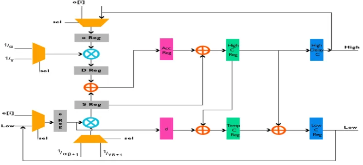
3.1 Coloumn Processing Element
The inputs to column processing element during the Ist stage are the odd and even signals and during II stage are High and low signals. These are being selected between a multiplexer enabling hardware reduction and effective implementation of 2 D coloumn processing element. The block diagram representation of 2 D coloumn processing element is shown in fig c
Fig c Block diagram of Coloumn Processing Element
The coefficients and inputs are selected using multiplxer by a select signal sel. The odd and even signals are stored in O reg and E reg respectively. To these value earlier calculated coefficients are multiplied and stored to D reg and S reg. after this 3 levels of pipeling is done. After computation we obtain high pass and low pass components of coloumn processing element .Its denoted as high C and Temp C and during
final pipelined stage its given to High delay C and Low C respectively. These are fed back to the input again to perform the 2nd lifting stage. Only low pass components are compressed to obtain a new image.
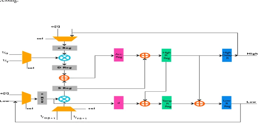
3.2 Row Processing Element
[image:3.612.137.510.398.568.2]element. It also process odd and even signals simultaneously and provide output .Thus we obtain 2 output at a time giving parallel processing.
Fig- d Block dig of Row processing Element
3.3 Transposing Buffer
Since parallel processing is done, the inputs have to switch between the modes needed as per requirement of processing elements. Thus in the proposed architecture, it uses a 2*2 transposing buffer which prevents the changing the size of it as per frame size as per earlier design.[8]
[image:4.612.105.523.140.341.2]4.PERFORMANCE ANALYSIS
Table 1 and Table 2 shows the comparison
of proposed DWT of 9/7 filter with various
architectures based on the resource
utilization. The proposed architecture has a
throughput of 2 input and 2 output with a
critical path of Tm ie one multiplier, with
reduction of resources cause of hardware
minimization of 2
ndlifting stage.
Table 1: 1D DWT core of 9/7 filter
Architecture Multiplie
r
Adder Register Critical
path
Throughput rate per cycle
Cell Based [10] 12 16 56 Tm 2 input 2 output
Parallel Scanning [8] 10 16 44 Tm 2 input 2ouput
Modified lifting [11] 6 8 42 Tm 1 input 1output
[image:4.612.84.544.575.688.2]Table 2: 2D DWT core of 9/7 filter
[image:5.612.88.537.102.628.2]
Figure e: Comaprison of various architectures in 1D DWT Core with respect to adders, mulripliers and registers
Figure f: Comaprison of various architectures in 2D DWT Core with respect to adders, mulripliers and registers
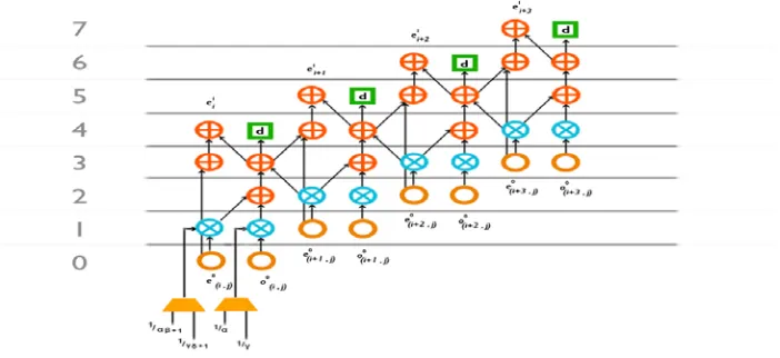
Fig - g DFG of Processing Element
Architecture Multiplier Adder Register Critical
path
Throughput rate per cycle
Shi [9] 2 4 10 Tm+Ta 2 input 2 output
Cell Based [10] 4 8 28 Tm 2 input 2 output
Parallel Scanning [8] 4 8 22 Tm 2 input 2ouput
Modified lifting [11] 2 4 20 T 1 input 1output
[image:5.612.132.483.544.705.2]5.CONCLUSION
In this paper we have developed and memory efficient and lesser hardware 2 D DWT with a critical path of Tm .The core of DWT has 2D row and coloumn processing elements and with 2*2 transposing buffer and temporal memory RAM. The transposing buffer size was reduced by using the parallel scanning method. The architecture was implemented using 45 nm Technology and coded using Verilog HDL and simulated using Cadence NC launch and synthesized in RTL compiler.
REFERENCES
[1] K. K. Parhi and T. Nishitani, “VLSI architecture for discrete wavelet transforms,”
IEEE Trans. Very Large Scale Integr. (VLSI) Syst., vol. 1,no. 2, pp. 191–202, Jun. 1993. [2] P.Wu and L. Chen, “An efficient architecture
for two-dimensional discrete wavelet transform,” IEEE Trans. Circuits Syst. Video
Technol., vol. 11,no. 4, pp. 536–545, Apr.
2001.
[3] W. Sweldens, “The new philosophy in biorthogonal wavelet constructions,”in Proc. SPIE., 1995, vol. 2569, pp. 68–79.
[4] I. Daubechies and W. Sweldens, “Factoring wavelet transform into lifting steps,” J. Fourier Anal. Appl., vol. 4, no. 3, pp. 245– 267, Mar. 1998.
[5] G. Shi, W. Liu, and L. Zhang, “An efficient folded architecture for liftingbased discrete wavelet transform,” IEEE Trans. Circuits
Syst. II, Exp. Briefs,vol.56,no.4,pp.290–
294Ap2009.
[6] C.-T. Huang, P.-C. Tseng, and L.-G. Chen, “Flipping structure: An efficient VLSI architecture for lifting-based discrete wavelet transform,”IEEE Trans. Signal Process., vol. 52, no. 4, pp. 1080–1089,Apr. 2004.
[7] Y. K. Lai, L. F. Chen, and Y. C. Shih, “A high-performance and memory-efficient VLSI architecture with parallel scanning method for 2-D lifting-based discrete wavelet transform,” IEEE Trans. Consum.
Electron.,vol. 55, no. 2, pp. 400–407, May
2009
[8] Yeong-Kang Lai, Member, IEEE, Lien-Fei Chen, Student Member, IEEE, and Yui-Chih Shih ,”A High-Performance and
Memory-Efficient VLSI Architecture with Parallel Scanning Method for 2-D Lifting-Based Discrete Wavelet Transform” IEEE Transactions on Consumer Electronics, Vol. 55, No. 2, MAY 2009.
[9] G. Shi, W. Liu, and L. Zhang, “An efficient folded architecture for lifting based discrete wavelet transform,” IEEE Trans. Circuits Syst. II, Exp. Briefs, vol. 56, no. 4, pp. 290– 294, Apr. 2009.
[10] Y.-H. Seo, and D.-W. Kim, “VLSI architecture of line-based lifting wavelet transform for motion JPEG2000,” IEEE J. Solid-State Circuits, vol. 42, no. 2, pp. 431-440, Feb. 2007.