Technology (IJRASET)
©IJRASET 2013: All Rights are Reserved
483
Large Deflection Analysis of Cantilever Beam
Using Artificial Neural Networking
Kumar Gaurav1, Sankha Bhaduri2, Arbind Kumar3 1,2,3
Mechanical Engineering Department, B.I.T., Mesra, Ranchi ,India
Abstract-- In this study the large deflection of the cantilever beam is analyzed under the action of point load at the free end of the beam. The large deflection of the cantilever beam causes the non linear behavior of beam. This non linearity is called the geometrical nonlinearity. The aim of this study is to predict the large deflection of a cantilever beam using Artificial Neural Networking (ANN). The experimentation of a cantilever beam is performed to collect the training data for the ANN. The experimental data is verified through the non linear finite element analysis in ANSYS software. It is observed that there is a very close agreement between the predicted data from ANN and the analytically found data from ANSYS.
Keywords-- Cantilever Beam, Large Deflection, Geometric Nonlinearity, Artificial Neural Network (ANN), ANSYS.
I. INTRODUCTION
The large deflection of a cantilever beam is one of the important research problems. The governing equation of large deflection of beam is difficult to solve due to the presence of a non-linear term. Therefore many attempts have been taken to solve this non linear problem using different analytical tools. In 2010 Li Chen [1] studied the large deflection of cantilever beam by using an integral approach. He followed an equation which is developed by Ang et al. By using this equation he obtained new equations of concentrated load, distributed load, combined load and changing cross section with concentrated load. In 2014 Pawar and Sawant [2] studied static analysis of cantilever beam experimentally by using Bernoulli-Euler relationship of uniform rectangular beam. He compared the numerical results with the ANSYS result. In 2002 Neipp et al. [3] studied the deflection of cantilever beam by analytically and numerically for both conditions a) Large and b) Small. He also followed Bernoulli-Euler relationship of uniform cross-section of beam and derived an equation of beam in non-linear terms for both conditions. He got the approximate same results. In 2014 Kimiaeifar et al. [4] studied analysis of large deflection of cantilever beam under point load and uniformly distributed load by obtaining governing equation for it and solved it by HAM (Homotopy Analysis Method). The result was compared with the software called as Finite Element Modeling (FEM). Both results are approximately equal. In 2002 Lee [5] studied analysis of large deflection of cantilever beam under combined loading by using Ludwick relation and Bernoulli-Euler bending moment relationship of uniform cross-section rectangular beam and obtained equation is solved by One-parameter shooting method. The result was compared with the result of ‘G.Lewis’ result. In 2005 Dado and Al-sadder [6] summarized several approaches which are used in large deflection problems. The first approach is based on elliptical integral formulation. The second approach is based on numerical integration with iterative shooting techniques. The third approach is based on incremental finite element method in connection with Newton-Rhapson iteration techniques for solving elastic problems. The fourth approach is based on incremental finite differences method in connection with Newton-Rhapson iteration techniques. The Artificial neural networking is one of the most important tools of this decade. ANN is very effective in the non linear problems. In this paper the large deflection of the beam is predicted using artificial neural networking. Experimentation is conducted to collect the data to train the network. The experimental result is verified with the help of ANSYS software.
A. Artificial Neural Network (ANN)
©IJRASET 2013: All Rights are Reserved
484
the weights on the connections between the input and the hidden units. The behavior of the output units depends on the activity of the hidden units and the weights between the hidden and output units. ANN has several advantages but one of the most recognized of these is the fact that it can actually learn from observing data sets. In this way, ANN is used as a random function approximation tool. These types of tools help estimate the most cost effective and ideal methods for arriving at solutions while defining computing functions or distributions. ANN is considered fairly simple mathematical models to enhance existing data analysis technologies.
B. ANSYS
ANSYS or Finite element analysis was first developed by R. Courant in 1943, who utilized the ritz method of numerical analysis and minimization of variational calculus to obtain approximate solutions to vibration systems. ANSYS is used to obtain the approximate solution to the boundary value problems for differential equations like forces, vibration, heat transfer, fluid dynamics, various electrical and magnetic phenomena and other physical effects. It is also referred as a Finite element method. The need of this method arises from the fact that for most practical engineering problems analytical solution does not exists. To obtain a solution, the engineer must make simplifying assumptions, reducing the problem to one that can be solved. Finite Element Analysis (FEA) subdivides an object into a large number of smaller, simpler parts or finite elements. The simple mathematical equations help to predict the behavior of each element. Finite elements are then assembled into a larger system of equations that models the entire problem. Subdivision of object into simpler element has several advantages: a) Accurate representation of complex geometry, b) Inclusion of dissimilar material properties, c) Easy representation of the total solution. The finite element method is one of the most powerful approaches for approximate solutions to a wide range of problems in mathematical physics.
II. ANALYSIS
A. Experimental
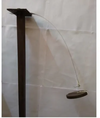
In the laboratory, experiment is designed to perform numerical methods present in this paper. Consider a cantilever beam of flexible steel of rectangular cross-section, fixed at one end and free at other end with different load applied. The beam is fixed to a vertical stand rod by using two nuts and bolts to provide better support. The experimental setup of the beam is shown in Fig. 2. The measurements of the beam are: length, L=0.400m, width, b=0.0245m, height, h=0.001m, weight, W=0.055kg. Moment of Inertia (M.I.), I=2.042x10⁻¹²m4. At the free end we applied different loads like 0.49N, 0.981N, 1.962N, 4.905N, 9.81N for experimental measurement. Assume young’s modulus of elasticity (typical value for steel) E=200x109N/m2.Due to the application of vertical load at the free end of the beam structure the beam will bend. The bending of the beam will be both along the horizontal and vertical directions. The deflections along both the horizontal and vertical directions are measured. The different parameters used in this experiment are listed in the Table 1 given below. The experimental results from the experiment are listed in Table 2.
TABLEI
DIFFERENTPARAMETERSOFTHEBEAM
S.No. Parameter Values
1 Length 0.400m
2 Width 0.0245m
3 Height 0.001m
4 Weight 0.055kg
5 M.I. 2.042x10⁻¹²m4
TABLEII
DEFLECTIONOFBEAM(EXPERIMENTAL)
S.No. Weight Δx Δy
1 Self weight 0 0.011
2 0.4905N 0.002 0.038
3 0.981N 0.007 0.062
4 1.962N 0.018 0.107
5 4.905N 0.066 0.200
Technology (IJRASET)
©IJRASET 2013: All Rights are Reserved
485
Figure 1: Experimental set-up when 500 gm weights applied.
B. Finite Element Analysis Of The Beam
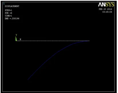
[image:4.612.141.478.78.478.2]To validate the experimental results the finite element analysis of the beam is done using ANSYS software. Ten element discretization of the steel cantilever beam is done in ANSYS using Beam 3 element. One end of the beam fixed end a point load is applied at the other end of the beam. The horizontal and vertical free end displacements of the beam are listed in Table 3. From Table 3 it is clear that there is a very close agreement between the experimental results and the ANSYS results. The deflected shape of the beam is shown in Fig. 3.
TABLE III
DEFLECTIONOFBEAM(ANSYS)
S.No. Weight Deflection %Error
Δx Δy Δx Δy
1 Self weight 0 0.011 0 0
2 0.4905N 0.002 0.036 0 5.27
3 0.981N 0.007 0.061 0 1.6
4 1.962N 0.017 0.105 5.6 1.87
5 4.905N 0.065 0.198 1.5 1
©IJRASET 2013: All Rights are Reserved
486
Figure 2: ANSYS deflection when 500gm weights applied
C. Artificial Neural Networking Prediction Of The Deflection
The experimental results of the beam are used to train the network in the ANN. Where six inputs were used for the training purpose. First create the table for both input and output in workspace window in MATALB. In input table, the data of all applied loads and in output table, the data of deflections for both δx, δy. For training select both the table from workspace window and train the network by using Levenberg-Marquardt method. Train the network until regression level come approx to 1. By generating Simulink diagram, feed the unknown value of load and get the approximate value of deflections. From ANN the free end displacement is predicted for the different loading where the loads are within the training range. One sample data is obtained for the load outside the training range also. The predicted values of the displacements are listed in the Table 4. The fem analysis of the beam is done to check the efficiency of the prediction of the ANN. From the table it is very clear that the prediction is very close to the ANSYS results.
Table IV
PREDICTION OF DEFLECTION
S.No. Weight ANSYS ANN % Error
δx Δy Δx δy Δx δy
1 0.75N 0.004 0.049 0.004 0.046 0 -6.52
2 1.5N 0.011 0.085 0.012 0.092 8.3 8
3 2.5N 0.024 0.1267 0.025 0.1307 2.82 3.06
4 3N 0.033 0.1448 0.035 0.1488 5.7 2.69
5 8.83N 0.1 0.2425 0.095 0.2252 -5.2 -7.68
Technology (IJRASET)
©IJRASET 2013: All Rights are Reserved
487
III. CONCLUSION
Artificial Neural Networking is very effective tool in case of non linear problems. As the large deflection of the cantilever beam problems are considered as the nonlinear problems so an attempt has been taken to predict the deflection of the beam using ANN. This method is very useful to analyze the deflection of the beam for any load if the network is trained for once. Therefore in this paper the non linear deflection of the beam is done using experimental analysis, fem analysis and ANN analysis.
REFRENCES
[1] Li Chen, “An integral approach for large deflection cantilever beams”, in International Journal of Non-linear Mechanics, vol. 45, pp. 301-305,2010.
[2] R.S. Pawar & S.H. Sawant, “Experimental static Analysis of a Cantilever Beam with Nonlinear Parameters”, International Journal of Engineering Sciences & Research Technology, ISSN: 2277-9655, Sept. 2014.
[3] Tarsico Belendez, Cristian Neipp & Augusto Belendez, “Large and Small deflections of cantilever beam”, European Journal of Physics, vol.23, pp. 371-379, May2002.
[4] A. Kimiaeifar, N. Tolou, A. Barari & J.L. Herder, “Large deflection analysis of cantilever beam under end point and distributed loads”, Journal of Chinese Institute of Engineers, vol.37, pp. 438-445, 2014.
[5] Kyungwoo Lee, “Large deflections of cantilever beams of non-linear elastic material under a combined loading”, International Journal of Non-linear Mechanics, vol. 37, pp. 439-443, 2002.