Technology (IJRASET)
©IJRASET 2015: All Rights are Reserved
152
Fuzzy Logic Controller Based Speed Analysis and
Control of DC Shunt Motor
Bhaskar Roy1, Shilpi Sisodiya2
1
M.Tech Student , 2Assistant professor, Department of Electrical Engineering, MPCT Gwalior (India)
Abstract: In this paper, various speed control techniques for a dc shunt motor namely conventional PID controller and fuzzy logic controller, using a PID controller and Fuzzy Logic Controller have been discussed and a comparative analysis between them. When compared to conventional PID controller then we found that Fuzzy controller provides better speed. Finally, the result shows that the fuzzy logic approach has minimum transient response; fuzzy logic controller is more effectiveness and better efficiency than conventional PID controller. The DC shunt motor models have been developed using SIMULINK MATLAB and the comparative analysis is based on the speed responses obtained by simulation of the DC shunt motor models. Keywords- Speed control, DC shunt motor, PID Controllers Design, Simulation, fuzzy logic controller.
I. INTRODUCTION
DC motor is a power actuator which converts electrical energy into mechanical energy. DC motor is used in applications where wide speed ranges are required. The greatest advantage of dc motors is speed control. The term speed control stands for intentional change of the drive speed to a value required for performing the specific work process. Speed control is either done manually by the operator or by means of some automatic control device. DC motors are most suitable for wide range speed control and are therefore used in many adjustable speed drives [1]. The speed torque characteristics of DC motors are much better to that of AC motors. Also DC motors provide excellent control of speed for acceleration and deceleration. DC motors have a long practice of use as adjustable speed machines and a wide range of options have evolved. In these applications, the motor should be accurately controlled to give the desired performance. The controllers of the speed that are conceived for objective to control the speed of DC motor to execute many tasks [2].Speed control means intentional change of the drive speed to a value required for performing the specific work process. Speed control is a different concept from speed regulation where there is natural change in speed due change in load on the shaft. Speed control is either done manually by the operator or by means of some automatic control device. One of the important features of DC motor is that its speed can be controlled with relative ease [3]. The main advantage of DC motors is the speed control facility. The term speed control stands for intentional speed variation done by automatic controllers or by manual means. For further improvement of the speed response characteristics of the DC motor, another controller called Fuzzy Logic Controller (FLC) has been developed. Fuzzy logic control is a linguistic control algorithm which uses general statements instead of the mathematical equations to define the control scheme of the responses. Due to this technique, a wide range of values are included in the set which leads to better rise time, less speed fluctuations and overshoots. With fuzzy logic controller, manual tuning is eliminated and intelligent tuning takes the centre stage with satisfactory performance. There are several conventional types such as Proportional (P), Proportional Integral (PI), Proportional derivative (PD).Proportional Integral derivative controller (PID) [4] and Fuzzy Logic Controller (FLC) [5][6]. This paper mainly focuses on the performance evaluation of DC motor using, Proportional Integral derivative controller (PID) and Fuzzy Logic Controller (FLC).The simulation results are presented to demonstrate the effectiveness of this controller and compared with PID controller using MATLAB / SIMULINK.
II. INTRODUCTIONOFDCSHUNTMOTOR
©IJRASET 2015: All Rights are Reserved
153
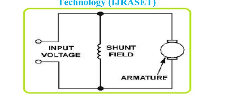
Fig 1 diagram of Shunt DC Motor
This type of motor runs practically constant speed, regardless of the load. It is the type generally used in commercial practice and is usually recommended where starting conditions are not usually severs. Speed of the shunt-wound motors may be regulated in two ways: first, by inserting resistance in series with the armature, thus decreasing speed: and second, by inserting resistance in the field circuit, the speed will vary with each change in load: in the latter, the speeds are practically constant for any setting of the controller. A high-quality speed control system makes the DC motor suitable for the applications in which changeable speed variation, frequent starting, proper speed regulation, braking and reversing are required.
III.MODELINGOFDCSHUNTMOTOR
DC shunt motors have the field coil in parallel (shunt) with the armature show in the fig 1. The current in the field coil and the armature are independent of one another. As a result, these motors have excellent speed control [8]. Hence DC shunt motors are typically used applications that require five or more horse power. The equations describing the dynamic behavior of the DC motor are given by the following equations;
A. Numerical Values
The DC motor under study has the following specifications and parameters. 1) Specifications: 2hp, 230 volts, 8.5 amperes, 1500rpm
2) Parameters: Ra=0.45 ohm, La=0.035 H, Kb=0.5 volt/(rad/sec), J=0.022Kg-m2/rad, B=0.2*10^-3N-/(rad/sec).
= +
+
Because the back EMF eb is proportional to speed ω directly, then
= =
=
+
( )
( )= ( + )( + ) + +
The overall transfer function of the system is given below,
( ) ( )=
0.5
0.0077 + 0.09007 + 0.25018
IV.PIDCONTROLLERSDESIGN
Technology (IJRASET)
[image:4.612.173.447.82.182.2]©IJRASET 2015: All Rights are Reserved
154
Fig 2: Simulation Model of PID Controller
PID controller can be investigated under three main categories. Each controller has different properties in terms of controlling the whole system. In proportional control, adjustments are based on the current difference between the actual and desired speed. In integral control, adjustments are based on recent error in derivative control; adjustments are based on the rate of change of errors [9].
V. INTRODUCTIONOFFUZZY-LOGIC
The fuzzy logic foundation is based on the simulation of people’s opinions and perceptions to control any system. One of the methods to simplify complex systems is to tolerate to imprecision, vagueness and uncertainty up to some extent. An expert operator develops flexible control mechanism using words like “suitable, not very suitable, high, little high much and far too much that are frequently used words in people’s life. Fuzzy logic control is constructed on these logical relationships. Fuzzy sets are used to show linguistic variables. Fuzzy Sets Theory is first introduced in 1965 by Zadeh to express and process fuzzy knowledge [10].Fuzzy control systems are knowledge-based or rule-based systems. The heart of a fuzzy system is a knowledge base consisting of the so-called fuzzy IF-THEN rules. A fuzzy IF-THEN rule is an IF-THEN statement in which some words are characterized by continuous membership functions [11]. The objective is to implement FLC for controlling the speed of a dc motor. The change of speed of error plays important role to define controller input. Consequently FLC uses error (e) and change in error (ce) for linguistic variables which are generated from control rules. The output variable is the change in control variable of the motor drive. FLC (fuzzy logic control) control has proven effective for complex non linear and imprecisely defined process for which standard model based control techniques are impractical. Fuzzy logic deals with the problems that have vagueness uncertainty and membership function between 0 to 1. I.e. if the reliable expert knowledge is not available or if control system is too complex to derive the required decision rules, then some efforts have been made to solve these problems and simplicity the task of tuning parameters and developing rules for the controller [12].
VI.COMPONENTSOFFUZZYLOGICCONTROLLER
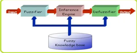
The inputs to a Fuzzy Logic Controller are the processed with the help of linguistic variableswhich in turn are defined with the aid of membership functions. The membership functions are chosen in such a manner that they cover the whole of the universe of discourse. To avoid anydiscontinuity with respect to minor changes in the inputs, the adjacent fuzzy sets must overlapeach other [13][14]. Because of a small time constant in Fuzzy Logic Controllers, this criterion is veryimportant in the design of the same [15]. There are basically three essential segments in Fuzzy Logic Controller viz.
(1) Fuzzification (2) Inference (3)Defuzzification
[image:4.612.188.425.600.692.2]©IJRASET 2015: All Rights are Reserved
155
[image:5.612.156.462.138.275.2]to a fuzzy quantity, fig 3 Basic structure of fuzzy logic system. The output of a fuzzy process can be the logical union of two or more fuzzy membership functions defined on the universe of discourse of the output variables.in this paper use of fuzzy logic FIS editor with 9 rule bases and Rule viewer of fuzzy controller are show in the fig 4 and fig 5.
[image:5.612.156.461.531.686.2]Fig. 4 FIS editor of fuzzy controller with 9 rule base
Fig. 5 Rule viewer of fuzzy controller with 9 rule base
VII. SIMULATIONRESULTSANDDISCUSSIONANALYSIS
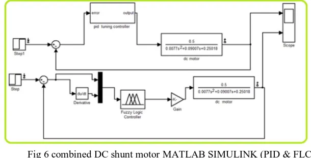
The combined DC shunt motor MATLAB SIMULINK model of system under study with PID controller and fuzzy logic controller is shown in Fig 6.
Fig 6 combined DC shunt motor MATLAB SIMULINK (PID & FLC)
Technology (IJRASET)
©IJRASET 2015: All Rights are Reserved
156
[image:6.612.158.458.100.230.2]output response show in the fig 7 and fuzzy logic controller output response show in the fig 8.
Fig 7 PID controller output response show
Fig 8 PID controller output response show
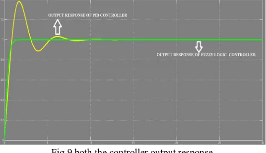
[image:6.612.162.455.242.418.2]Comparison between both controllers gives the different output response. The Fig. 9 shows that both controllers have own performance to analyze. The FLC controller has not percentage overshoot but the PID controller has percentage overshoot. The settling time is the time that taken to reach from steady state, for this output response the FLC is faster than PID controller.
Fig 9 both the controller output response
VIII. CONCLUSION
[image:6.612.173.441.483.637.2]©IJRASET 2015: All Rights are Reserved
157
[1] Suranjana Bharadwaj, “Comparative Analysis of Speed Control Techniques of DC Motors with Matlab” International Journal of Engineering Research & Technology (IJERT).Vol. 4 Issue 05, May-2015.
[2] Mr. R. B. Nimbalkar, “A Review on Significance of PID Controller for Speed Control of DC Motor” International Journal on Recent and Innovation Trends in Computing and Communication ISSN: 2321-8169, Volume: 3 Issue: 4, April 2015, 2080 – 2082.
[3] Gaurav Kumar Mishra;2Dr A.K Pandey;3Avinash Maurya, “Combined Armature and Field Speed Control of DC Motor For Efficiency Enhancement” SSRG International Journal of Electrical and Electronics Engineering (SSRG-IJEEE) – volume 1 Issue 6 -August 2014.
[4] K.H. Ang, G. Chong and Y. Li, “PID control system analysis, design and technology,” IEEE transaction on Control System Technology, Vol.13, No.4, 2005, pp. 559-576
[5] Gauri V. Deshpande1 and S.S.Sankeshwari2, “Speed Control Of Induction Motors Using Hybrid Pi Plus Fuzzy Controller” International Journal of Advances in Engineering & Technology, Nov. 2013.
[6] Niraj Kumar Shukla and Dr. S K Sinha, “Fuzzy and PI Controller Based Performance Evaluation of Separately Excited DC Motor” International Journal of Emerging Trends in Electrical and Electronics (IJETEE) Vol. 2, Issue. 1, April-2013.
[7] Neenu Thomas, Dr. P. Poongodi, “Position Control of DC Motor Using Genetic Algorithm Based PID Controller” Proceedings of the World Congress on Engineering 2009 Vol II WCE 2009, July 1 - 3, 2009, London, U.K.
[8] Megha Jaiswal , Mohna Phadnis (H.O.D. EX), “Speed Control of DC Motor Using Genetic Algorithm Based PID Controller” International Journal of Advanced Research in Computer Science and Software Engineering, Volume 3, Issue 7, July 2013.
[9] S.W. Lee,S.Kim & Y.Park,(1998) ,“Fuzzy Pre-Compensated PI Controller For A Variable Capacity Heat Pump”, In proceedings of the IEEE Conference on control Applications, pp953-957.
[10] Mohammed Shoeb Mohiuddin, “Comparative study of PID and Fuzzy tuned PID controller for speed control of DC motor “international journal of innovations in engineering and technology, volume 2 Issue 4 -August 2013.
[11] Osama Omer Adam Mohammed1, Dr. Awadalla Taifor Ali 2, “Comparative Study of PID and Fuzzy Controllers for Speed Control of DC Motor” International Journal of Innovative Research in Science,Engineering and Technology,Vol. 3, Issue 9, September 2014.
[12] Mr. Tushar Upalanchiwar , Prof.A.V.Sakhare, “Design and implementation of the fuzzy PID controller using MATLAB/SIMULINK model” International Journal of Research in Computer and Communication Technology, Vol 3, Issue 3, March- 2014.
[13] Nur Azliza Ali, “Fuzzy logic controller for controlling DC motor speedusing MATLAB applications”.
[14] Manafeddin Namazov and Onur Basturk, “DC motor position control using fuzzy proportional-derivative controllers with different defuzzification methods,” Turkish Journal of Fuzzy Systems (e-ISSN: 1309–1190), Vol.1, No.1, pp. 36-54, 2010.