5
IV
April 2017
Technology (IJRASET)
©IJRASET: All Rights are Reserved
1521
Analysis of Multicylinder Petrol Engine Intake
Manifold Flow using CFD
Sasikumar. A1, V. Sugan2
1
PG Scholar, 2AP, Department of Mechanical Engineering Mahendra Engineering College Namakkal, TN, India
Abstract: Multicylinder engines are most widely used in high sector cars so as to get comfort. The power balancing of multicylinder engines are very high but the fuel efficiency is not in the expected range. This is due to the location of carburetor, length and diameter of intake manifold runners, geometry of pipe junction, design of manifold itself and etc. Now days there are advanced technologies like Multi Port Fuel Injection (MPFI) to overcome this problems but some attention to be given to the carburetor type engine. Design and operational variables of inlet system are decisive factor to determine engine performance. The engine overall performance can be obtained by proper design of the engine inlet system. The various aspects of the intake manifold design that affect the engine performance are to be analyzed and optimum parameters are found out using Design of Experiments (DOE). The parameters are modeled and computer flow model of intake manifold has been developed using Computation Fluid Dynamics (CFD) code. The parameters are analyzed and the optimum parameter has chosen using the design of experiments. Finally evaluate the optimum parameter result to the actual dimension results. Flow inside the intake manifold is assumed to be two-dimensional, unsteady, compressible and turbulent. Computer simulation results are presented in the form of velocity and pressure. The simulation results are comparing to the experimental data
Keywords: Ceramic coating, ANSYS, Computation Fluid Dynamics , Design of Experiments
I. INTRODUCTION
Multi-cylinder engines are required to run smoothly. Smooth operation can only occur when each combustion chamber produces the same combustion pressure as every other chamber in that same engine. To do this, each cylinder must receive a charge exactly like the charge going into the other cylinders in quality and quantity. The air coming into an engine will flow through carburetor. The carburetor is a device that provides the charge quality by mixing fuel into the incoming air in the correct proportions. The intake manifold directs an equal quantity of the mixture charge to the inlet valve. Each intake valve must be timed the same as the others to allow an equal quantity of the mixture of the charge to enter each combustion chamber. When all these requirements are met the pressure in the combustion chamber will be equal. It is unfortunate that an engine has not, as yet, been meeting these ideal requirements under all operating conditions. For minimum manufacturing cost, tolerance must be quite large so the valve and the ignition timing between cylinders are not exactly same. Flow analysis of the engine inlet manifold is analyzed using computational fluid dynamics commercially available software. From the intake manifold model, the flow characteristics inside an intake manifold can be analyzed and the variables that affect the engine performance of an engine are investigated. The parameters are chosen and which parameter affects mostly to the performance of the engine using the design of experiments. Manifold geometry and the manifold pressure is the primary interest of this project. The aspects of the inlet manifold design that affect engine performance are, length and diameter of the inlet runners, length and diameter of the outlet runners and curvature radius, to varying these parameters and to find the optimum parameter. In the optimum configurations are modeled and analyze is to be done using computational fluid dynamics code.
II. COMPUTATIONAL FLUID DYNAMICS
Technology (IJRASET)
©IJRASET: All Rights are Reserved
1522
where it is used for stress calculations in solid structures. It has also been used in for example the automobile and airplane industry to replace expensive wind tunnel testing of new designs. Recently CFD has been introduced in the field of chemical engineering with the introduction of specific fluid mixing programs and the option to solve for chemical reactions.
III. DESIGN OF EXPERIMENTS
A. Solution Procedure
In the intake manifold flow analysis problem solved by the two cases. In the first case the intake manifold flow analysis is to be done using computational fluid dynamics code. In the second case the parameters are selected using design of experiments and to form the orthogonal array and the each combination is to be analyzed. The solution procedures for two phases are shown below.
B. Case-I
In the first case the actual intake manifold flow analysis is to be done using computational fluid dynamics code.
C. Model Geometry
The design of the air/fuel supply manifold used in the study is symmetrical i.e. the two branches are of equal length and geometry. The manifold is of circular section throughout with mitred bends. The two-cylinder engine intake manifold as shown in the fig 4.1. The model geometry and dimensions of the intake manifold are taken from the previous literature done by D E Winterbone and R J Pearson .
Fig 1 Three-dimensional model of intake manifold
The geometrical description of the manifold the length of the inlet runner is 2 cm, the length of the outlet runner is 8.5 cm, the diameter is 3.5 cm, the center to center distance of the outlet pipes are 22.5 cm and the bend radius 3 cm, these are the dimensions of the intake manifold. In the intake manifold geometry the A is the inlet regime and the B and C are the two outlets of the manifold. Initially the flow is to given in the regime and depends upon the cylinder valve opening, outlet B open means C is the closed position and vice versa. The outer regimes are specified as wall, the wall is made upon cast iron or in some cases aluminum. The inner wall of the manifold is as smooth as possible and no slip condition is applied. In some designs, dams are cast integral with the floor and walls of the manifold. This prevents the liquid fuel form following too freely to the end ports.In this, the model of intake manifold was created by means of using the feature commands in the software with the given dimensions. The intake manifold model was exported to the case format from the modeling software. The case format was imported for the analysis work in the FLUENT 6.1 software. The flow analysis of the intake manifold was carried out for the given conditions.
IV. RESULT AND DISCUSSION
Technology (IJRASET)
©IJRASET: All Rights are Reserved
1523
obtained from the CFD analysis was compared with the experimental data.
A. CFD Analysis
[image:4.612.190.426.197.330.2]In the first case the intake manifold geometry was modeled and the flow analysis is to be done using computational fluid dynamics code. The computational fluid dynamics velocity vector plot as shown in fig.5.1. In this plot the inlet pressure is given in the inlet regime A, the outlet pressure is specified at the outlet regime B and the outlet C is the closed condition. In the figure the velocity is not uniform, the reason for this the length of the inlet and outlet runners, curvature radius and the diameter. The next condition outlet B is closed position and the C is the opening condition as shown in 5.2. Due to the symmetry condition the outlet velocity for both cases are same.
Fig 2 Contours of velocity magnitude outlet B opening and C closing
Some of the inputs are given to the computational fluid dynamics are; the inlet pressure is specified as a atmospheric pressure, the pressure outlet value is specified as 1 bar and the some the fluid properties are, Fluid Density – 1.225 kg/m3, Fluid Viscosity – 1.7894-5 kg/m-sec, Thermal conductivity – .0242 w/m-k, Specific Gravity – 1006.43 kj/kg-k. Finally the computational fluid dynamics results the average outlet velocities of the outlet regimes are found out. The average outlet velocity is 17.12 m/s, from the outlet velocity to find out the volumetric efficiency of the engine.
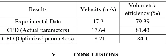
The results obtained from design of experiments and computational fluid dynamics are compared to experimental data. TABLE 1
Comparison of CFD and experimental data
Results Velocity (m/s) Volumetric
efficiency (%)
Experimental Data 17.2 79.39
CFD (Actual parameters) 17.64 81.43
CFD (Optimized parameters) 18.21 84.1
V. CONCLUSIONS
[image:4.612.167.440.455.547.2]Technology (IJRASET)
©IJRASET: All Rights are Reserved
1524
calculated data accuracy. Other considerable impact on precision of the numerical simulations has both grid coarseness and its structure, namely in areas of high pressure or velocity gradients. Choice of turbulence model is very important too. In this case, model RNG k-ξ performs relatively well, and the additional computational expense of more complex models was not justified.
Proper runner layout and diameter has to made, to achieve the best performance considering the vehicle layout.
REFERENCES
[1] Andrew McLandress, Roy Emerson, Philip McDowell, Christopher J. Rutland (1996) ‘Intake and In-Cylinder Flow Modeling characterization of Mixing and Comparison with Flow Bench Results’, SAE- 960635.
[2] Bohumil Mares and Pavel Baumruk (1997) ‘Intake and Exhaust Manifolds Simulation comparison with experiment ‘, International Journal of Heat Fluid Flow 31, 127-133.
[3] Chiavola O. (1999), ‘Multi dimensional CFD-transmission matrix modeling of I.C engine intake and exhaust system’, SAE transaction, 990355. FLUENT 5 User’s Guide, Fluent Inc., 1998.Fuchs T.R. and Rutland C.J. (2001),’Intake flow effects on combustion and emissions in a diesel engine’, Journal of heat transfer.
[4] Gosman D. (1999), ’State of the art of multi-dimensional modeling of engine reacting flows’, SAE transaction, 990157.