Technology (IJRASET)
CFD Investigation on Thermal Characteristics of
Air in a Square Duct using Perforated RIBS
Veeresh Chavan¹, Anandkumar S Malipatil²
¹˒²Department of PG Studies, Department of Thermal Power Engineering VTU ROKalaburagi-585105 India
Abstract - In the present work thermal characteristics of air in a square duct with perforated ribs having Aspect ratio (A.R) 2, 3 and 5 were investigated. Analysis is carried out by using a CFD tool. The flow and thermal characteristics of air in a square duct with different geometrical configurations of perforated ribs are studied. Primary objective is to analyze the effect of varied aspect ratios of the perforated ribs with varied pitch on the thermal characteristics and to estimate the pressure ratios in the square duct. This work is repeated for different configurations of perforated ribs and the results are reported for Aspect ratio (A.R) of 2,3,5 and pitch of 120mm, 180mm, 48mm and 72mm with holes of 3,4,8 in numbers each of 2mm diameter. From the present analysis it is observed that velocities are maximum in the domain for the aspect ratio of 2 due to obstruction in the channel. It is observed that for model with higher aspect ratio and longer pitch results in lower pressure drop and better heat transfer rate for the given inlet flow conditions.
Key words - Aspect ratio, Perforated ribs, Pitch, Square duct, Thermal characteristics.
I. INTRODUCTION
There are many uses in engineering industry that require addition or removal of heat and there are different type of heat exchanger devices that are utilized to carry out these applications. Heat exchanger techniques are widely used in process industries, refrigerators, car radiators, air conditioning equipments, thermal power house etc. The basic principle of heat exchanger is to accomplish flow of heat from hot fluid to cold fluid which is done according to Newton’s Law of Cooling. Perforated ribs arrays inside internal channels are regularly utilized as a part of heat exchanger systems to increase the heat transfer in turbine blade cooling channels. The impact of perforated ribs from the channel bottom on the heat transfer are analyzed. In this particular study we are utilizing perforated ribs to control the flow field and they can give a beneficial impact on the thermal performance.
Many analysts widely considered and conducted various experiments inner flow of air in various test sections like circular, non circular channels triangular, rectangular, polygonal, square, trapezoidal etc. Square channels are considered keeping in order to get effective freezing of turbine blades and vanes. In order to help heat transfer between energy shipping liquid and its surface perforated ribs are used. Vortex generator is used to upgrade heat exchange by making longitudinal vortices and these is made by putting obstacles in the stream course and henceforth these obstacles are known as vortex generators. Here perforated ribs are used as vortex generator.
II. REVIEW
Abhishek.R.H and Anandkumar S Malipatil (2016) [1] they experimentally studied that friction factor ratio decreases with rise in Reynolds number in case of smooth channel but from the graphs it is seen that square duct having perforated ribs vortex generators the friction factor ratio increases as Reynolds number increases because in these ducts better mixing of air takes place and the vortex generator blocks large amount of air in ducts at higher Reynolds number.
Anandkumar S Malipatil and Shravankumar.T.Sagar (2016) [2] studied the effect of Pitch to height ratio(p/e) on friction factor ratio in rectangular duct with perforated ribs obtained. With different aspect ratios, different heights of the ribs and various pitch lengths can be done. And upon comparing all the results it is concluded that; friction factor ratio decreases upon increasing the Pitch to height ratio (p/e). Friction factor0ratio at p/e=4 is 86% and at p/e=16 is 51% hence it decreases around 34%.
Technology (IJRASET)
the flow and the impact is diminishment in the friction factor. The point of Inclination of perforation won't make any impressive impact on pressure drop. Both heat transfer and pressure drop over the channel can be enhanced by expanding perforation diameter in both solid and perforated ribs as the Reynolds number increases then the Friction factor decreases.
Yang and Hwang (2003) [5] showed the numerical expectation of turbulent fluid flow and heat transfer characteristics for rectangular duct with porous baffle. In this study the turbulent governing equation are solved by a control volume-based finite difference method with turbulent model associated with wall function to describe the turbulent structure. The numerical results demonstrate that the flow design around the porous- and solid -type were different due to various transport phenomena, and it is essentially impacts the local heat transfer distributions.
III. METHODOLOGY
A. CAD Models Of Square DUCT With Perforated RIBS
The models are designed by using the computer aided drawing software and are analyzed by using a commercial CFD tool. This models are prepared and disceretized using CFD-Grid generation tool.
TABLE I: SPECIFICATION OF SQUARE DUCT WITH PERFORATED RIBS
Length of square duct 530mm
Breadth of square duct 30mm
Height of square duct 30mm
Aspect ratio 2,3,5
Height of perforated ribs 15mm,10mm,6mm
Diameter of holes 2mm
[image:3.612.69.540.257.489.2]Temperature of base plate 353K
Fig 1: CAD MODEL of AR 2, Pitch 120mm, 8 holes 2 mm dia.
B. CFD procedure
Computational flow domain: The computational flow domain of square duct with perforated ribs is designed with the help of geometry factors and the flow takes place inside the square duct as an air domain.
[image:3.612.40.546.573.715.2]C. Mesh Generation
TABLE II: MESH DETAILS Of AR 2, PITCH 120mm, 8 HOLES 2mm dia.
Type Tetra-hedral mesh
No. of elements 19293
No. of Nodes 13976
Technology (IJRASET)
D. Boundary Conditions
[image:4.612.100.525.139.251.2]Boundary conditions are mentioned on computational domain of square duct with perforate ribs. It is seen from fig 3.14 that the pressure gradually decreases from inlet to outlet and base plate temperature is at 353K.
[image:4.612.67.540.148.515.2]Fig 3: Boundary conditions of square duct with perforates ribs
TABLE III
BOUNDARY CONDITIONS
Inlet Mass flow inlet at 0.875 kg/s
Upper plate 300K
Outlet Pressure outlet
Wall boundary conditions Base Plate at 353K
TABLE IV FLUID PROPERTIES
Working Fluid Air
Density 1.22 kg/m3
Viscosity 1.78e-5 kg/m-s
Thermal Conductivity 0.0242 w/m K
Specific Heat 1006j/kg K
IV. RESULTS AND DISCUSSION
[image:4.612.87.516.563.689.2]A. For AR 2 and Pitch 120mm. 1) Streamline
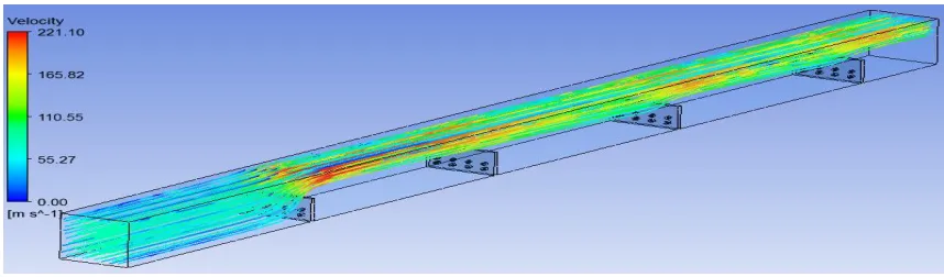
Fig 4: Streamlines coloured by Velocity, AR 2, Pitch 120mm
Technology (IJRASET)
and higher at outlet as it passes through the perforated ribs. The maximum velocity (221.10 m/s) is obtained at upper plate.
[image:5.612.73.531.108.244.2]2) Temperature
Fig 5: Temperature plots along Plane-1, AR 2, Pitch 120mm
Fig5. Shows that the temperature plots and it is seen that the temperature of 353K is maximum at the base plate and the temperature of 315K is achieved after passing through the perforated ribs.
[image:5.612.50.543.305.451.2]3) Pressure*
Fig 6: Pressure plots along Plane-1, AR 2, Pitch 120mm
Fig6. Shows that the pressure plots with AR 2 and it is observed that the pressure is gradually decreases from inlet to outlet, and after passing through the each perforated ribs it is observed that pressure is of about 0.10 bar.
[image:5.612.72.528.518.664.2]4) Velocity*
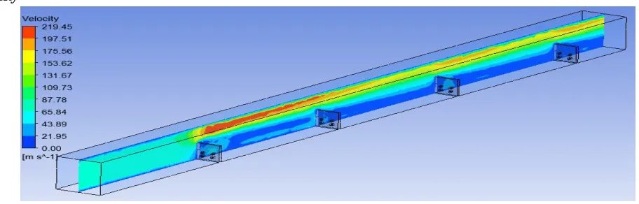
Fig 7: Velocity plots along Plane-1, AR 2, Pitch 120mm
Technology (IJRASET)
[image:6.612.66.536.89.209.2]5) Heat Flux
Fig 8: Heat flux plots along Plane-1, AR 2, Pitch 120mm
Fig8: Shows that heat flux plots with AR 2 and 120mm pitch. It is seen that the maximum heat flux in the domain found to be 33080 W/m² and heat flux distribution throughout the base plate is not uniform.
V. CONCLUSIONS
CFD analysis is carried out to understand the thermal characteristics of air in a square duct using perforated ribs with varied Aspect ratios of 2, 3 and 5 for varied pitch of 120mm,180mm,48mm and 72mm with holes of 3,4,8 in numbers each of 2mm diameter. Contours are plotted for Temperature, Pressure and Domain velocity at various planes and following conclusions were drawn.
A. It is observed that velocities are maximum in the domain for the aspect ratio of 2 due to obstruction in the channel.
B. From pressure contours it is observed that higher the aspect ratio lower the pressure drop in the channel.
C. Pressure drop in the domain for the Aspect ratio of 5 found to be very minimal and the air flow distribution found to be throughout the channel resulting better heat transfer rate.
D. From the above observations it could be concluded that higher the Aspect ratio and larger the pitch lower the pressure drop and higher rate of heat transfer in the domain.
VI. ACKNOWLEDGEMENT
I wish to express my special gratitude to my guide Prof. Anandkumar.S.Malipatil, Department of Thermal Power Engineering, Dept., of PG Studies, VTU regional office, Kalaburagi for his inspiration constant supervision, direction and discussions in successful completion of this project.
REFERENCES
[1] Anandkumar S Malipatil, Shravankumar.T.Sagar, “Flow Analysis of Air in a Rectangular Channel Using Perforated Rectangular Rib”, International Journal for Research in Applied Science & Engineering, Volume 4 Issue I, January 2016.
[2] Abhishek.R.H, Anandkumar S Malipatil, “Flow Characteristics of Air in Square Channel Using Perforated Ribs” IOSR Journal of Mechanical and Civil Engineering (IOSR-JMCE) Volume 13, Issue 1 Ver. II (Jan. - Feb. 2016), (PP 106-112).
[3] MaziyarJalaal, Ahmad Khoshnevis, FaramarzTalati, EsmaeilEsmaeilzadeh “Analysis of Heat-Transfer Enhancement and Design Parameters of Heat-Sink with Perforated Rectangular Ribs”, 12th Fluid Dynamics Conference, Babol Noshirvani University Of Technology, 28-30 April 2009.
[4] Ahmad Khoshnevis, FaramarzTalati, MaziyarJalaal, EsmaeilEsmaeilzadeh “Heat Transfer Enhancement of Slot and Hole Shape Perforations In Rectangular Ribs of a 3-D Channel”,17th. Annual (International) Conference on Mechanical Engineering-ISME2009 May, 2009, University of Tehran, Iran
[5] Y. T. Yang and C. Z. Hwang, “Calculation of turbulent flow and heat transfer in a porous-baffled channel”, Int. J. Heat Mass Transfer, 2003, Vol. 46, pp. 771-780.
[6] Han, J.C., Park, J.S. and Lei, C.K. (1985). Heat Transfer Enhancement in Channels With Turbulence Promoters, ASME Journal of Eng. for Gas Turbines and Power, vol.107, (pp.628-635).
[7] Çalışkan, S. (2013). Flow and heat transfer characteristics of transverse perforated ribs under impingement jets, International Journal of Heat and Mass Transfer 66 (pp.244-260).
[8] Karwa, R., Maheshwari, B.K., Karwa, N. (2005). Experimental study of heat transfer enhancement in an asymmetrically heated rectangular duct with perforated baffles, International Communications in Heat and Mass Transfer 32 (pp.275–284).
[9] Abdullah H. AlEssa and Mohammed Q. Al-Odat “Enhancement of Natural Convection Heat Transfer From a Fin by Triangular Perforations of Bases Parallel And Toward Its Base”, The Arabian Journal for Science and Engineering, Volume 34.
[10] Liang-Bi Wang, Wen Qaun Tao, Qiu- Wang Wang, Tsun Tat Wang “experimental study of developing turbulent flow and heat transfer in ribbed convergent divergent square duct” International Journal of Heat and fluid flow 22(2001)603-613.