Simulative Study and Investigation of Cavity
Formation and Its Effect on the Performance of
Water Jet Pump
Rajesh Ranjan1, Vardan Singh Nayak2
1
M.Tech Scholar Mechanical Engg. Dept. VIST BHOPAL 2
Asst. ProfessorMechanical Engg. Dept. VIST BHOPAL
Abstract: For water jet systems operating in any type of machines cavitations are the phenomenon that often occurs. The presence of vapour in the flow affects the performance of the water jet system and as the cavity grows the system efficiency drastically reduces to a level where the system cannot operate normally. Liquid handling capacity of the processing plant has become crucial with increasing field water cut and more jet pump installations. Jet pump performance optimization for maximum efficiency has now started to play an important role in not only reducing the burden of the processing facility but also in improving the production profile of the wells. This study will discuss the use of a methodology based on an in-house developed algorithm for monitoring the efficiency of the pumps, with supporting field examples. This paper will also make an attempt to analyze the effect of different operating conditions on the pump performance curves published in the literature.In analyzing the performance of pump systems, the presence of cavitation can have a significant impact on the perfor mance of the pump. Cavitation bubblesemerge when the local static pressure of the working fluid (a liquid) falls below the vapor pressure. Vi-gorous cavitation can lead to loss of head rise and, in many cases, structural structural damage due to erosion from collapsing vapor bubbles striking the pump body. When we change the inlet pressure the pressure drop is decreased and cavity is reduced or vapor pressure is reduced in efficient manner. Again when we simulate the problem by increasing both inlet and outlet pressure same phenomenon we found. Beyond the inlet pressure (6.49e5 Pascal) no change will appear and in whole simulation system is stable in nature so fluid flow system is stable in nature which shows good results and excellent accuracy that maintain.
Key words: Jet pump, Cavity, Numerical Simulation, CFD, Ansys, Bubble Cavity, developed cavity etc.
I. INTRODUCTION
For water jet systems operating in any type of machines cavitations are the phenomenon that often occurs. The presence of vapour in the flow affects the performance of the water jet system and as the cavity grows the system efficiency drastically reduces to a level where the system cannot operate normally. Liquid handling capacity of the processing plant has become crucial with increasing field water cut and more jet pump installations. Jet pump performance optimization for maximum efficiency has now started to play an important role in not only reducing the burden of the processing facility but also in improving the production profile of the wells. This study will discuss the use of a methodology based on an in-house developed algorithm for monitoring the efficiency of the pumps, with supporting field examples. This paper will also make an attempt to analyze the effect of different operating conditions on the pump performance curves published in the literature.
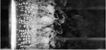
A. Bubble Cavitation
Individual bubbles are travelling with the convecting flow as they expand and collapse. This phenomenon occurs for low pressure gradient flows, corresponding o a flow around a hydrofoil at a low incidence angle (Figure 1.1).
[image:2.612.215.396.637.723.2]II. LITERATURE
1.Hou-lin LIU*, Dong-xi LIU, Yong WANG, Xian-fang WU, Jian WANG. Considering the compressibility of the cavity in the cavitating flow, this paper presents a modified k-Ȧ model for predicting the cavitating flow in a centrifugal pump, in which the
modified k-Ȧ model and Schnerr-Sauer cavitation model were combined with ANSYS CFX. To evaluate the modified and standard k-Ȧ models, numerical simulations were performed with these two models, respectively, and the calculation results were compared
with the experimental data. Numerical simulations were executed with three different values of the flow coefficient, and the simulation results of the modified k-Ȧ model showed agreement with most of the experimental data. The activating flow in the centrifugal pump obtained by the modified k-Ȧ model at the design flow coefficient of 0.102, was analyzed. When the cavitation
number decreases, the cavity initially generates on the suction side of the blade near the leading edge and then expands to the outlet of the impeller, and the decrease of the total pressure coefficient mainly occurs upstream of the impeller passage, while the downstream remains almost unaffected by the development of cavitation. 2.Frederick STERN, Zhaoyuan WANG, Jianming YANG-An overview is provided of CFDShip-Iowa modelling, numerical methods and high performance computing (HPC), including both current V4.5 and V5.5 and next generation V6. Examples for naval architecture highlight capability and needs. High fidelity V6 simulations for ocean engineering and fundamental physics describe increased resolution for analysis of physics of fluids. Uncertainty quantification research is overviewed as the first step towards development stochastic optimization. 3.H. Nouraei, K. Kowsari, B. Samareh, J.K. Spelt, M. Papini-Abrasive slurry jet micro-machining (ASJM) uses a relatively high-speed jet of fine abrasive slurry to precisely machine controlled-depth micro-features such as channels. Existing surface evolution models, developed for air-driven erosion processes, cannot account for the effect of slurry flow on the channel sidewall erosion that leads to the progressive channel widening observed in the ASJM of ductile materials. This paper presents a novel numerical–empirical model to predict the profiles of micro-channels in ductile materials (i.e. poly methyl methacrylate (PMMA), 6061-T6 aluminum alloy, 316L stainless steel and Ti–6Al–4V titanium alloy) using ASJM. The specific erosion rates of these materials were measured as a function of jet angle using a 10 μm nominal diameter aluminum oxide slurry. The erosion rate-impact angle relations were corrected using computational fluid dynamic (CFD) models to account for the local impact angles and velocities of the particles. The erosion rate-impact angle relations were then used in three-dimensional CFD models to obtain the particle trajectories, rate-impact angles, and velocities on a shallow eroded profile, and thus predict the erosion for deeper profiles. The model was verified by comparison with experiments which showed the previously-observed widening of the machined channels as the depth increased due to secondary erosion by particles impacting the channel sidewalls. The widening effect was found to be substantial in the PMMA but less important in Ti–6Al–4V titanium alloy due to its greater erosion resistance. The numerical–empirical approach could accurately estimate the widening and predicted the channel cross-sections up to an aspect ratio of approximately 1 with a maximum error of less than 5%. 4.Jinya Zhang, Cong Xu, Yongxue Zhang, Xin Zhou-Liquefied natural gas (LNG) cryogenic submerged pumps are important transmission devices in LNG terminals and filling stations. In this study, the impeller of a two-stage LNG submerged pump was designed by the quasi-3D hydraulic design method based on the S1 and S2 relative stream surfaces theory. In the design procedure, the finite element method (FEM) with a quadrilateral nine-node element was adopted for the S1 stream surfaces calculation, and the quasi-orthogonal method was used for the average S2 stream surface calculation. The flow field was obtained by the iterative computations of S1 and S2 stream surfaces. Given a reasonable velocity moment distribution along streamlines considered cavitation, the blade drawing was realized by iterating the camber lines and circulation equations on an average S2 stream surface. Moreover, a steady numerical simulation of the designed pump was conducted. The simulation result showed that the head of the designed pump was 260.15 m and the efficiency was 62.82% at the designed flow rate condition. The net positive suction head required (NPSHr) at the conditions with 0.9 Q0, 1.0 Q0 and 1.1 Q0 were, respectively, 1.69 m, 2.54 m and 3.12 m, which met the industrial needs. Furthermore, both the cavitation and hydraulic performance of an impeller designed by the method presented in this study were better than those of an impeller which was designed by the two-dimensional method.
III. OBJECTIVE OF THE STUDY
A. Set boundary conditions for internal flow. B. Use the mixture model with cavitations effects.
C. Calculate a solution using the pressure-based coupled solver.
A numerical investigation of Cavitating flows using the mixture model has to be implemented in the FLUENT commercial code. The inter-phase mass flow rate has to be modelled with a simplified Rayleigh equation applied to bubbles uniformly distributed in computing cells. The cavitation model has to be validated for the flow around a blunt fore-body cavitator.
D. Problem Formulation
To simulate Cavitating flows, the two phases, liquid and vapour, need to be represented in the problem, as well as the phase transition mechanism between the two. Here, we consider at one fluid, single-fluid (mixture), introduced through the local vapour volume fraction and having the spatial and temporal variation of the vapour fraction described by a transport equation including source terms for the mass transfer rate between the phases. The numerical model solves the Reynolds averaged Navier-Stockes equations, coupled with a localized vapour transport model for predicting cavitation.
IV. METHODOLOGY
Basic Steps to perform CFD Analysis
A. Preprocessing
1) CAD Modeling: Creation of CAD Model by using CAD modeling tools for creating the geometry of the part/assembly of which we want to perform FEA. CAD model may be 2D or 3d.
2) Meshing: Meshing is a critical operation in CFD. In this operation, the CAD geometry is discretized into large numbers of small Element and nodes. The arrangement of nodes and element in space in a proper manner is called mesh. The analysis accuracy and duration depends on the mesh size and orientations. With the increase in mesh size (increasing no. of element), the CFD analysis speed decrease but the accuracy increase.
3) Type of Solver: Choose the solver for the problem from Pressure Based and density based solver. Physical model: Choose the required physical model for the problem i.e. laminar, turbulent, energy, multiphase, etc.
4) Material Property: Choose the Material property of flowing fluid
5) Boundary Condition: Define the desired boundary condition for the problem i.e. velocity, mass flow rate, temperature, heat flux etc.
B. Solution
1) Solution Method : Choose the Solution method to solve the problem i.e. First order, second order 2) Solution Initialization: Initialized the solution to get the initial solution for the problem.
C. Post processing.
Post Processing: For viewing and interpretation of Result. The result can be viewed in various formats: graph, value, animation etc. CFD Analysis of Water jet pump model using Ansys Fluent 14.5
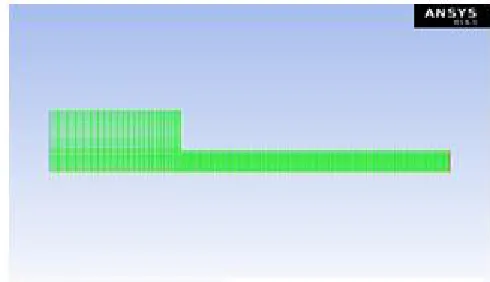
[image:4.612.181.426.580.721.2]1) Pre-processing: Mesh:Generate the mesh in the Ansys Mesh software .
Element Edge Length =3.15e-003 m No. of Nodes = 14058
No. of Element = 8047
Fluent setup: After mesh generation define the following setup in the Ansys fluent. 2) Problem Type : 2D axisymmetric
3) Type of Solver: Pressure-based solver.
4) Physical model: Viscous: K-epsilon two equation turbulence model. 5) Material Property: Flowing fluid is water
6) Density of water = 1000 kg/m3
7) Viscosity = 0.001kg/m-sSecond fluid is water (vapour) 8) Viscosity = 1.26e-6 kg/m-s
Phases- Water is select for primary phase Water vapour is secondary phase
Cavitation model is enabled –No. of mass transfer mechanism is 1 and ensure that mass transfer is occurred from liquid phase to water vapour. In cavitation model- Bubble density is 1e13kg/m3 and vaporization pressure is 3250 pa. For the multiphase mixture model, we will specify conditions for the mixture (i.e., conditions that apply to all phases) and the conditions that are specific to the primary and secondary phases. In this tutorial, boundary conditions are required only for the mixture and secondary phase of two boundaries: the pressure inlet (consisting of two boundary zones) and the pressure outlet. The pressure outlet is the downstream boundary, opposite the pressure inlets.
D. Boundary Condition:
1) Pressure inlet for the mixture-Gauge Total Pressure-4.49E+05 to 6.49E+05 Pascal as case 1
2) Temperature inlet – 290k, 295 k and 300 kas Case 2Supersonic/Initial Gauge Pressure (Standard operating pressure)-449000 Pascal
3) Pressure inlet for the phase that is vapour –volume fraction is zero. 4) Pressure outlet for the mixture- Gauge Total Pressure-95000 Pascal 5) Pressure outlet for the vapour-Backflow vapour fraction is set to zero
E. Solution
1) Solution Method
Pressure- velocity coupling – Scheme -SIMPLE Pressure – Standard
Momentum – Second order
Turbulent Kinetic Energy (k) Second order Turbulent Dissipation Rate (e) Second order
Solution Initialization: Initialized the solution to get the initial solution for the problem. 2) Run Solution: Run the solution by giving 2000 no of iteration for solution to converge.
3) Post-Processing: For viewing and interpretation of Result. The result can be viewed in various formats: graph, value, animation etc.
[image:5.612.202.414.584.715.2]V. RESULTS AND DISCUSSION
It is noticed that dramatic pressure drop at the flow restriction in Figure 1: Contours of Total Pressure. Low static pressure is the major factor causing cavitations. In Contours image we see that as the pressure is increased cavity will be decreased continuously.
[image:6.612.121.499.315.488.2]Figure 2: Contours of Turbulent Kinetic Energy
Figure 3: Contours of Velocity stream
[image:6.612.118.497.525.710.2]Figure 5: Contours of Vapour volume fraction at inlet pressure is 4.49e5 Pascal
Figure 6: Contours of Vapour volume fraction at inlet pressure is 5.49e5 Pascal
[image:7.612.126.490.561.712.2]Figure 8: Contours of Vapour volume fraction at Operating Temperature 300 k
Figure 9: Contours of Vapour volume fraction at Operating Temperature 295 k
[image:8.612.100.517.517.712.2]Results table no. 1
OPERATING TEMPERATURE
PRESSURE INLET
VAPOUR VOLUME FRACTION
(CAVITY)
300˚ K 4.49E5 Pascal 1.00e+00
300˚ K 5.49E5 Pascal 9.82e-01
300˚ K 6.49E5 Pascal 8.52e-01
Results table no. 2 OPERATING
TEMPERATURE
PRESSURE INLET
VAPOUR VOLUME FRACTION
(CAVITY)
300˚ K 6.49e5 Pascal 7.52e-01
295˚ K 6.49e5 Pascal 7.12e-01
290˚ K 6.49e5 Pascal 6.34e-01
Graph no.1 Temperature Inlet VsVapour Volume Fraction (Cavity)
Graph no.2 Pressure InletVsVapour Volume Fraction (Cavity)
VI. CONCLUSION
REFERENCES
[1] Hou-lin LIU*, Dong-xi LIU, Yong WANG, Xian-fang WU, Jian Application of modified k-Ȧ model to predicting cavitating flow in centrifugal pump
Research Center of Fluid Machinery Engineering and Technology, Jiangsu University, Zhenjiang 212013, P. R. China
[2] FREDERICK stern, zhaoyuanwang, jianming yang Computational ship hydrodynamics: nowadays and way forward frederick stern, journal of fluids and structures volume 32, pages 1-158 (july 2012)
[3] H. nouraei, k. kowsari, b. samareh, j.k. spelt, m. papinicalibrated cfd erosion modeling of abrasive slurry jet micro-machining of channels in ductile materials journal of manufacturing processes volume 23, pages 1-328 (august 2016)
[4] Jinyazhang, congxu, yongxuezhang, xinzhouquasi-3D Hydraulic design in the application of an lng cryogenic submerged pumpjournal of natural gas science and engineering volume 29, pages a1-a6, 1-582 (february 2016)
[5] Deshengzhang, weidongshi, b.p.m. (bart) van esch, lei shi, micheldubuisson, Numerical and experimental investigation of tip leakage vortex trajectory and dynamics in an axial flow pump journal of compute fluid dynamics volume 112, 2007
[6] Hou-linliu, dong-xi liu, yongwang, xian-fang wu, jianwangApplication of modified κ-ω model to predicting cavitating flow in centrifugal pumpwater science and engineering volume 6, issue 3, pages 241-363 (july 2013)
[7] Manjit k. singh, dhruvaprasad, aditya k. singh, mihirjha, and rohittandon Large Scale Jet Pump Performance Optimization in a Viscous Oil Field IJARIIT, OCTOBER 2016
[8] Pooriaakbarzadeh, ebrahimakbarzadehHydrodynamic characteristics of blowing and suction on sheet-cavitating flows around hydrofoils ocean engineering volume 114, pages 1-302 (1 march 2016
[9] M. sedlar, b. ji, t. kratky, t. rebok, r. HuzlikNumerical and experimental investigation of three-dimensional cavitating flow around the straight naca2412 hydrofoil ocean engineering volume 123, pages 1-458 (1 september 201
[10] Zhiyingwang, biaohuang, guoyuwang, mindizhang, fufengwangExperimental and numerical investigation of ventilated cavitating flow with special emphasis on gas leakage behavior and re-entrant jet dynamics ocean engineering volume 108, pages 1-832 (1 november 2015
[11] Qin wu, biaohuang, guoyuwang, yuangaoExperimental and numerical investigation of hydroelastic response of a flexible hydrofoil in cavitating flow international journal of multiphase flow volume 74, pages 1-194 (september 2015
[12] Z xiao, x p long1, q lyu and m s xules investigation on cavity shedding of a clark-y hydrofoil under different attack angle with an integration method earth and
environmental science, volume 22, erosion and cavitating flows
[13] Cong-tu ha, warn-gyu park, chul-min jung Numerical simulations of compressible flows using multi-fluid models international journal of multiphase flow volume 74, pages 1-194 (september 2015
[14] Md. mashudkarim, mohammadshakilahmmed Numerical study of periodic cavitating flow around naca0012 hydrofoil ocean engineering volume 55, pages 1-240 (1 december 2012)
[15] Qinhui Wang, ZhongyangLuo, Mengxiang Fang, Mingjiang Ni, Kefa Cen Development of a new external heat exchanger for a circulating fluidized bed boiler. Chemical Engineering and Processing: Process IntensificationVolume 42, Issue 4, Pages 249-335 (April 2003)
[16] Jonghyunkim, joon sang Numerical study of cloud cavitation effects on hydrophobic hydrofoils leeInternational journal of heat and mass transfer volume 83, pages 1-850 (april 2015
[17] Giangcheng, min xua, zhendongzhang, nailiuxiemulti-Physical fields coupling simulation and performances analysis of a novel heated-tip injectorjournal of thermophysics and heat transfer, july, vol. 30, no. 3 : PP. 587-598
[18] Marina olsson Numerical investigation on the cavitating flow in a waterjet pump master’s thesis 2008:44 issn 1652-8557
[19] Guang pan and linlu Numerical investigation of a pump jet propulsor based on cfd international journal of control and automation vol.8, no.11 (2015)
[20] Eshant s. rami1 pathan2 a.m., Numerical investigation of cavitation of centrifugal pump international journal of advance engineering and research development volume 1, issue 12, december -2014.
[21] Liu, H. L., Wang, Y., Yuan, S. Q., Tan, M. G., and Wang, K. 2010. Effects of blade number on characteristics of centrifugal pumps. Chinese Journal of Mechanical Engineering, 23(6), 742-747. [doi:10.3901/CJME. 2010.06.742]
[22] Liu, L. J., Li, J., and Feng, Z. P. 2006. A numerical method for simulation of attached cavitation flows. International Journal for Numerical Methods in Fluids, 52(6), 639-658. [doi:10.1002/fld.1192] Olsson, M. 2008.
[23] Pierrat, D., Gros, L., Couzinet, A., Pintrand, G., Le Fur, B., and Gyomlai, Ph. 2008 Numerical Investigation on the Cavitating Flow in a Waterjet Pump. Ph. D. Dissertation. Sweden: Chalmers University of Technology..
[24] . Sato, T., Nagahara, T., and Suzuki, S. 2009 Experiment and numerical investigations of leading edge cavitation in a helico-centrifugal pump. The 12th International Symposium on Transport Phenomena and Dynamics of Rotating Machinery..
[25] IAHR. Schnerr, G. H., and Sauer, J. 2001.Cavitation analysis on double-suction volute pump. Third International Association for the History of Religions (IAHR) International Meeting of Workshop on Cavitation and Dynamic Problems in Hydraulic Machinery and System.Brno:
[26] Sezal, I. H., Schmidt, S. J., Schnerr, G. H., Thalhamer, M., and Förster, M. 2006. Physical and numerical modeling of unsteady cavitation dynamics. Fourth International Conference on Multiphase Flow. New Orleans: ICMF
[27] Singhal, A. K., Athavale, M. M., Li, H. Y., and Jiang, Y. 2002. Shock and wave dynamics of compressible liquid flows with special emphasis on unsteady load on hydrofoils and on cavitation in injection nozzles. Sixth International Symposium on Cavitation. Wageningen: Maritime Research Institute Netherlands. [28] Wang, Y., Liu, H. L., Yuan, S. Q., Tan, M. G., and Wang, K. 2011. Mathematical basis and validation of the full cavitation model. Journal of Fluids
Engineering, 124(3), 617-624. [doi:10.1115/1.1486223] .
[29] Wu, J. Y., Wang, G. Y., and Shyy, W Impact of turbulence and compressibility modeling on three-dimensional cavitating flow computations. 33rd AIAA Fluid Dynamics Conference and Exhibit. Orlando: American Institute of Aeronautics and Astronautics.