www. ijraset.com Volume 2 Issue X, October 2014
ISSN: 2321-9653
International Journal for Research in Applied Science & Engineering
Technology(IJRASET)
Automatic Railway Bridge for Disabled Persons
C.M.Arun Kumar
Department of Electronics and Communication Engineering, University College Of Engineering,Pattukkotai, India.
Abstract: The Primary objective of Automatic Railway Bridge System is to help the physically Challenged Passenger to move from one Platform to another. Crossing the railway track inside the railway station is very difficult. But it is quite difficult to the handicapped and aged persons to cross the railway track without the help of others. In this paper the agents make use of a set of resources - train characteristics, driving rules and information about other trains - to generate their action policy. The proposed system uses the train time for opening and closing of bridges. It also confirms the presence of the train using a sensor which is placed at a certain distance away from the platform. The RUNE technical solution is based on GNSS receivers: navigation data will come from GPS with differential EGNOS corrections (European Geostationary Navigation Overlay Service) to enable autonomous and reliable determination of train position, velocity under practically all environmental conditions. While persons try to cross platform by avoiding the over bridge there is chance for the accidents. This can be avoided by using this technique and very helpful for disabled person.
Keywords and phrases: Global Navigation Satellite System (GNSS); Multi-Aspect Signaling Systems (MASS); Operational Control Center (OCC); Railway User Navigation Equipment (RUNE).
I. INTRODUCTION
Indian railway network is the one of the biggest rail network in the Asia.Railways are recognized as a one of the safest mode of mass transportation and Safety has been recognized as the key issue for the railways networks.To make it a safe and reliable system is an enormous challenge. Unmanageable platform crossings are one of the problem areas for the Indian Railways, and one of the major issues of death. In spite of various measures taken by the Indian Railways, platform crossing deaths have continued to occur, that too frequently.
Crossing the railway track inside the railway station is very tedious especially for handicapped and disabled person. They find it quite difficult to walk over the over bridge for crossing the platform. To solve this problem we use a new approach called Automatic Railway Bridge System. This can be installed in major subway stations and stations where the distance between the station platforms is increased due to curve.
Recently, advancements in information technology have enabled applying sensors to railway environments such as PIR sensors. Also technology for wireless data transfer has also been developed which helps in updating the train timing. The objective of PIR sensor in railway station is to sense passenger’s movements on the bridge before it opens. Therefore when emergency situation arises, immediate recognition and response to the situation is possible.
In this paper, we not only ensure an easy method for track crossing but also platform safety. It shows train signal (red or green) and if necessary we can use audio telling the arrival of train before stepping over the bridge. If necessary, for safety opening and closing of bridge we can use train navigation system, RUNE system. The RUNE project (Railway User Navigation Equipment) is aimed at demonstrating the use of GNSS Integrity and Safety of Life service characteristics for defining a satellite-based system to perform train location for safe railway applications. The primary objective is to demonstrate the improvement of the train self capability in determining its own position and velocity which will help in stopping the train if necessary. This paper introduces overall system overview, configuration and detection process of the system.
II. PROPOSED ALGORITHM
The main modules in this project are PIR sensor, IR sensors, drivers and relays, microcontroller unit, LCD display and bridge operation motors. The IR sensors are connected at the track to identify the arrival of train. The PIR sensor is connected at the two ends of the bridge to identify whether anybody on the bridge. The system consists of data acquisition unit, processing unit and information multicasting unit.
Figure 1: Railway Track Figure 2: Alert Signals
A. Stop:
This requires a passenger to stop and wait until next instruction proceeds. This also indicates a danger sign. This signal is provided 10min before the arrival of train.
B. Caution:
This signal alerts persons not to enter the bridge or who were on the bridge have to leave as soon as possible. It also indicates the next symbol is a sign for train arrival. This signal is given 15min before train arrival.
C. Attention:
This shows that the train is ready to move and the bridge is about to close. It also alerts the passengers to get into the train.
D. Proceed:
It indicates the bridge is now closed and the people who are waiting to cross the track can use the bridge.
III. DETECTION PROCESS
The detection process is divided mainly into two steps i.e. train detection and object/human detection. The train detection determines the train state to prevent a train from being mistaken.
A. Train detection:
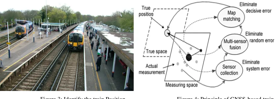
[image:3.612.32.479.530.690.2]Train can be detected by collecting information from the station PC. Also it can be detected by using an IR sensor placed along the track. Currently, freight trains travelling on a railway line obey various safety standards. On the other hand, railways, like other modes, have to cope with a number of new challenges and are under economic pressure to improve and optimize significantly their operations in terms of track occupancy, safety, productivity and customer satisfaction. As we have mentioned already RUNE mechanism we can implement it in maintaining safety of train positioning and detecting it.
Figure 3: Identify the train Position. Figure 4: Principle of GNSS-based train integrated positioning
www. ijraset.com
Volume 2 Issue X, October 2014
ISSN: 2321-9653
International Journal for Research in Applied Science & Engineering
Technology(IJRASET)
additional, accurate information, and add significant strength to the overall system. The railways have a consolidated experience using other means of navigation, which may not be ideal, but are well known and familiar to the operators. RUNE system is based on the principle of GNSS (Global Navigation Satellite System) receivers. The primary objective of the integration of GNSS in the train equipment is to demonstrate the improvement of the train self capability in determining its own position and velocity, which helps for calculating the speed of the train. The Demonstrator Navigation Sensors are in charge to provide additional navigation information to the evaluation system in order to integrate the Train speed and distance provided by the on board ATC (Automatic Train Control). The Subset is constituted by:
GNSS Receiver: used for Train position and Speed determination. The receiver will make use of GPS and EGNOS signals. Inertial Navigation System: in case of unavailability of GNSS signals it helps in computation of the Train Position and Speed. Doppler radar: In charge to provide to RES the Train Speed. Data provided by the Doppler radar will be not fused with the data provided by other sensors but only recorded and used for off line-verification and evaluation purpose. Advantages of satellite-based systems over traditional systems of navigation and positioning in the railway environment are mainly attributable to having the required information in real-time. This makes it possible to manage traffic better and helps in reducing infrastructure and maintenance cost. Another method of train detection can be done using Towards an Optimal Driving Trains in Single Line Using Crossing Loops. Nowadays, the need for information systems and coordination between them is fundamental in all areas. In this paper we propose to use these methods for rail transport. It checks the maximum number of trains allowed in the stretch based on the size of the trains and the crossing loop and grants or denies trains permission to enter certain stretches of the track. When one train travels along the track in a positive direction and the other trains travel along the same stretch in a negative direction. The aim of the study is to coordinate trains so that when they meet a crossing loop they can cross without colliding and/or halting. For further safety, we can calculate the speed of the train using following equation
The Equation is used to calculate the ideal speed for Train a so that Train a and Train b arrive at their positions of safety at the same time
V= (Ssec + Lt + SSP b –SSP a-b)/tt *3.6
Where S sec is the safety distance between the locomotive of Train A and the last wagon of Train b (in meters) calculated using the equation:
S sec = halt Dist O + halt Dist O x sec Level O,Lt is the length of Train b (in meters);
Further safety can be ensured by using the standards used in Brazil which is an old system based on Block Sections (BSs). A BS is a stretch of track of fixed or variable length that only one train can enter at a time. In this system, when a train enters a BS, the section is closed to any other train. Hence, a BS is only made available again once the train using it has left. However, with the greater demand for track use, passive permissions allowing more than one train to enter a particular BS were introduced. Such permissions are not safe, as with the increasing number and speed of trains the BS send to become smaller. For greater safety, trains travelling in the same direction must keep a B S free between them, thus reducing the capacity of the line. This type of traffic was given the name Multi-Aspect Signaling Systems (MASS).
[image:4.612.189.440.608.709.2]In this system lights with standard colors (red, yellow and green) tell the driver of the train whether he can or cannot enter a BS: a green light means that the train can enter the next BS; a yellow one indicates that the driver must enter more slowly as a cautionary measure; and a red light means that the driver must halt the train as there is another train on the other side of the light and therefore a very high risk of a collision from behind.
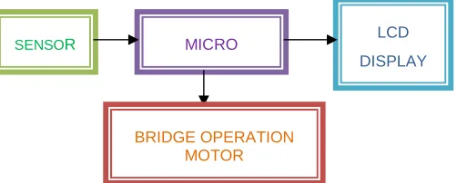
Figure 5: Block diagram for Platform Bridge MICRO
SENSOR LCD
DISPLAY
Other signaling systems have been used, particularly in urban rail transport systems, where a high level of safety is required. These methods were improved with new technologies such as global positioning by satellite and wireless communication. One of these technologies is known as Communication Based Train Control (CBTC) and uses systems such as Global Positioning by Satellite (CPS) and Global Navigation Satellite Systems (CNSS).
Operational Control Center (OCC) checks the position of other trains travelling on the same section in the opposite direction. The OCC only authorizes a stationary train to move or not after these checks have been made. These safety checks are currently carried out by the OCC with the systems referred to above but are unable to avoid the need for trains to halt.
In the event of any unforeseen incident before it reaches the position of safety, the agent involved recalculates the new arrival time and hence a new mean journey speed. However, if the new time calculated results in some rule or speed limit on the stretch being broken, the agent reports that it is unable to complete the journey in this time and passes the change in time and speed to another agent on the stretch so that the later can calculate the new estimated arrival time at the position of safety.
Trains travelling in the same direction are also subject to a safety rule that takes into account the emergency halt distance. Calculations involving this distance are always based on the trains weight and current speed. Hence, a train that has another train in front of it travelling in the same direction is subject to this additional distance limitation.
Another approach for safety is an algorithm based on an energy efficient control strategy that allows train control and driving modes to be determined and so improve the spacing between trains. Trains travelling in the same direction are also subject to a safety rule that takes into account the emergency halt distance. Calculations involving this distance are always based on the trains weight and current speed. Hence, a train that has another train in front of it travelling in the same direction is subject to this additional distance limitation.
In addition to enhancing safety, as its name implies, the safety distance also helps to increase the capacity of the line, as two trains travelling close together in the same direction can be considered as only one train, a principle that has been defended by many experts in an attempt to increase the capacity of railway lines. The safety rule for trains travelling in the same direction is not only the responsibility of the DA driving the train at the rear.
B. Human detection:
For safety purpose, the presence of human on the bridge is necessary. For that purpose a PIR sensor is placed along the bridge. When a human is detected along the bridge an alarm will be produced to alert the security personnel before opening the bridge. The detection results of dangerous factor in platform monitoring area mainly classified such a situations like a fallen object in the area. To determine object the proposed system considers only movements in monitoring area in OFF state. Moreover, it detects object coming from outside of dangerous area by using backtracking method which tracks movements in previous frames
IV. CONCLUSION
The aim of this paper was to develop a system that could help the disabled person to cross the railway platform in far easy manner. The main contributions this study has made were the establishment of driving rules to allow trains to travel economically while giving priority to safety; the inclusion of additional trains travelling in the same direction at a safe distance apart. This method helps in reducing the time and area requirement. Further in future we can make the bridge as a rotating one for the effortless crossing of railway track for disabled persons. Later in future a new recognition method using stereo vision which calculates automatically volume of objects in bridge can be used. Moreover, we consider other dangerous factors, such as safety accidents as fall between a platform and a train, getting stuck between the bridges etc .Moreover; we are considering an effective information transmission system for the controller.
REFERENCES
[1] I.Yoda,k.Sakaue.’’Ubiquitous Stereo Vision For Controlling Safety on Platform Railroad Station,’’IEEJ Tr.on Electronics,Information and Sysyems
Vol.124, No.3, pp.805-811,2004.
[2] The RUNE project: Navigation Performance of GNSS Based Railway User Navigation Equipment, NAVITEC 2004
[3] N.Paragios and V.Ramesh. “An MEF-based approach for real-time Subway monitoring.” In IEEE Conference on Computer Vision and Pattern Recognition, 2001
[4] Polivka A, Filip A .Satellite-based positioning for CBTC. In: Proceedings of 2nd international conference on Reliability, safety and diagnostics of transport structures and means, Pardubice, 2005
[5] Xu T, Tang T, Gao C, et al. Dependability analysis of the data communication system in train control system. Sci China Ser E-Tech Sci, 2009,52(9): 2605–2618
[6] Fan L J. Application of ERTMS/ETCS in train control system. ChinRail Sci, 2003, 24(3): 98–103
[7] Saab S. A map matching approach for train positioning part II: application and experimentation. IEEE T Veh Technol, 2000,49(2):476–484
www. ijraset.com
Volume 2 Issue X, October 2014
ISSN: 2321-9653
International Journal for Research in Applied Science & Engineering
Technology(IJRASET)
[9] Acharya A, Sadhu S, Ghoshal T K. Train localization and parting detection using data fusion.Transport Res C Emer,2010, 19(1):75–84
[10] Filip A, Taufer J, Mocek H, et al. The high integrity GNSS/INS based train position locator. In: Proceedings of Ninth International Conference on Computer Aided Design, Manufacture and Operation in the Railway and Other Advanced Transit Systems (Comprail 2004),Dresden, 2004. 497–506 [11] Filip A, Bazant L, Taufer J, et al. Train-borne position integrity monitoring for GNSS/INS based signaling. In: Proceedings of International Symposium
on Speed-up & Service Technology for Railway and Maglev Systems, Tokyo, 2003
[12] Tang Y G, Wu Y X., Wu M P, et al. INS/GPS integration: global observability analysis. IEEE T Veh Technol, 2009, 58(3): 1129–1142 [13] Kaplan D. Understanding GPS, Principle and Applications. 2nd ed.Boston: Artech House Publishers, 2006
[14] Bhatti U I. Improved integrity algorithms for integrated GPS/INS systems in the presence of slowly growing errors. Doctoral Dissertation.London: Imperial College London, 2007. 176–188
[15] Filip A, Maixner V, Mocek H, et al. Fault diagnosis in high integrity GNSS based train position locator. In: Proceedings of 2nd ESAWorkshop on Satellite Navigation User Equipment Technologies, Noordwijk, 2004
[16] Albanese A, Marradi L, Labbiento G, et al. The RUNE project: the integrity performances of GNSS-based railway user navigation equipment. In: Proceedings of the 2005 ASME/IEEE Joint Rail Conference, 2005. 211–218
[17] Jana H. GNSS train position integrity monitoring by the help of discrete PIM algorithms. J Appl Math, 2009, 2(3) 73–80
[18] Kadirkamanathan V, Li P, Jaward M H, et al. Particle filtering-based fault detection in non-linear stochastic systems. Int J Syst Sci, 2002,33(4): 259–