Lateral Forces in the Helical Compression Spring
Rupesh S Bobade1, Shrikant K Yadav2
1, 2
Dept. of Mechanical Engineering, MIT College of Engineering
Abstract: Helical compression spring is used in multiple applications. It is mainly used for energy storage, shock absorber or damper, motion transfer etc. It is observed that the axial force applied on the helical spring do not transfer completely at the other end. Some amount of forces transferred in lateral direction. In this paper, the study of lateral forces is presented. Different possible causes of the generation of lateral forces are explained. Four cases of helical compression spring such as regular, conical, barrel and hourglass are presented. The regression model demonstrates the percentage of lateral force against axial load.
Keywords: Lateral Force, Helical Compression Spring: Regular, Conical, Barrel, Hourglass
I. INTRODUCTION
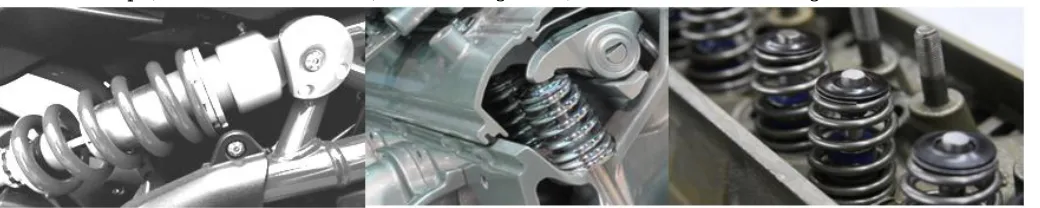
[image:2.612.42.562.290.394.2]Helical compression spring is a popular mechanism. It is being used in many applications such as for energy storage, as a shock absorber or damper, for measurement of forces, for transferring motion, etc. Some are shown in the figure 1.
Figure 1: Applications of helical compression spring
It is important to have uniformity in the spring design to obtain a smooth operation. It is observed that when an axial force is applied on the spring, the same amount of force does not transfer at the other end. There can be multiple reasons like asymmetry in the coil structure, varying diameter of wire, varying pitch, non uniform stiffness, buckling, etc. These possible causes are explained in detailed in the next section. It is understood that, some amount of applied axial force is departing in other directions, termed as side forces or lateral forces as shown in figure 2. 'R' is a vertical reaction against axial force 'F'. The additional members 'LF1' and 'LF2' are nothing but the side forces or lateral forces.
LF LF LFn
R
F 1 2 (1)
It may be assumed that the resultant of these forces may not be exactly vertical. It can treat as off center load coming out from lateral forces. It shows the scope to study the amount of lateral forces in different types of compression spring under different applications.
This paper is organized as follows: Next section presents the presents the possible causes of lateral forces. Section III presents the proof of discussion through nonlinear FEA for different cases. The last section concludes the findings.
[image:2.612.257.357.596.719.2]II. CAUSES OF LATERAL FORCES
[image:3.612.176.442.109.268.2]This section presents different possible causes of the generation of lateral forces in the helical compression spring (figure 3),
Figure 3: Causes of lateral forces in helical spring
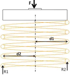
A. Asymmetry along central axis
The manufacturing defects, machining defects or material defect may cause asymmetry along central axis of helical compression
spring (d1 ≠ d2) as shown in figure 4. Further, the resultant stresses under application of axial load will be non uniform which may
lead to unwanted lateral forces.
Figure 4:Assymetry in the helical compression spring
B. Stresses in Spring
When the spring loaded axially, the deformation experience by the wire is one of pure torsion. This is illustrated in the equation 2.
2 D F T (2)
where, T: Torque, F : axial force and D : coil diameter. Equation '2' in terms of shear force can be written as,
3 1 8 d FD
(3)
In addition to the torsional shear stress induced in wire, the following stresses also act on the wire:
1) Direct shear stress due to the load 'F', and
2) Stress due to curvature of wire
The direct shear stress is given by,
2 2 4 d F
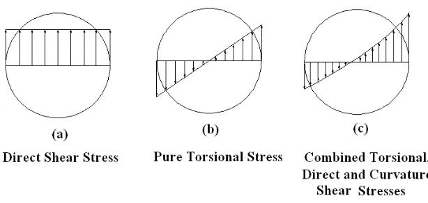
[image:3.612.257.376.347.475.2]These different stresses are shown in figure 5.
Figure 5: Stress across wire diameter of spring
The combined stresses diagram shows the non uniformity throughout the cross sectional area of the spring. It may results in unnecessary stiffness at the bottom of spring due to lateral forces.
C. Variation in Pitch
Generally a pitch at the ends is kept different to avoid Surge in the spring. The variable pitch with improper design sometime may
generate surge, which further may lead to unwanted stiffness and lateral forces.
D. Wire Diameter
If the diameter of wire used in helical compression spring is not uniform, then stresses created across cross-section will be non-uniform. Ultimately, at different cross section, there will be different deflection in spring for particular given load. This may cause non-uniformity in spring. So, due to this, there may be problem of surge or buckling in spring which may cause spring failure.
E. Eccentric Loading of Spring
Sometimes, the load on the springs does not coincide with the axis of the spring, i.e., the spring is subjected to an eccentric load. In such cases, not only the safe load for the spring reduces, the stiffness of the spring are also affected. The eccentric load on the spring increases the stress on one side of the spring and decreases on the other side. Due to this reason for applying load there will not be a proper reacting force from the bottom, which result in the generation of some lateral stiffness at the bottom.
F. Buckling in Spring
It has been found experimentally that when the free length of the spring (Lf) is more than four times the mean or pitch diameter (D),
then the spring behaves like a column and may fail by buckling at a comparatively low load. In the case of buckling, for the applied load the deflecting wave will not transfer uniformly through spring. So, along with vertical stiffness there will be generation of some lateral stiffness.
The Critical Load that causes buckling may be calculated by using the following relation,
f B
cr
k
K
L
W
*
*
(5)Where
k = Spring Rate = F/δ,
Lf = Free length of spring
Figure 6: Buckling of helical compression spring
III. ANALYSIS OF A HELICAL SPRING
Different possible causes of lateral forces in the helical compression spring are presented in the previous section. To understand the percentage of lateral force against axial load, the nonlinear FE analysis is carried out. This section mainly presents the results of the analysis.
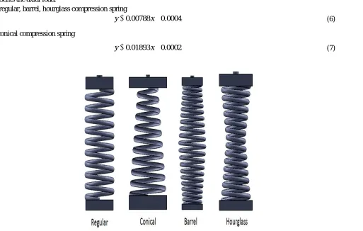
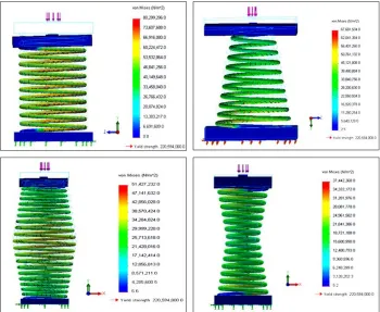
[image:5.612.61.574.399.725.2]Four different cases such as regular, conical, barrel and hourglass spring as shown in figure 7 are considered for the analysis. At one end, an axial force is applied and the other end is kept fixed. To obtain accuracy in results, high quality meshing is carried out after convergence analysis.
Figure 8 shows the analysis results. As shown in figure 9, for regular, barrel and hourglass spring the lateral forces are very much similar. In comparison, the conical compression spring shows more lateral forces. In all cases, the lateral forces are linearly proportional with applied load. The regression models are presented in equations 6 and 7. 'y' represents the lateral force while 'x' represents the axial load.
For regular, barrel, hourglass compression spring
0004 . 0 00788 .
0
x
y (6)
For conical compression spring
0002 . 0 01893 .
0
x
y (7)
[image:5.612.173.439.466.725.2]Figure 8: Nonlinear FEA results of helical compression springs
Figure 9: Lateral forces in helical compression springs
III. CONCLUSION
This paper presents the study of lateral forces in helical compression spring under application of axial load. Four different types such as regular, conical, barrel and hourglass compression spring are presented as an example case. The nonlinear FEA results present the comparative study. Conical spring produces more lateral forces comparative to other springs. The paper also presents the possible reasons for lateral forces which can be addressed to minimize it.
REFERENCES
[1] Merville K. Forrester, “Stiffness Model of a Die Spring”, MastersThesis, Balcksburg Virginia, 2001 (https://theses.lib.vt.edu/theses/available/etd-05062002-004428/unrestricted/Etd.pdf)
[2] Wahl A M, “Mechanical Springs”, 2nd Edition, McGraw Hill, Inc New York, 1978. [3] Khurmi and Gupta, “A Textbook of Machine Design”, S CHAND Publication, 2014 [4] B V Bhandari , “ Design of Machine Elements”, Tata McGraw-Hill Education, 2010
[image:6.612.192.417.391.548.2]