Technology (IJRASET)
©IJRASET 2015: All Rights are Reserved
28
Reactive Power Improvement Using STATCOM in
Wind Park Energy System
M. Anbarasi1, K. Pandia Rajan2, K.Karthikeyan3
EEE, PRIST University, Pondicherry, Tamil Nadu, India
Abstract: Large number of wind turbines are being installed and connected to power systems. In some of the countries the penetration of wind power is significant high so as to affect the power quality, system operation and control and power system stability. In this paper an attempt is made to predict the reactive power burden of the wind farm based on conventional fixed speed induction generator during wind variation and fault condition. MATLAB based large scale wind farm model is developed where STATCOM is introduced as an active voltage and reactive power supporter to increase the power system stability. STATCOM unit injects reactive power to mitigate power quality problems and to get stable grid operation.
Keywords: STATCOM, Active Voltage Support, Reactive Voltage Support.
I. INTRODUCTION
Wind power is the conversion of wind energy into a useful form of energy, such as using wind turbines to produce electrical power, windmills for mechanical power, wind pumps for water pumping or drainage, or sails to propel ships.
Large wind farms consist of hundreds of individual wind turbines which are connected to the electric power transmission network. For new constructions, onshore wind is an inexpensive source of electricity, competitive with or in many places cheaper than fossil fuel plants. Offshore wind is steadier and stronger than on land, and offshore farms have less visual impact, but construction and maintenance costs are considerably higher. Small onshore wind farms can feed some energy into the grid or provide electricity to isolated off-grid locations.
Wind power, as an alternative to fossil fuels, is plentiful, renewable, widely distributed, clean, produces no greenhouse gas emissions during operation and uses little land. The effects on the environment are generally less problematic than those from other power sources. As of 2011, Denmark is generating more than a quarter of its electricity from wind and 83 countries around the world are using wind power to supply the electricity grid. In 2010 wind energy production was over 2.5% of total worldwide electricity usage, and growing rapidly at more than 25% per annum.
Wind power is very consistent from year to year but has significant variation over shorter time scales. As the proportion of wind power in a region increases, a need to upgrade the grid and a lowered ability to supplant conventional production can occur. Power management techniques such as having excess capacity storage, geographically distributed turbines, dispatch able backing sources, storage such as pumped-storage hydroelectricity, exporting and importing power to neighboring areas or reducing demand when wind production is low, can greatly mitigate these problems.
A. Wind Farm
A wind farm or wind park is a group of wind turbines in the same location used to produce energy. A large wind farm may consist of several hundred individual wind turbines and cover an extended area of hundreds of square miles, but the land between the turbines may be used for agricultural or other purposes. A wind farm can also be located offshore.
Technology (IJRASET)
©IJRASET 2015: All Rights are Reserved
29
B. Wind Turbine Design
Fig.1 Wind turbine
Wind turbine components 1-Foundation, 2-Connection to the electric grid, 3-Tower, 4-Access ladder, 5-Wind orientation control (Yaw control), 6-Nacelle, 7-Generator, 8-Anemometer, 9-Electric or Mechanical Brake, 10-Gearbox, 11-Rotor blade, 12-Blade pitch control, 13-Rotor hub.
Wind turbine design is the process of defining the form and specifications of a wind turbine to extract energy from the wind.[1] A wind turbine installation consists of the necessary systems needed to capture the wind's energy, point the turbine into the wind, convert mechanical rotation into electrical power, and other systems to start, stop, and control the turbine.
This article covers the design of horizontal axis wind turbines (HAWT) since the majority of commercial turbines use this design. In 1919 the physicist Albert Betz showed that for a hypothetical ideal wind-energy extraction machine, the fundamental laws of conservation of mass and energy allowed no more than 16/27 (59.3%) of the kinetic energy of the wind to be captured. This Betz' law limit can be approached by modern turbine designs which may reach 70 to 80% of this theoretical limit.
In addition to aerodynamic design of the blades, design of a complete wind power system must also address design of the hub, controls, generator, supporting structure and foundation. Further design questions arise when integrating wind turbines into electrical power grids.
1) Aerodynamics: The shape and dimensions of the blades of the wind turbine are determined by the aerodynamic performance
required to efficiently extract energy from the wind, and by the strength required to resist the forces on the blade.
The aerodynamics of a horizontal-axis wind turbine are not straightforward. The air flow at the blades is not the same as the airflow far away from the turbine. The very nature of the way in which energy is extracted from the air also causes air to be deflected by the turbine. In addition the aerodynamics of a wind turbine at the rotor surface exhibit phenomena that are rarely seen in other aerodynamic fields.
In 1919 the physicist Albert Betz showed that for a hypothetical ideal wind-energy extraction machine, the fundamental laws of conservation of mass and energy allowed no more than 16/27 (59.3%) of the kinetic energy of the wind to be captured. This Betz' law limit can be approached by modern turbine designs which may reach 70 to 80% of this theoretical limit.
Technology (IJRASET)
©IJRASET 2015: All Rights are Reserved
30
square of the rotation speed, which makes this structure sensitive to over speed. Because the power of the wind increases as the cube of the wind speed, turbines have to be built to survive much higher wind loads (such as gusts of wind) than those from which they can practically generate power. Wind turbines have ways of reducing torque in high winds.
A wind turbine is designed to produce power over a range of wind speeds. All wind turbines are designed for a maximum wind speed, called the survival speed, above which they will be damaged. The survival speed of commercial wind turbines is in the range of 40 m/s (144 km/h, 89 MPH) to 72 m/s (259 km/h, 161 MPH). The most common survival speed is 60 m/s (216 km/h, 134 MPH).
If the rated wind speed is exceeded the power has to be limited. There are various ways to achieve this. A control system involves three basic elements: sensors to measure process variables, actuators to manipulate energy capture and component loading, and control algorithms to coordinate the actuators based on information gathered by the sensors.
3) Stall: Stalling works by increasing the angle at which the relative wind strikes the blades (angle of attack), and it reduces the induced drag (drag associated with lift). Stalling is simple because it can be made to happen passively (it increases automatically when the winds speed up), but it increases the cross-section of the blade face-on to the wind, and thus the ordinary drag.
A fully stalled turbine blade, when stopped, has the flat side of the blade facing directly into the wind. A fixed-speed HAWT inherently increases its angle of attack at higher wind speed as the blades speed up. A natural strategy, then, is to allow the blade to stall when the wind speed increases. This technique was successfully used on many early HAWTs. However, on some of these blade sets, it was observed that the degree of blade pitch tended to increase audible noise levels.
Fig.2 Pitch Controller
Fig.3 Flow diagram for wind turbine plant
II. PROPOSED FUNCTIONALITY
Technology (IJRASET)
©IJRASET 2015: All Rights are Reserved
31
Fig.4 Block Diagram for Proposed System
A. Converter - Based FACTS Controllers
Converter - based FACTS controllers such as the STATIC Synchronous COMPENSATOR (STATCOM), the Static Synchronous Series Compensator (SSSC), the Unified Power Flow Controller (UPFC), the Interline Power Flow Controller (IPFC), and the Generalized Unified Power Flow Controller (GUPFC) can be used to control of voltage, protect the systems against voltage collapse, enhance transient stability, and increase the damping of power system oscillations. In addition, those FACTS controllers that have series converters also have the ability to control active and reactive power flows.
III. WORKING OPERATION
The STATCOM (or SSC) is a shunt-connected reactive-power compensation device that is capable of generating and/ or absorbing reactive power and in which the output can be varied to control the specific parameters of an electric power system.
A. Need for Reactive Power Compensation
The main reason for reactive power compensation has to provide the following,
a) The voltage regulation and increased system stability b) Better utilization of machines connected to the system c) Reducing losses associated with the system
d) To prevent voltage collapse as well as voltage sag.
B. General Description of the STATCOM
A STATCOM is analogous to an ideal synchronous machine, which generates a balanced set of three sinusoidal voltages at the fundamental frequency with controllable amplitude and phase angle. STATCOM provides instantaneous control and therefore increased capacity of transmission voltage, providing the greater flexibility in bulk-power transactions, and it also increases the system reliability by damping grids of major oscillations in this grid. To summarize, a STATCOM controller provides voltage support by generating or absorbing reactive power at the point of common coupling without the need of large external reactors or capacitor banks.
C. Principle and Operation of STATCOM
Technology (IJRASET)
©IJRASET 2015: All Rights are Reserved
32
STATCOM power circuit is shown in Fig.4.1 (a), where a VSC is connected to a utility bus through magnetic coupling. In Fig. 4.1(b), a STATCOM is seen as an adjustable voltage source behind a reactance meaning that capacitor banks and shunt reactors are not needed for reactive-power generation and absorption, thereby giving a STATCOM a compact design, or small footprint, as well as low noise and low magnetic impact. The exchange of reactive power between the converter and the ac system can be controlled by varying the amplitude of the 3-phase output voltage, Es, of the converter, as illustrated in Fig. 3.1(c).
Fig.4 STATCOM Principle diagram, (a) Power Circuit, (b) Equivalent Circuit, (c) Power Exchange
D. Reactive Power Compensation
The reactive power compensation can be analyzed in two cases as shown in below
Case-I: When Vi >Vs
If the amplitude of the output voltage (Es=Vi ) is increased above that of the utility bus voltage (Et=Vs) then a current flows through the reactance from the converter to the ac system and the converter generates capacitive-reactive power for the ac system.
Fig.3.2 Reactive Power Generation
Case II: When Vi < Vs If the amplitude of the output voltage is decreased below the utility bus voltage, then the current flows
from the ac system to the converter and the converter absorbs inductive-reactive power from the ac system. Vs
Vi
Technology (IJRASET)
©IJRASET 2015: All Rights are Reserved
33
Case III: When Vi = Vs
If the output voltage equals the ac system voltage, the reactive-power exchange becomes zero, in which case the STATCOM is said to be in a floating state.
E. Real Power Compensation
Adjusting the phase shift between the converter-output voltage and the ac system voltage can similarly control real-power exchange between the converter and the ac system.
1) Real Power Generation: The converter can supply real power to the ac system from its dc energy storage if the
converter-output voltage is made to lead the ac-system voltage.
2) Real Power Absorption: It can absorb real power from the ac system for the dc system if its converter output voltage lags behind the ac-system voltage.
A STATCOM provides the desired reactive power by exchanging the instantaneous reactive power among the phases of the ac system. The mechanism by which the converter internally generates and or absorbs the reactive power can be understood by considering the relationship between the output and input powers of the converter.
The converter switches connect the dc-input circuit directly to the ac-output circuit. Thus the net instantaneous power at the ac output terminals must always be equal to the net instantaneous power at the dc-input terminals (neglecting losses). Assume that the converter is operated to supply reactive-output power. In this case, the real power provided by the dc source as input to the converter must be zero. Furthermore, because the reactive power at zero frequency (dc) is by definition zero, the dc source supplies no reactive power as input to the converter and thus clearly plays no part in the generation of reactive-output power by the converter. In other words, the converter simply interconnects the three output terminals so that the reactive-output currents can flow freely among them. If the terminals of the ac system are regarded in this context, the converter establishes a circulating reactive-power exchange among the phases.
F. Role of DC Storage Capacitor
However, the real power that the converter exchanges at its ac terminals with the ac system must, of course, be supplied to or absorbed from its dc terminals by the dc capacitor. Although reactive power is generated internally by the action of converter switches, a dc capacitor must still be connected across the input terminals of the converter. The primary need for the capacitor is to provide a circulating-current path as well as a voltage source. The magnitude of the capacitor is chosen so that the dc voltage across its terminals remains fairly constant to prevent it from contributing to the ripples in the dc current.
Technology (IJRASET)
©IJRASET 2015: All Rights are Reserved
34
The VSC has the same rated-current capability when it operates with the capacitive- or inductive-reactive current. Therefore, a VSC having a certain MVA rating gives the STATCOM twice the dynamic range in MVAR (this also contributes to a compact design). A dc capacitor bank is used to support (stabilize) the controlled dc voltage needed for the operation of the VSC. The reactive power of a STATCOM is produced by means of power-electronic equipment of the VSC type. The VSC may be a 2- level or 3-level type, depending on the required output power and voltage.
G. Flow Chart for Real and Reactive Power Compensation
[image:8.612.190.430.207.364.2]The following Flow Chart in Fig. 6 shows that the simple way of representing the both real and reactive power flows along the transmission line.
Fig.6 Flow Chart for Real Power and Reactive Power Compensation
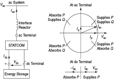
H. V-I Characteristic
A typical V-I characteristic of a STATCOM is depicted in Fig. 3.5. As can be seen, the STATCOM can supply both the capacitive and the inductive power for the compensation and is able to independently control its output current over the rated maximum capacitive or inductive range irrespective of the amount of ac-system voltage. That is, the STATCOM can provide full capacitive-reactive power at any system voltage—even as low as 0.15 pu.
Fig 7 Power Exchange Between The STATCOM and The AC System
[image:8.612.187.383.474.615.2]Technology (IJRASET)
[image:9.612.225.448.99.200.2]©IJRASET 2015: All Rights are Reserved
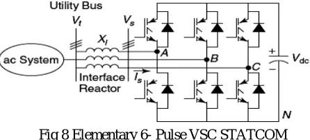
35
Fig 8 Elementary 6- Pulse VSC STATCOM
I. Application of STATCOM
a) Dynamic voltage control in transmission and distribution systems b) Power-oscillation damping in power-transmission systems c) Transient stability and Voltage flicker control
d) Control of not only reactive power but also (if needed) active power in the connected line, requiring a dc energy source.
e) It allows dispatchers to change the relative phase angle between two system voltages thereby helping them to control real power transfers between the two interconnected power systems.
f)Also attenuates the frequency of oscillations of power flow following a load disturbance in either of the areas, as well.
J. Advantages of STATCOM
a)It occupies a small footprint, for it replaces passive banks of circuit elements by compact electronic converters b)It offers modular, factory-built equipment, thereby reducing site work and commissioning time
c)It uses encapsulated electronic converters, thereby minimizing its environmental impact d)The high speed responses of phase shifters make them attractive for use in improving stability.
K. Simulation Module and Screenshots
Technology (IJRASET)
[image:10.612.192.430.93.279.2]©IJRASET 2015: All Rights are Reserved
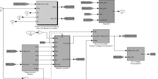
36
[image:10.612.181.415.322.449.2]Fig. 8.Simulink Model for Proposed System
Fig.9 Wind Turbine Module
IV. STATCOM
It is observed that the source current on the grid is affected due to the effects of nonlinear load and wind generator, thus purity of waveform may be lost on both sides in the system. The inverter output voltage under STATCOM operation with load variation is shown in Vabc & Iabc Output waveform. The dynamic load does affect the inverter output voltage. The source current with and without STATCOM operation is shown in Vabc & Iabc Output waveform. This shows that the unity power factor is maintained for the source power when the STATCOM is in operation
[image:10.612.196.459.585.718.2]Technology (IJRASET)
©IJRASET 2015: All Rights are Reserved
37
V. SIMULATION RESULT
A. Wind Generator
Wind generator result is shown in below scope graph all the values are in P.U (Per Unit)Rotor Speed =1.5PU is maintain constant at wind speed 8m/s.
Fig.11 Wind generator Output
B. STATCOM
STATCOM Vm,Vref & Qm,Qref Values
Fig.12 Vm,Vref & Qm,Qref
Technology (IJRASET)
©IJRASET 2015: All Rights are Reserved
38
C. Voltage Sag Mitigation
[image:12.612.80.532.135.285.2]Without Fault Voltage Sag Waveform
Fig.14 without Fault Condition Voltage (Vm) and Reactive Power (Qm)
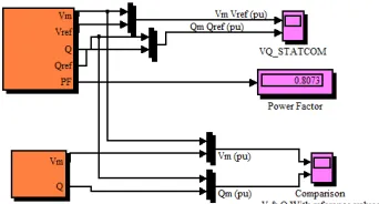
D. Power Factor
[image:12.612.228.399.350.442.2]Power factor is maintained at PF= 0.8073
Fig.15 Power Factor without fault
E. With Fault Voltage Sag Waveform
[image:12.612.80.529.493.669.2]Technology (IJRASET)
©IJRASET 2015: All Rights are Reserved
39
F. Power Factor
Power factor is maintained at PF= 0.8671
Fig.5.10 Power Factor with fault
VI. CONCLUSION
The paper presents the STATCOM-based control scheme for power quality improvement for wind energy system. The power quality issues and its consequences on the consumer and electric utility are presented. The operation of the control system developed for the STATCOM in MATLAB/Simulink for maintaining the power quality is simulated. In that readings are measure in both Fault and Normal Operation and the power factor is improved in fault condition compared to normal operation. The proposed system is efficient way mitigate the reactive power in transmission line.
REFERENCES
[1] A. Sannino, “Global power systems for sustainable development,” in IEEE General Meeting, Denver, CO, Jun. 2004
[2] K. S. Hook, Y. Liu, and S. Atcitty, “Mitigation of the wind generation integration related power quality issues by energy storage,” EPQU J.,vol. XII, no. 2, 2006. [3] R. Billinton and Y. Gao, “Energy conversion system models for adequacy assessment of generating systems incorporating wind energy,” IEEE Trans. on E. Conv., vol. 23, no. 1, pp. 163–169, 2008, Multistate.
[4] Wind Turbine Generating System—Part 21, International standard- IEC61400-21, 2001.
[5] J. Manel, “Power electronic system for grid integration of renewable energy source: A survey,” IEEE Trans. Ind. Electron., vol. 53, no. 4, pp. 1002–1014, 2006, Carrasco.
[6] M. Tsili and S. Papathanassiou, “A review of grid code technology requirements for wind turbine,” Proc. IET Renew.power gen., vol. 3, pp. 308–332, 2009. [7] S. Heier, Grid Integration of Wind Energy Conversions. Hoboken, NJ: Wiley, 2007, PP-256-259.
[8] J. J. Gutierrez, J. Ruiz, L. Leturiondo, and A. Lazkano , “Flicker Measurement system for wind turbine Certification,” IEEE Trans. Instrum. Meas., vol. 58, no. 2,pp. 375–382, Feb. 2009.
[9] Indian Wind Grid Code Draft report on, Jul. 2009, pp. 15–18, C- NET.
[10] C. Han, A. Q. Huang, M. Baran, S. Bhattacharya, and W. Litzenberger, “STATCOM impact study on the integration of a large wind farm into a weak loop power system,” IEEE Trans. Energy Conv., vol. 23, no. 1, pp. 226–232, Mar. 2008.
[11] D. L. Yao, S. S. Choi, K. J. Tseng, and T. T. Lie, “A statistical approach to the design of a dispatchable wind power—Battery energy storage system,” IEEE Trans.Energy Conv., vol. 24, no. 4, Dec. 2009.
[12] F. Zhou, G. Joos, and C. Abhey, “Voltage stability in weak connection wind farm,” in IEEE PES Gen. Meeting, 2005, vol. 2, pp. 1483–1488.
[13] T. Kinjo and T. Senjyu, “Output leveling of renewable energy by electric double layer capacitor applied for energy storage system,” IEEE Trans. Energy Conv., vol.21, no. 1, Mar. 2006.
[14] R. S. Bhatia, S. P. Jain, D. K. Jain, and B. Singh, “Battery energy storage system for power conditioning of renewable energy sources,” in Proc. Int. Conf. Power Electron Drives System, Jan. 2006, vol. 1, pp. 501–506.
[15] S. W. Mohod and M. V. Aware, “Grid power quality with variable speed wind energy conversion,” in Proc. IEEE Int. Conf. Power Electronic Drives and Energy System (PEDES), Delhi, Dec. 2006.
[16] Fu. S. Pai and S.-I. Hung, “Design and operation of power converter for microturbine powered distributed generator with capacity expansion capability,” IEEE Trans. Energy Conv., vol. 3, no. 1, pp. 110–116, Mar. 2008.
[17] J. Zeng, C. Yu, Q. Qi, and Z. Yan, “A novel hysteresis current control for active power filter with constant frequency,” Elect. Power Syst. Res., vol. 68, pp. 75– 82,2004.
[18] M. I. Milands, E. R. Cadavai, and F. B. Gonzalez, “Comparison of control strategies for shunt active power filters in three phase four wire system,” IEEE Trans. Power Electron., vol. 22, no. 1, pp. 229–236, Jan. 2007.
Technology (IJRASET)
©IJRASET 2015: All Rights are Reserved