5
VIII
August 2017
Numerical Analysis and Investigation of Fuel
Blending with Methanol, Ethanol & Gasoline on
The Performance of SI Engine
Sudhakar Singh1, Vardan Singh Nayak2 1M. Tech Scholar Mechanical Engg. Dept. VIST BHOPAL
2Asst. Professor Mechanical Engg. Dept. VIST BHOPAL
Abstract: In the study, a complete literatures review of two stroke petrol engine, operating on blends of methanol, ethanol & Gasoline is performed to two strokes and to find effects on performance. The research on alternative fuels for internal combustion engine has become essential due to depletion of petroleum products and its major contribution for pollutants, where blends of methanol, ethanol & Gasoline fuel is one of the most promising fuel alternatives for the future Physical properties relevant to the fuel were determined for the four blends of gasoline. In this study, methanol was used to increase performance and decrease emissions of a single-cylinder engine. This method is used for increasing the fuel efficiency of a vehicle by adding different percentage of methanol to the petrol and to decrease the pollutants produced during combustion process. SI engine was tested on blends containing 5%,10%,15%,20% ethanol and performance characteristics, and exhaust emissions were evaluated by CFD. Even though higher blends can replace gasoline in a SI engine, results showed that there is a reduction in exhaust gases, and increase in Brake Thermal Efficiency on blending. Due to the continuously increases in the cost of fossil fuels, demands for clean energy have also been increasing. Therefore, alternative fuels sources are sought to have alternate source for petrol without altering the existing engine or slight changes in the engine at low cost. Finally we conclude
For this complex combustion process that different kind of blending grade can be used with alternate fuels for increasing the combustion Efficiency and reducing the emissions for SI engines. Alternate fuels are very cheaper, easily available in nature and can be formed at very low cost as compare to the conventional fuels.
Keywords: Alternate fuels , blending, Gasoline, Methanol, Ethanol, CFD, Ansys (Fluent), SI Engine etc.
I. INTRODUCTION
political decisions may have to be taken to eradicate this problem in the future. Furthermore, the dwindling supply of petroleum. Today, the transport sector is a major contributor to net emissions of greenhouse gases, of which carbon dioxide is particularly important. The carbon dioxide emissions originate mainly from the use of fossil fuels; mostly gasoline and diesel oil in road transportation systems, although some originates from other types of fossil fuels such as natural gas and Liquefied Petroleum Gas (LPG) . If international and national goals (such as those set out in the Kyoto protocol) for reducing net emissions of carbon dioxide are to be met, the use of fossil fuels in the transport sector has to be substantially reduced.
A. Ethanol as a Blend
In the medium term ethanol produced from grain will probably be the most important alternative fuel for replacing gasoline and in the long term ethanol produced from cellulose might take over from grain ethanol. Today, ethanol accounts for a substantial part of the alternative fuel market. From an international perspective, most research up to 1990 was focused on blends of methanol and gasoline, but some studies were carried out on ethanol-gasoline blends. It should also be noted that for a long time 10% ethanol has been added to commercial gasoline in many parts of the world. The primary advantage of adding a bio based alcohol to gasoline is that it reduces net CO2emissions but it also has other positive effects, such as increasing the octane value of the fuel and reducing the benzene content of the exhaust gases.The International Energy Agency (IEA), established in 1974, follows the development, and data and other experience from various trials have been presented and discussed at symposia organized by the International Symposium on Alcohol Fuels (ISAF).
B. Scope and Objective of Present Work
In the present work, our objective is to increase the performance of the two stroke engine to achieve better power and emission characteristics with the latter. Due to the continuously increases in the cost of fossil fuels, demands for clean energy have also been increasing. Therefore, alternative fuels sources are sought to have alternate source for petrol without altering the existing engine or slight changes in the engine at low cost.
II. LITERATURE
Kowalewicz 1The objective of this paper is to investigate the gas flow temperature in the intake port of Four -stroke direct-injection compression ignition engine using GT-Suite software for steady-state and transient simulation. To investigate and simulate the intake port gas flow temperature profile of compression ignition engine is using GT-Power engine model were developed in this paper. GT-Power. Is sub-system menu from GT-Suite? The engine model is developed from the real compression ignition. Engine data and input to software library. In this research, the simulation of engine model is running in
vehicles have the highest penalty for increasing range, due to their heavy fuel storage systems, but are the most attractive for a 160-km range. DI engines, particularly diesels, may not be able to meet strict emissions standards, at least not without lowering efficiency.
III. OBJECTIVE OF THE STUDY
The research on alternative fuels for internal combustion engine has become essential due to depletion of petroleum products and its major contribution for pollutants, where blends of methanol, ethanol & Gasoline fuel is one of the most promising fuel alternatives for the future. Physical properties relevant to the fuel were determined for the four blends of gasoline. In this study, methanol and Ethanol was used to increase performance and decrease emissions of a single-cylinder engine. This method is used for increasing the fuel efficiency of a vehicle by adding different percentage of methanol to the conventional fuel and to decrease the pollutants produced during combustion process. SI engine will be tested on blends containing 5%,10%,15%,20% ethanol and performance characteristics, and exhaust emissions were evaluated by CFD. Ansys (Fluent14.5) is used for simulation process to find out the exact comparative study of fuels for different blending grades.
IV. METHODOLOGY A. Turbulence models
Turbulent streams are characterized by fluctuating the speed fields. These vacillations trademarks blend transported amounts like force, vitality, and species focus, and cause the shipped amounts to vary too. Since these changes can be of high recurrence and little scale, the computational expense is excessively costly, making it impossible to reenact specifically in hand building counts. Rather, the quick (correct) overseeing mathematical statements can be troupe found the middle value of, time-arrived at the midpoint of, or generally controlled to evacuate the minor scales, bringing about an adjusted arrangement of comparisons that are computationally less costly to understand. While, changed mathematical statements contain extra obscure variables, and turbulence models are required to decide these variables as far as known amounts. There are distinctive turbulence models accessible in FLUENT.
B. Basic Steps to Perform CFD Analysis
1) Pre-processing: CAD Modeling: Creation of CAD Model by using CAD modeling tools for creating the geometry of the part/assembly of which you want to perform FEA.CAD model may be 2D or 3d.
2) Meshing: Meshing is a critical operation in CFD. In this operation, the CAD geometry is discretized into large numbers of small Element and nodes. The arrangement of nodes and element in space in a proper manner is called mesh. The analysis accuracy and duration depends on the mesh size and orientations. With the increase in mesh size (increasing no. of element), the CFD analysis speed decrease but the accuracy increases.
3) Type of Solver: Choose the solver for the problem from Pressure Based and density based solver.
4) Physical model: Choose the required physical model for the problem i.e. laminar, turbulent, energy, multi-phase, etc. 5) Material Property: Choose the Material property of flowing fluid.
6) Boundary Condition: Define the desired boundary condition for the problem i.e. temperature, velocity, mass flow rate, heat flux etc.
C. Solution
1) Solution Method : Choose the Solution method to solve the problem i.e. First order, second order 2) Solution Initialization: Initialized the solution to get the initial solution for the problem.
3) Run Solution: Run the solution by giving no of iteration for solution to converge.
D. Post Processing
For viewing and interpretation of Result. The result can be viewed in various formats: graph, value, animation etc.
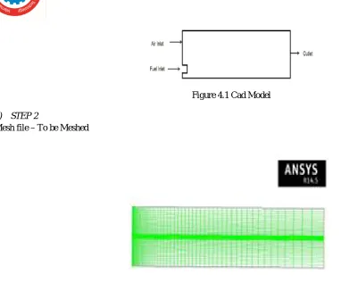
below:-Figure 4.1 Cad Model
2) STEP 2
Mesh file –To be Meshed
Figure 4.2 Mesh Model
3) Step 3 Checks The Mesh: : Various checks on the mesh and reports the progress in the console. Also check the minimum volume reported and make sure this is a positive number select mesh to mm.
a) methods- 1. Pressure based b) 3D Model is used.
c) Gravity is enabling
4) Model
a) Energy equation is enabled. b) K-Epsilon turbulence model used.
c) P-1 radiation model is used, since it is quicker to run. However DO radiation model can be used for more accurate results in typical models.
d) Finite rate / eddy dissipation in turbulence chemistry. Interactions are used for species model. e) STEP 4 Simulation Setup
E. Boundary conditions
a) Mass Flow inlet: - mass flow rate is 1 kg/s, b) Outlet – pressure based, pressure Outlet.
F. Material
1) Methanol -Gasoline
a) Fluid:- (a) Air – Methanol – Gasoli b) Air – Ethanol – Gasoli
[image:5.612.47.448.66.392.2]G. STEP 5 SOLUTIONS 1) Method
a) Coupled
b) Presto model is used
Presto model is often used for buoyant flows where velocity vector near walls may not align with the wall due to assumption of uniform pressure in the boundary layer so presto can only be used with quadrilateral or Hexahedral.
2) Meshes
Pseudo transient is enabled
a) 0.1 time scale factor of turbulent kinetic energy and turbulent dissipation rate b) Time scale factor of species and energy is 10
c) Note: - Higher time scale size is used for the energy and species equation to converge the solution in less number of iterations d) Solution Initialisation: - The solution is initialize
e) Run Calculation: - Start the calculation for 1000 iterations.
[image:6.612.204.411.414.690.2]IV. RESULTS AND CONCLUSION
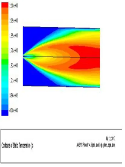
Figure 1 Static Temperature of pure Gasoline Reactants Stoichmetric
Coefficient
Rate exponent
Products Stoic metric Coefficient
Rate exponent
Fuel 1 1 CO2 1.022 0
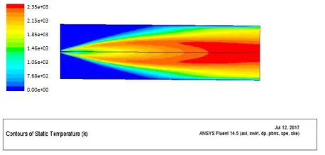
Figure 2 Static Temperature of M5 (Methanol + Ethanol + Gasoline)
[image:7.612.199.410.384.517.2]Figure 3 Static Temperature of M10 (Methanol + Ethanol + Gasoline)
Figure 4 Static Temperature of M15 (Methanol + Ethanol + Gasoline)
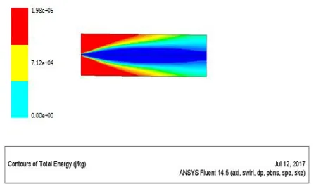
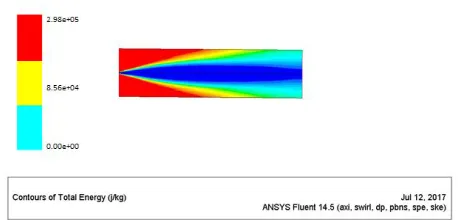
Figure 6 Total Energy of (Pure Gasoline)
Figure 7 Total Energy of M5 (Methanol + Ethanol + Gasoline)
Figure 8 Total Energy of M10 (Methanol + Ethanol + Gasoline)
[image:8.612.191.422.525.690.2]Figure 10 Total Energy of M20 (Methanol + Ethanol + Gasoline)
Figure 11 Mass fraction of CO2 (Gasoline)
[image:9.612.189.418.100.210.2]Figure 12 Mass fraction of CO2 (M5)
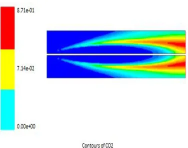
Figure 14 Mass fraction of CO2 (M15)
Figure 15 Mass fraction of CO2 (M20)
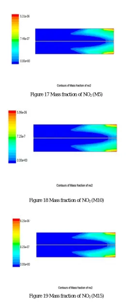
[image:10.612.200.405.542.652.2]Figure 17 Mass fraction of NO2 (M5)
[image:11.612.169.450.79.704.2]Figure 18 Mass fraction of NO2 (M10)
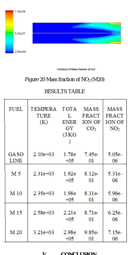
Figure 20 Mass fraction of NO2 (M20)
RESULTS TABLE
V. CONCLUSION
In present study we used a CFD tool Fluent 14.5 for solve the complex problem of fuel blending for different Grade like M5, M10, M15 and M20 with Gasoline. Alternate fuels like Methanol and Ethanol are taken for blending with gasoline which is cheaper as per cost and easily available. CFD Simulation results show a excellent flow phenomenon over the entire combustion process and flow system is stable in nature which is required in CFD simulation for accurate results. From CFD results we can conclude the following points:
A. Simulation results show a stable flow phenomenon which is required in CFD method for accuracy of flow system and authenticity of results.
B. Temperature is increasing with increased percentages of alternative fuels in gasoline that shows combustion rate is getting higher from Gasoline to M5-M20, which means efficiency of fuels is increasing with higher blending grade
D. Emissions percentages of COX and NOX is continuous decreasing while we go from M5 to M20.
Finally we conclude for this complex combustion process that different kind of blending grade can be used with alternate fuels for increasing the combustion efficiency and reducing the emissions for SI engines. Alternate fuels are very cheaper, easily available in nature and can be formed at very low cost as compare to the conventional fuels.
REFERENCES
[1] Kowalewicz, Andrzej., 1984.Combustion System of High-Speed Piston I.C. Engines, WydawnictwaKomunikacjiiLacznosci, Warszawa. [2] Stone, Richard., 1997. Introduction to Internal Combustion Engines 2ndEdition, SAE Inc., USA.
[3] Poulton, M.L., 1994. Alternative Fuels for Road Vehicles, Comp. Mechanics Publications, UK.
[4] Shashikantha., Parikh P.P., 1999. Spark ignition producer gas engine and dedicated compressed natural gas engine-Technology development and experimental performance optimization, SAE Technical Paper 1999-01-3515
[5] . Hotta,Y., 1997. Combustion improvement for reducing exhaust emissions in IDI diesel engine, JSAE Review 18, pp. 19-31
[6] Heffel, W.James., 2003. NOx emission reduction in a hydrogen fueled internal combustion engine at 3000 rpm using exhaust gas recirculation, International Journal of Hydrogen Energy 28, pp. 1285-1292.
[7] Y. Barakat Fuel consumption of gasoline ethanol blendsat different engine rotational speedsEgyptian Journal of Petroleum (2016) 25, 309–315
[8] Ashraf Elfasakhany Investigations on the effects of ethanolmethanolgasoline blends ina spark-ignition engine: Performance and emissions analysis Engineering Science and Technology, an International Journal 18 (2015) 713e719
[9] XiaochenWang The effects of hydrous ethanol gasoline on combustion and emission characteristics of a port injection gasoline engine Case StudiesinThermalEngineering6(2015)147–154
[10] Obed M. Ali Comparison Of The Effect Of Different Alcohol Additives With Blended Fuel On Cyclic Variation In Diesel Engine Energy Procedia 75 ( 2015 ) 2357 – 2362
[11] Anuj V. Kulkarni Working, Advantages of Green Engine andDevelopment Using CNGIC Value: 13.98 Volume 4 Issue V, May 2016 ISSN: 2321-9653 [12] R. A. Bakar Green Engines Development Using Compressed Natural Gas as an Alternative Fuel: A Review American Journal of Environmental Sciences 5
(3): 371-381, 2009 ISSN 1553-345X\
[13] K. Karimi Developments in Diesel Spray Characterisation and Modelling THIESEL 2006 Conference on Thermo- and Fluid Dynamic Processes in Diesel Engines
[14] Abhay Tiwari, Converting a Diesel Engine to Dual-Fuel Engine Using Natural Gas International Journal of Energy Science and Engineering Vol. 1, No. 5, 2015, pp. 163-169