© 2017, IRJET | Impact Factor value: 5.181 | ISO 9001:2008 Certified Journal
| Page 1461
MODAL ANALYSIS OF MULTISTOREY RECTANGULAR BUILDINGS WITH
1:2:2.5 PLAN RATIOS
Geetha D
1Department Of Civil Engineering, Karunya University, TamilNadu, India
---***---Abstract -
The natural frequencies and mode shapes are important parameters in the evaluation of design loads for buildings subjected to dynamic loading condition. They are also required for spectrum analysis or a mode superposition harmonics or transient analysis. In the present study, the effect of bay width on the fundamental time period of 30 storey tall rectangular buildings (1:2 side ratios in plan) with Moment Resisting Frame is studied. Free vibration analysis of the rectangular buildings is carried out to get the dynamic characteristics of the structure in terms of natural frequencies and mode shapes. In the present study, number storeys of 30 and storey height of 3.28 m are considered to be constant to study the influence of bay width of Moment Resisting Frame on the fundamental Time period and fundamental natural frequency (1st sway mode) of the building. The free vibration analysis of the building is carried out by using STAAD Pro.Key Words: NATURAL FREQUENCY, TIME PERIOD, BAY
WIDTH, FREE VIBRATION ANALYSIS, MOMENT RESISTING FRAME
.
1. INTRODUCTION ( Size 11 , cambria font)
Framed structure is most widely used structural system in building practice. The design of tall building and structure are governed by lateral loads such as wind load and seismic load. Since, the wind loads and seismic loads are dynamic in nature; the proximity of natural frequencies of tall buildings to these dynamic loads can cause resonance effects. To consider these dynamic effects due to wind and seismic loads on design of tall buildings, the natural frequency of the building is required for the evaluation of design loads. Both IS: 875 (Part 3) and IS: 1893 (Part 1) provide empirical expressions for the evaluation of fundamental time periods of tall building. In the case of Moment Resisting Frames without brick infill panels, without bracings/shear walls, the empirical expressions are observed to be function of either number of storeys (IS: 875(Part 3)) or the height of the building (IS: 1893 (Part 1)) only as highlighted in the following sections.
1.1
IS: 875 (Part 3) – 1987
IS: 875 (Part 3) – 1987 provides empirical expressions for the evaluation of fundamental time period under Note 1 of Clause 7.1 as given below:
(a) For moment resisting frames without bracing or shear walls for resisting the lateral loads
T = 0.1 n
Where n = number of storeys including basement storeys; and
(b) For all others
Where,
H = total height of the main structure of the building in metres, and
d = maximum base dimension of building in metres in a direction
Parallel to the applied wind force.”
The calculated time period of the building is used to evaluate the natural frequency, (fo =1/T), which is used to obtain Gust
Factor as provided under Clause 8.3 of IS: 875 (Part 3) – 1987 and as indicated below:
G = Gust factor (Peak Load / Mean Load) and it is given,
© 2017, IRJET | Impact Factor value: 5.181 | ISO 9001:2008 Certified Journal
| Page 1462
Chart-1: Size Reduction Factor (Fig. 10 of IS: 875 (Part 3) - 1987)
Chart-2:Gust Energy Factor (Fig. 11 of IS: 875 (Part 3) – 1987)
1.2 IS: 1893 (Part 1) – 2002
IS: 1893 (Part 1) – 2002 provides empirical expressions for the evaluation of fundamental time period under Clause 7.6 as given below:
Fundamental Natural Period
The approximate fundamental natural period of vibration (Ta), in seconds, of a moment-resisting frame building without brick infill panels may be estimated by the empirical expression:
Ta = 0.075 for RC frame building = 0.085 for steel frame building Where,
h = Height of building, in m. This excludes the basement storeys, where basement walls are connected with the ground floor deck or fitted between the building columns.
But, it includes the basement storeys, when they are not so connected.
The approximate fundamental natural period of vibration (Ta), in seconds, of all other buildings, including moment-resisting frame buildings with brick infill panels, may be estimated by the empirical expression:
Where,
h = Height of building, in m, and
d = Base dimension of the building at the plinth level, in m, along the considered direction of the lateral force.”
The calculated time period of the building is used to obtain (Sa/g) as provided in empirical expressions for (Sa/g) under
Clause 6.4.5 and in Fig. 2 of IS:1893 (Part 1) – 2002 and as indicated below:
Chart-3: Spectral Acceleration Coefficient (Fig. 2 of IS: 1893 (Part 1) – 2002)
2. FREE VIBRATION ANALYSIS OF RECTANGULAR
BUILDING
The natural frequencies and mode shapes of buildings are considered in the evaluation of design load for buildings subjected to dynamic loading conditions. Free vibration analysis of buildings is carried out to get the dynamic characteristics of the building in terms of natural frequencies and mode shapes, which are used for the computation of dynamic responses.
© 2017, IRJET | Impact Factor value: 5.181 | ISO 9001:2008 Certified Journal
| Page 1463
2.1 Modeling of building
The following are steps involved in the Finite Element Modeling of the building:
Creation of members (beams, columns and slabs)
Assigning material properties
Assigning member properties
Support specifications
Adding load cases
Building frame model was created by using following typical plan requirement:
Plan dimension : 40 m x 80 m (for Building 1)
: 60 m x 120 m (for Building 2)
Height of the building: 98.4m , Typical Bay width: 4m,
Storey height: 3.28m, No. of Storeys : 30
2.2 Output File
The calculated natural frequencies for Building 1 are given below
Table -1: Output viewer from STAAD Pro
3.
RESULTS AND DISCUSSIONS
In the present study, the influence of bay width on the natural frequencies of two tall buildings with 1:2 side ratios in plan is studied. In the present study the fundamental frequency of the building for sway mode in X and Z directions are considered. The following values are
considered constant while varying the bay width of the frame in X-direction and Z-direction in plan:
No. of Storeys = 30, Storey height = 3.28m,
Column size = 0.6x0.6m, Beam size = 0.25x0.45m.
Building 1
For Building 1, the following building dimensions in plan have been chosen: 40 m(in X-direction) x 80 m (in Z-direction).
Varying Bay width in X-direction (Case 1)
In this case, the bay width of the frame in X-direction is varied between 4 m and 10 m while keeping the bay width in Z-direction as constant as 4 m.
Varying Bay width in Z-direction (Case 2)
In this case, the bay width of the frame in Z-direction is varied between 4 m and 10 m while keeping the bay width in X-direction as constant as 4 m.
Varying Equal Bay widths in X-direction and Z-direction (Case 3)
In this case, the bay width of the frame in both X-direction and Z-direction is varied between 4m and 10m.
Building 2
For Building 2, the following building dimensions in plan have been chosen: 60 m (in X-direction) x 120 m (in Z-direction).
Varying Bay width in X-direction (Case 1)
© 2017, IRJET | Impact Factor value: 5.181 | ISO 9001:2008 Certified Journal
| Page 1464
Varying Bay width in Z-direction (Case 2)
In this case, the bay width of the frame in Z-direction is varied between 3 m and 10 m whilekeeping the bay width in X-direction as constant as 4 m.
Varying Equal Bay widths in X-direction and Z-direction (Case 3)
In this case, the bay width of the frame in both X-direction and Z-direction is varied between 3 m and 10 m.
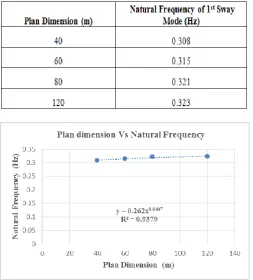
3.1 INFLUENCE OF BUILDING PLAN DIMENSION
ON NATURAL FREQUENCY
Further, the influence of building plan dimension on
natural frequency of 1
stsway mode of the building
[image:4.595.36.290.378.659.2] [image:4.595.308.560.472.749.2]has been studied.
Table 2-Natural frequency values (Hz) for Plan dimension. (For reference case ie. Equal Bay width of 4 m in both directions)
Chart -4: Comparison of Natural Frequency values for plan dimension
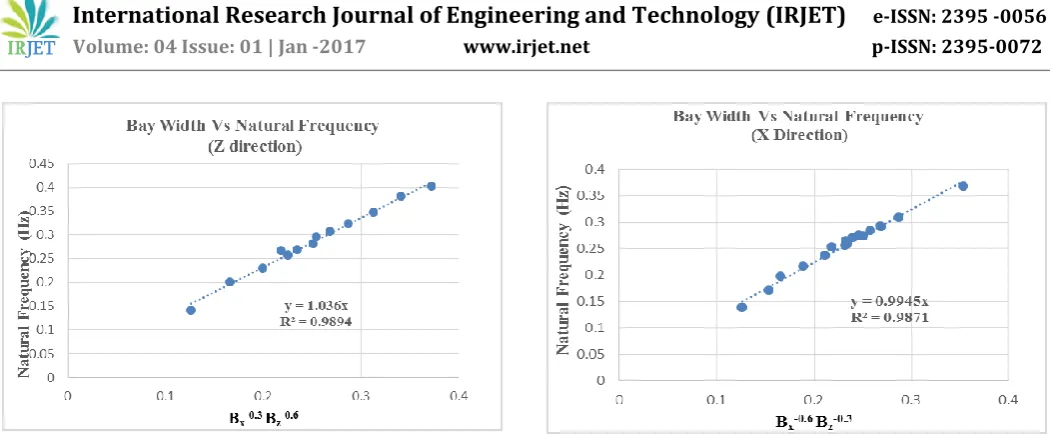
3.2 REGRESSION ANALYSIS OF RESULTS
Based on the variation of the natural frequency (1st sway
mode) of the building in a particular direction with respect to the bay width in the same direction of sway mode and the bay width in the perpendicular direction of sway mode, the following relationship has been formulated based on regression analysis carried out by using the all the values of natural frequency of 1st sway mode in
X-direction and Z-X-direction from cases 1 to 3 of Building 1 and Building 2,
Where
nx = Natural frequency of building 1st sway mode in
X-direction
nz = Natural frequency of building 1st sway mode in
Z-direction
Bx = Bay width of frame of building in X-direction
Bz = Bay width of frame of building in Z-direction
© 2017, IRJET | Impact Factor value: 5.181 | ISO 9001:2008 Certified Journal
| Page 1465
Chart -5: Variation of Natural Frequency values of 1st
[image:5.595.35.563.48.265.2]sway mode in Z-direction for Building 2
Table 3-Bay widths and Natural Frequency values for
Building 1
Chart -6: Variation of Natural Frequency values of 1st
sway mode in X-direction for Building 1
.
4. CONCLUSIONS
In the present study, the effect of bay width on the fundamental time period of two 30 storey tall rectangular buildings (1:2 side ratio in plan) with Moment Resisting Frame is studied. With a storey height of 3.28 m, the total height of both the buildings is 98.4 m. The plan dimensions of the two rectangular buildings are 40 m x 80 m for Building 1 and 60 m x 120 m for Building 2. The modal analysis of the buildings with Moment Resisting Frames without infill has been carried out using STAAD PRO software by using BEAM and PLATE elements to model beams, columns and slabs. For both the buildings, three cases of bay width variation is carried out to study their effect on the natural frequency of 1st sway mode of the building in X-direction and Z-direction
as given below:
Case 1: In X-direction: Bay width (Bx) is varied between 4 m
and 10 mfor Building 1 and between 3 m and 10 m for Building 2 while bay width in Z-direction (Bz) is kept constant of 4 m.
Case 2: In Z-direction: Bay width (Bz) is varied between 4 m
and 10 m for Building 1 and between 3 m and 10 m for Building 2 while bay width in X-direction (Bx) is kept constant of 4 m.
Case 3: In both X-direction and Z-direction: Bay widths (Bx
and Bz) are varied between 4 m and 10 m for
Building 1 and between 3 m and 10 m for Building 2.
© 2017, IRJET | Impact Factor value: 5.181 | ISO 9001:2008 Certified Journal
| Page 1466
natural frequency of the building for 1st sway mode in X and
Z direction (in plan) are studied.
Based on the modal analysis and the results obtained, the following observations have been made:
i) For constant Bz, natural frequency of 1st sway mode of the
building in X-direction is proportional to Bx-0.5. Whereas
natural frequency of 1st sway mode of the building in
Z-direction is proportional to Bx-0.2.
ii) For constant Bx, natural frequency of 1st sway mode of the
building in X-direction is proportional to Bz-0.2. Whereas
natural frequency of 1st sway mode of the building in
Z-direction is proportional to Bz-0.5.
iii) For equal bay width case of Bx = Bz = B, both natural
frequencies of 1st sway mode of the building in X-direction
and Z-direction are proportional to B-0.9.
iv) Based on regression analysis of the relationship between natural frequencies (nx and nz) and bay widths (Bx and Bz),
the following relations have been obtained:
v) Further, the influence of building plan dimensions on the natural frequency of 1st sway mode is observed to be less
than the influence of bay width.
ACKNOWLEDGEMENT
At the outset I express my gratitude to the ALMIGHTY GOD who has been with me during each and every step that I have taken towards the completion of this project.
I thank our beloved founder Late Dr. D.G.S Dhinakaran and our Honorable Chancellor Dr. Paul Dhinakaran for providing me the educative infrastructure and learning ambience, which motivated me to a greater extent.
I wish to thank with deep sense of gratitude to the management of Karunya University and to our Vice Chancellor Dr. S. SUNDAR MANOHARAN and our respected registrar Dr. C. JOSEPH KENNADDY for extending all facilities.
I express my sincere thanks to Director Dr. D. TENSING, School of Civil Engineering for his full support and valuable guidance.
I express my sincere gratitude to my internal guide Dr. G HEMALATHA, Head of Department, School of Civil Engineering, for her wholehearted support right from the beginning for successful completion of this project.
I am grateful to Dr. NAGESH R IYER, Director, Structural Engineering Research Centre (SERC) and Dr. P HariKrishna, Senior Principal Scientist and my project leader, Wind Engineering Lab to take up the Project.
My Sincere thanks to D. S SELVIRAJAN, Head of Wind Engineering Lab for her guidance and suggestion for my project.
This project would not have been completed in full shape without the efforts taken by Mr. A JOSEPH ANDREW PRASAN (Project Assistant) at SERC including various testing laboratories and civil engineering staffs of Karunya University and thank them profusely.
I would also like to thank my Beloved Parents and all my Friends who prayed and helped during the project work.
REFERENCES
1. Tall Building Structure: Analysis and Design – Bryan Stafford Smith, Mc Bill University, Canada. Alex Coull, University of Glasgow, United Kingdom.
2. Wind and Earthquake Resistance Buildings Structural Analysis And Design - BUNGALE S. TARANATH Ph.D., S.E. John A. Martin & Associates, Inc. Los Angeles, California.
3. Crawford.R and Ward.H.S (1964) “Determination of the natural periods building” Bulletin of the Seismological Society of America.
4. Li-Ling Hong,s and Woei-Luen Hwangt “Empirical formula for fundamental vibration periods of reinforced concrete buildings in Taiwan”
5. Pekau.A, Zielinski.Z.A and Lin.L (1995) “Displacement and Natural Frequencies of tall building structures by finite story Method” Department of Civil Engineering, Concordia University, Montreal, Canada.
6. Q. S. Li and J. R. Wu (2004) “Correlation of dynamic characteristics of a super-tall building from full-scale measurements and numerical analysis with various finite element models.
7. IS: 875 (Part 3) – 1987