© 2016, IRJET | Impact Factor value: 4.45 | ISO 9001:2008 Certified Journal | Page 223
Development of vibration control for chatter suppression in
Application of boring bar
Kulkarni M.D.
1Prof. R.S.Jamgekar
21P.G.Student, Department of Mechanical Engineering, BIGCE Solapur
2H.O.D. & P.G. Co-ordinator, Department of Mechanical Engineering, BIGCE Solapur
---***---Abstract - Boring, also called as internal turning operation
is the operation of enlarging the previously drilled hole. But, as the overhang increases this results deflection of boring bar which results in the vibration between a tool and a work piece. Vibration degrade the work piece surface quality as well as shorten the tool life. In this dissertation work passive damper (i.e .Nylon and PTFE) is used to suppress vibrations of boring bar and to improve the surface finish of the work piece as well as to increase useful life of the boring tool or boring bar. The experiments for boring operation are carried out on lathe by using boring tool with and without passive damper. The analysis is carried out using FFT analyzer. The machining parameters like spindle speed, feed and depth of cut are varied accordingly. The results i.e RMS value and surface roughness value Ra value are compared by using boring bar with and without damper. To determine natural frequencies and mode shape Modal analysis is also carried out.Key Words: Boring bar, passive damper, static stiffness, Vibration, Deflection, RMS Value, Modal analysis, FFT Analyzer, PTFE, Nylon, Surface Roughness
1.INTRODUCTION
Boring operation uses cantilevered (i.e overhang ) tooling which is less rigid than the tooling used for external turning. While machining deep hole it become necessary to use a tool with large length to diameter ratio. As this overhang increases this results deflection of boring bar which results in the vibration between a tool and a work piece. Vibration degrade the work
piece surface quality as well as shorten the tool life. There are several ways that can be established by the
different methods such as Active damping system, passive damping system or semi active damping system for the stability of that boring bar. By using this damping system the vibration from boring bar minimizes or reduces.
The objective of the vibration attenuation is to improve the dynamic stiffness of the machine tool structure, to increase the rate of material removal and thereby prolonging the life of the tool tip. Hence, it is important
to limit vibrations of the machine tool structure as their presence results in poor surface finish, cutting edge damage, and irritating noise.
2. METHODOLOGY 2.1 Passive damper:-.
The boring bar is held in the tool post at one end and the remaining part is called as Overhang. Some length of the boring bar from carbide insert tip is known as cutting zone which cannot be damped. Thus, the remaining length in between the cutting zone length and that held in tool post needs to be damped. The cross-section of the passive vibration damper is thus of 20.2 mm inner diameter and 25.0 mm outer diameter. The length of passive vibration damper is divided into two parts of the overhang. i.e. 30% and 60% of the overhang. In this experiment, the overhang is divided into two parts viz. 120mm and 160mm of the boring bar. Hence, 30% and 60% of 120 mm means two dampers of 36mm and 72mm are developed. Also, 30% and 60% of 160mm means two dampers of 48mm and 96mm are developed. Thus, there are four possible lengths of a passive vibration damper for one material.In our experiment, we have selected two materials for the development of passive vibration damper. They are:
1. Nylon
2. PTFE (Teflon)
© 2016, IRJET | Impact Factor value: 4.45 | ISO 9001:2008 Certified Journal | Page 224
Various grades of steels are in all types of industries by considering their wide range of applications, carbon steel work pieces made from AISI 1062 were used during experimentation. The cutting trials were conducted on pre-machined commonly found sizes cylinders of outside diameter 113 mm, inside diameter 93 mm and length approximately of 59 mm. Twenty four such work-pieces were kept pre-machined and used during the various trials shows some of these samples and Table gives the chemical of AISI 1062steel.
Before machining. After machining
Fig-1. Work pieces Before And After machining
Fig- 2. Drafting Image of AISI1062 Carbon Steel After Machining
Table- 1 Chemical Composition Of AISI 1062 Carbon Steel
C Si Mn S P
0.55 –
0.65 0.5 0.7≤1 0.05 0.04
2.2 Boring bar :-
The boring bar used in these experiments is Sandvik A20S-SCLCR 09 with through coolant .This boring bar when held in the tool post acts as a cantilever beam
during the boring operation
.
2
.3 ExperimentalProcedure:-In this Project work a passive damper is used to investigate the performance of boring tool under vibratory conditions. The experiments for boring operation are carried out using boring tool with and without passive damper. The frequency domain analysis is carried out using FFT analyzer. The
machining parameters are varied by changing spindle speed, feed rate and depth of cut.
The boring operations were carried out on a lathe machine. The work piece was mounted in a chuck. The
Fig- 3:- Experimental setup
© 2016, IRJET | Impact Factor value: 4.45 | ISO 9001:2008 Certified Journal | Page 225
1. The Fast Fourier Transform(FFT) analyser is
connected to the computer and accelerometer.
2. The passive vibration damper is inserted onto
the boring bar according to the overhang.
3.
This boring bar is then fitted in the tool postaccording to the overhang
.
4. The accelerometer is the placed as near
possible to the cutting zone so as to obtain the maximum accurate readings.
5. The workpiece is held in the chuck and made to
rotate according to the speed ( low and high) .
6. The carbide insert is then made to touch the
inner surface of the workpiece. The initial jerk is neglected and readings for the remaining operation are recorded by the software with the help of accelerometer
2.4 Testing condition
Table- 2
Testing Parameters
Table -3 Test Matrix
Run No.
Factors
A B C D E
1 1 1 1 1 1
2 2 2 1 1 1
3 1 1 1 2 2
4 2 2 1 2 2
5 1 2 2 2 1
6 2 1 2 2 1
7 1 2 2 1 2
8 2 1 2 1 2
2.5 Results
Table -4
RMS Value Of Acceleration
Table -5 Ra Value Of Surface Roughness
Run
No. Surface Roughness Ra (μm)
Nylon
Damper Damper PTFE Without damper
1 3.78 3.17 5.83
2 3.12 3.34 6.23
3 3.68 3.82 6.78
4 3.16 3.92 6.94
5 3.77 3.98 6.62
6 4.27 4.05 7.16
7 3.46 3.27 6.81
8 4.13 4.59 5.97
Sr.
No. Parameter Level
1 2
1 Spindle Speed - N
(rpm)
A 140 200
2 Feed Rate - f
(mm/rev) B 0.04 0.08
3 Depth of Cut – t
(mm)
C 0.5 1.5
4 Boring Bar
Overhang – L (mm)
D
120 160
5 Damper Length - l
(mm)
E 0.3 L 0.6 L
Run No. Overall levels RMS value (m/sec2)
Nylon Damper
PTFE Damper
Without damper
1 171 54.5 377.8
2 80.6 81.3 382.2
3 169.8 179.4 411.5
4 150.3 170.3 477.8
5 187.7 215.6 411.5
6 388.3 267.8 577
7 166 129.5 436.5
© 2016, IRJET | Impact Factor value: 4.45 | ISO 9001:2008 Certified Journal | Page 226 Chart -1 Run No. 4 Without Damper
0 200 400 600 800 1 k
Frequency (Hz) A c c e ler a tion ( m / s ² ) 10 20 30 40 50 1
Marker4 ( 745.625 Hz: 445.9 mm/s² ) 2
Marker5 ( 753.125 Hz: 364.8 mm/s² ) 3
Marker4 ( 420.938 Hz: 5.54 m/s² )
4
Marker6 ( 851.25 Hz: 596 mm/s² ) 5
Marker5 ( 389.063 Hz: 21.85 m/s² )
12 Display
Mode: Magnitude Traces:
FFT1: AvSpc [1]-Input 1 Overall levels:
Free marker
Id Label Trace X Y
1Marker4AvSpc [1] 2 Marker5AvSpc [1] 3 Marker4AvSpc [1] 4 Marker6AvSpc [1] 5 Marker5AvSpc [1] Cursor1 X: AvSpc [1] Y: Cursor2 X: AvSpc [1] Y: dX: AvSpc [1] dY:
(1:34:56 PM 11/29/2016)
RMS : 150.3 m/s²
745.625 Hz 445.9 mm/s² 753.125 Hz 364.8 mm/s² 420.938 Hz 5.54 m/s² 851.25 Hz 596 mm/s² 389.063 Hz 21.85 m/s²
1.5625 Hz 23.51 m/s² Cursor2 0 Hz 16.41 m/s² -1.5625 Hz -7.1 m/s² Display Mode: Magnitude Traces:
FFT1: AvSpc [1]-Input 1 Overall levels:
Free marker
Id Label Trace X Y
1 Marker4 AvSpc [1] 2 Marker5 AvSpc [1] 3 Marker4 AvSpc [1] 4 Marker6 AvSpc [1] 5 Marker5 AvSpc [1] Cursor1 X: AvSpc [1] Y: Cursor2 X: AvSpc [1] Y: dX: AvSpc [1] dY:
(1:34:56 PM 11/29/2016)
RMS : 150.3 m/s²
745.625 Hz 445.9 mm/s² 753.125 Hz 364.8 mm/s² 420.938 Hz 5.54 m/s² 851.25 Hz 596 mm/s² 389.063 Hz 21.85 m/s²
1.5625 Hz 23.51 m/s² Cursor2 0 Hz 16.41 m/s² -1.5625 Hz -7.1 m/s² Chart -2 Run No. 4 With Nylon damper
0 200 400 600 800 1 k
Frequency (Hz) A c c e ler a tion ( m / s ² ) 5 10 15 20 25 30 35 40 1
Marker5 ( 413.438 Hz: 33.83 m/s² ) 2
Marker2 ( 420.938 Hz: 16.25 m/s² ) 3
Marker3 ( 389.063 Hz: 3.796 m/s² )
12 Display
Mode: Magnitude Traces:
FFT1: AvSpc [1]-Input 1 Overall levels:
Free marker
Id Label Trace X Y
1Marker5AvSpc [1] 2 Marker2AvSpc [1] 3 Marker3AvSpc [1] Cursor1 X: AvSpc [1] Y: Cursor2 X: AvSpc [1] Y: dX: AvSpc [1] dY:
(2:36:08 PM 11/29/2016)
RMS : 170.3 m/s²
413.438 Hz 33.83 m/s² 420.938 Hz 16.25 m/s² 389.063 Hz 3.796 m/s²
1.5625 Hz 18.37 m/s² Cursor2 1.5625 Hz 18.37 m/s² 0 Hz 0 m/s² Display Mode: Magnitude Traces:
FFT1: AvSpc [1]-Input 1 Overall levels:
Free marker
Id Label Trace X Y
1 Marker5 AvSpc [1] 2 Marker2 AvSpc [1] 3 Marker3 AvSpc [1] Cursor1 X: AvSpc [1] Y: Cursor2 X: AvSpc [1] Y: dX: AvSpc [1] dY:
(2:36:08 PM 11/29/2016)
RMS : 170.3 m/s²
413.438 Hz 33.83 m/s² 420.938 Hz 16.25 m/s² 389.063 Hz 3.796 m/s²
1.5625 Hz 18.37 m/s² Cursor2 1.5625 Hz 18.37 m/s² 0 Hz 0 m/s²
Chart -3 Run No. 4 With PTFE damper
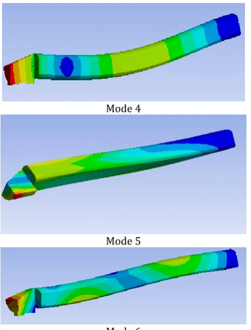
3.MODAL ANALYSIS
It is used to determine the natural frequencies and mode shapes of the structure. The natural frequencies and mode shapes are important in the design of a structure for dynamic loading conditions. A modal analysis is a technique used to determine the vibration characteristics of structures:
1) Natural frequencies– at what frequencies the structure would tend to naturally vibrate.
2)Mode shapes–In what shape the structure would tend to vibrate at each frequency.
Modal analysis is performed on Ansys software
3.1Steps in modal analysis:-
1. Creating 3D Geometry: 3D geometry is created by using CAD software.
2. Element selection: According to the size and shape of the geometry 3D element is selected.
3. Material properties: Given material properties are applied to the geometry.
4. Meshing: Meshing of the geometry as per required quality criteria.
5. Boundary conditions:-Boundary conditions are applied as per given in the design inputs.
6. solving equations
7. Post processing Reviewing results.
Fig -4 : Natural Frequencies
Mode 1
Mode 2
© 2016, IRJET | Impact Factor value: 4.45 | ISO 9001:2008 Certified Journal | Page 227
Mode 4
Mode 5
[image:5.595.39.288.109.436.2]Mode 6
Fig -5 : Mode shapes
4. CONCLUSIONS
1) From the experimental analysis it is clear that by using passive damper vibration of boring bar is reduced which result in good surface finish.
2) From modal analysis it is clear that at a higher natural frequencies above 1500 Hz boring bar will undergo bending and twisting.
5.FUTURE SCOPE
FEA Analysis of passive damper can be carried out to see the stress distribution and also one can use different materials as passive damper to check the effectiveness of passive damping.
ACKNOWLEDGEMENT
I am very thankful to my project guide Prof. R. S. Jamgekar H.O.D.& P.G. Coordinator, Mechanical Engineering Department, BIGCE College ,Solapur ,for his continuous support and encouragement in completing this work
REFERENCES
[1] Lorenzo Daghini, Andreas Archenti, and Cornel Mihai Nicolescu, 2009, ―Design, Implementation and Analysis of Composite Material Dampers for Turning Operations, World Academy of Science, Engineering and Technology 53 2009
[2] R.Kulgod, T.A.Jadhav “Analysis of a Boring Bar Using Polymer Based Composite as a Passive Damper” International Engineering Research Journal (IERJ) Special Issue 2 Page 365-371, 2015, ISSN 2395-1621
[3] M.H. Miguelez, L.Rubio, J.A.Loya, J.Fernandez-Saez, 2010,'' Improvement of chatter stability in boring operations with passive vibration absorbers '' , International Journal of Mechanical Sciences 52 (2010) 1376–1384
[4] Pranali Khatake1, P. T. Nitnaware, Vibration mitigation using passive damper in machining, International Journal of Modern Engineering Research (IJMER), 2013, 3( 6),pp-3649-3652
[5] Gaurav Saindane, Amit Jakikore, Asst. Prof. Ashish Umbarkar, Experimental Investigation of VibrationDamping in Boring Operation using Passive Damper,IJREAT International Journal of Research in Engineering & Advanced Technology, Volume 2, Issue 3, June-July, 2014ISSN: 2320 – 8791
[6] Shrikant Waydande, Prof. D. A. Mahajan Prof.(Dr.) S. Y.Gajjal, Experimental Analysis of Boring Tool Vibrations Fitted with Passive Dampers ,International Conference on Multidisciplinary Research & Practice,