© 2017, IRJET | Impact Factor value: 5.181 | ISO 9001:2008 Certified Journal | Page 1611
AC to AC STEP DOWN CYCLOCONVERTER
Viren Patel
1, Dipak Makawana
2, Vishal Rangpara
3, Jaydipsinh Zala
41.2.3
B.E. in Electrical Engineering, DSTC, Junagadh, Gujarat, India
4
Assistant Professor, Department of Electrical Engineering, DSTC, Junagadh, Gujarat, India
---***---Abstract -
To control the speed of a single phase inductionmotor in three steps using SCR based single phase cycloconverter technique. A.C. motors have great advantages of being relatively inexpensive and very reliable. The induction motors in particular are very robust. Therefore they are used in many domestic appliances such as washing machines, vacuum cleaners, water pumps, and in industries as well. Induction motor is known as constant speed machine. The difficulty of varying its speed by a cost effective device is one of its main disadvantage. As AC supply frequency cannot be changed, so this uses a thyristor controlled cycloconverter which enables control of speed in steps for an induction motor. The microcontroller used in this is arduino. A pair of slide switches are provided to select desired speed range F, F/2 and F/3 of operation of induction motor. These switches are interfaced to the microcontroller. The status of switches enables the microcontroller to deliver pulses that trigger a set of SCRs in dual bridge. Thus, the speed control of induction motor can be achieved in three steps i.e. (F, F/2 and F/3).
Key Words: SCRs, Tap Changing Transformer, Opto Coupler, AC Fan.
1. INTRODUCTION
A Cycloconverter refers to a frequency changer that can to change AC power from one frequency to AC power at another frequency. It converts the frequency without help of any intermediate DC link. The output voltage and frequency of a cycloconverter can be varied continuously and independently using a control circuit. Therefore, unlike other converters, it is a single stage frequency converter.
Fig 1: Cycloconverter
Single phase cycloconverter has two full wave converters connected back to back. If one converter is operating the other one is disabled, no current passes through it.
In step down cycloconverter forced commutation and results in an output with a frequency lower than that of the input Fo (Output Frequency) < Fs (Supply Frequency). The step down cycloconverter is physically commutated and the output frequency is limited to a value that is a fraction.
1.1
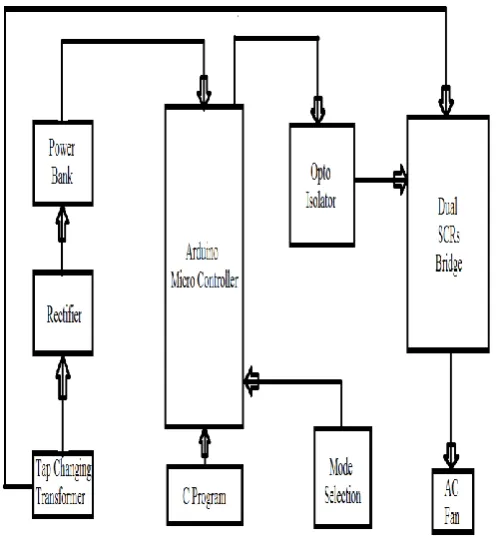
Block Diagram of AC to AC Step down
[image:1.595.107.551.341.777.2]Cycloconverter
Fig 2 shows the block diagram of step down cycloconverter in this the arduino microcontroller to be used.
Fig 2: Block Diagram
Components Used:
1. Tap Changing Transformer 2. Rectifier
3. Arduino Microcontroller 4. Opto Isolator
5. SCRs 6. AC Fan 7. Bulb
[image:1.595.311.560.347.625.2]© 2017, IRJET | Impact Factor value: 5.181 | ISO 9001:2008 Certified Journal | Page 1612
1.2 Working of AC to AC Step down Cycloconverter
[image:2.595.306.559.81.341.2]It consists of two full-wave, fully controlled bridge thyristors, where each bridge has 4 thyristors, and each bridge is connected in opposite direction (back to back) such that both positive and negative voltages can be obtained as shown in figure below. Both these bridges are excited by single phase, 50 Hz AC supply.
Fig 3: Equivalent Circuit
During positive half cycle of the input voltage, positive converter (bridge-1) is turned ON and it supplies the load current. During negative half cycle of the input, negative bridge is turned ON and it supplies load current. Both converters should not conduct together that cause short circuit at the input.
To avoid this, triggering to thyristors of bridge-2 is inhibited during positive half cycle of load current, while triggering is applied to the thyristors of bridge 1 at their gates. During negative half cycle of load current, triggering to positive bridge is inhibited while applying triggering to negative bridge.
By controlling the switching period of thyristors, time periods of both positive and negative half cycles are changed and hence the frequency. This frequency of fundamental output voltage can be easily reduced in steps, i.e., 1/2, 1/3, 1/4 and so on.
The figure 4 shows output waveforms of a cyclo-converter that produces one-fourth of the input frequency. Here, for the first two cycles, the positive converter operates and supplies current to the load.
[image:2.595.40.288.207.427.2]It rectifies the input voltage and produce unidirectional output voltage as we can observe four positive half cycles in the figure. And during next two cycles, the negative converter operates and supplies load current.
Fig 4: Waveform
Here one converter is disabled if another one operates, so there is no circulating current between two converters. Since the discontinuous mode of control scheme is complicated, most cyclo converters are operates on circulating current mode where continuous current is allowed to flow between the converters with a reactor.
This circulating current type cyclo-converter can be operated on with both purely resistive (R) and inductive (R-L) loads.
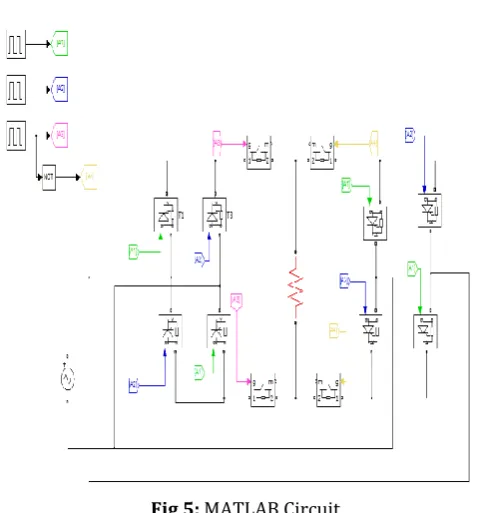
2. MATLAB DESIGN AND RESULTS
Circuit:
[image:2.595.311.551.509.766.2]© 2017, IRJET | Impact Factor value: 5.181 | ISO 9001:2008 Certified Journal | Page 1613 Waveforms:
[image:3.595.37.289.120.332.2]Fig 6: Output at load for normal frequency (f)
Fig 7: Output at load for frequency f=25Hz (f/2)
Fig 8: Output at load for frequency f=16.6Hz (f/3)
3. ARDUINO MICRO CONTROLLER
[image:3.595.313.557.163.391.2]The arduino microcontroller is used in the AC to AC stepdown cycloconverter.
Fig 9: Arduino Micro Controller
As the microcontroller used in this is arduino. A pair of slide switches are provided to select desired speed range F, F/2 and F/3 etc. of operation of induction motor. These switches are interfaced to the microcontroller. The status of switches enables the microcontroller to deliver pulses that trigger a set of SCRs in dual bridge. Thus, the speed control of induction motor can be achieved in three steps i.e. F, F/2 and F/3.
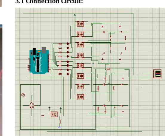
3.1 Connection Circuit:
[image:3.595.52.483.513.754.2] [image:3.595.283.560.521.749.2]
© 2017, IRJET | Impact Factor value: 5.181 | ISO 9001:2008 Certified Journal | Page 1614
3.2 Programing of Arduino Microcontroller for AC
to AC Stepdown Cycloconverter
int moc1 = 2; int moc2 = 3; int moc3 = 4; int moc4 = 5; int moc5 = 6; int moc6 = 7; int moc7 = 8; int moc8 = 9; int button1 = 10; int button2 = 11; int zero = 13; int var1; int var2; void setup() { Serial.begin(9600); pinMode(moc1,OUTPUT); pinMode(moc2,OUTPUT); pinMode(moc3,OUTPUT); pinMode(moc4,OUTPUT); pinMode(moc5,OUTPUT); pinMode(moc6,OUTPUT); pinMode(moc7,OUTPUT); pinMode(moc8,OUTPUT); pinMode(button1,INPUT); pinMode(button2,INPUT); pinMode(zero,INPUT); digitalWrite(zero,HIGH); } void loop() {
var1 = digitalRead(button1); var2 = digitalRead(button2);
if (digitalRead(zero)==LOW) {
if ( var1 == HIGH && var2 == HIGH) { digitalWrite(moc1,HIGH); digitalWrite(moc2,HIGH); digitalWrite(moc3,HIGH); digitalWrite(moc4,HIGH); digitalWrite(moc5,LOW); digitalWrite(moc6,LOW); digitalWrite(moc7,LOW); digitalWrite(moc8,LOW); delay(0.5); digitalWrite(moc1,LOW); digitalWrite(moc2,LOW); digitalWrite(moc3,LOW); digitalWrite(moc4,LOW); delay(19.5); digitalWrite(moc5,HIGH); digitalWrite(moc6,HIGH); digitalWrite(moc7,HIGH); digitalWrite(moc8,HIGH); delay(0.5); digitalWrite(moc5,LOW); digitalWrite(moc6,LOW); digitalWrite(moc7,LOW); digitalWrite(moc8,LOW); delay(19.5); }
else if ( var1 == HIGH && var2 == LOW) { digitalWrite(moc1,HIGH); digitalWrite(moc2,HIGH); digitalWrite(moc3,HIGH); digitalWrite(moc4,HIGH); digitalWrite(moc5,LOW); digitalWrite(moc6,LOW); digitalWrite(moc7,LOW); digitalWrite(moc8,LOW); delay(0.5); digitalWrite(moc1,LOW); digitalWrite(moc2,LOW); digitalWrite(moc3,LOW); digitalWrite(moc4,LOW); delay(29.5); digitalWrite(moc5,HIGH); digitalWrite(moc6,HIGH); digitalWrite(moc7,HIGH); digitalWrite(moc8,HIGH); delay(0.5); digitalWrite(moc5,LOW); digitalWrite(moc6,LOW); digitalWrite(moc7,LOW); digitalWrite(moc8,LOW); delay(29.5); }
© 2017, IRJET | Impact Factor value: 5.181 | ISO 9001:2008 Certified Journal | Page 1615 digitalWrite(moc5,HIGH);
digitalWrite(moc6,HIGH); digitalWrite(moc7,HIGH); digitalWrite(moc8,HIGH); delay(0.5);
digitalWrite(moc5,LOW); digitalWrite(moc6,LOW); digitalWrite(moc7,LOW); digitalWrite(moc8,LOW); delay(29.5);
}
else {
digitalWrite(moc1,LOW); digitalWrite(moc2,LOW); digitalWrite(moc3,LOW); digitalWrite(moc4,LOW); digitalWrite(moc5,LOW); digitalWrite(moc6,LOW); digitalWrite(moc7,LOW); digitalWrite(moc8,LOW);
} } }
3.3 Technical Specifications of Arduino Micro -
Controller
Table of Technical Specifications:
Microcontroller ATmega328P
Operating Voltage 5V
Input Voltage (recommended) 7-12 V
Input Voltage (limit) 6-20 V
Digital I/O Pins 14
Clock Speed 16MHz
PWM Digital I/O Pins 6
Analog Input Pins 6
DC Current per I/O Pins 20mA
DC Current for 3.3V Pin 50mA
SRAM 2KB
EPROM 1KB
Flash Memory 32KB
LED BUILTIN 13
4. CONCLUSIONS
From this work it is observed that speed of an induction motor can be efficiently controlled by using Cycloconverter. The role of Cycloconverter is in speed control of induction motor is to vary the supply frequency which in turn, changes the speed of motor. The speed control of induction motor can be achieved in three steps i.e. (F, F/2 and F/3).
REFERENCES
[1] Vinamra Kumar Govil, Yogesh Chaurasia “Modeling &
Simulation of PWM Controlled Cycloconverter FED Split Phase Induction Motor” International Journal of Advanced Research in Electrical, Electronics and Instrumentation Engineering, Vol. 1, Issue 3, September 2012.
[2] E A Lewis “Cycloconverter Drive Systems” Power
Electronics and Variable Speed Drives, Conference Publication No. 429, IEEE, 1996.
[3] C. Lander, Power Electronics, Second Edition, McGraw Hill, England, 1987
[4] BurakOzpineci, Leon M. Tolbert, “Cycloconverters”,
University of Tennessee-Knoxville, Knoxville, USA.
[5]
J. Zhang, “Single phase input cycloconverters driving an© 2017, IRJET | Impact Factor value: 5.181 | ISO 9001:2008 Certified Journal | Page 1616
BIOGRAPHIES
Viren J. Patel
B.E. in Electrical Engineering at Dr. Subhash Technical campus - Junagadh, Gujarat, India
Dipak K. Makawana
B.E. in Electrical Engineering at Dr. Subhash Technical campus - Junagadh, Gujarat, India
Vishal M. Rangpara
B.E. in Electrical Engineering at Dr. Subhash Technical campus - Junagadh, Gujarat, India
Jaydipsinh B. Zala