© 2018, IRJET | Impact Factor value: 6.171 | ISO 9001:2008 Certified Journal | Page 3592
A COMPARATIVE STUDY ON THE SENSITIVITY OF MAT FOUNDATION
TO SOIL STRUCTURE INTERACTION
Umesh R
1, Divyashree M
21
M.Tech student, Civil Engineering Department, P.E.S College of Engineering – Mandya
2Assistant Professor, Civil Engineering Department, PESCE – Mandya
---***---Abstract -
Influence of stiffness characteristics of thefoundation system on the overall structural behavior of structures has always been an area of interest in the domain of structural engineering. In the present study an attempt is made to assess the sensitivity of the structural behavior of a 100 mT capacity silo resting on a mat foundation to the variation in soil sub grade modulus. For this purpose, Winkler model of linear springs has been used to model the soil structure interaction and the analysis is carried out for different modulus of sub-grade reaction keeping the SBC of soil as 150kN/m2 and considering the allowable settlement as
1mm. 12.5mm, 25mm and 50m. STAAD Pro V8i and STAAD foundation software tools have been used for modeling and analysis of the structure. Internal forces and deflections in the structural members are monitored and compared considering different modulus of sub-grade reaction. The results show a significant influence of sub-grade soil characteristics on the internal forces and displacements in the structural elements.
Key Words
: Soil structure interaction, Sub structure method, Winkler model, Sub-grade of modulus.1. INTRODUCTION
All problems in Civil Engineering involve interaction of structural elements with ground. When forces are applied externally to the structural element, the physics of the problem dictates the structural Element and ground to deform in a compatible manner. This is because of inherent intendancy of structural-element displacements and ground displacements by the virtue of their intimate physical contact. Therefore, these types of problems are broadly referred to as Soil-structure interaction (SSI) problems. In conventional structural design, SSI effects are not considered. Neglecting SSI effect for a relatively flexible structure founded on hard soil is reasonable. But, for a relatively stiff structure founded on either soft or medium soil neglecting SSI has a great impact on structural response and design.
1.1 SOIL – STRUCTURE INTERACTION
If the structure is supported on soft soil deposit, the inability of the foundation to conform to the deformations of the free field motion would cause the motion of the base of the structure to deviate from the free field motion. Also the dynamic response of the structure itself would induce deformation of the supporting soil. This process, in which the response of the soil influences the motion of the
structure and the response of the structure influences the motion of the soil, is referred as SSI. The first significant structure where the dynamic effect of soil was considered in the analysis in industry in India was the 500MW turbine foundation for Singrauli (Chowdhary, 2009).
1.2 Winkler model
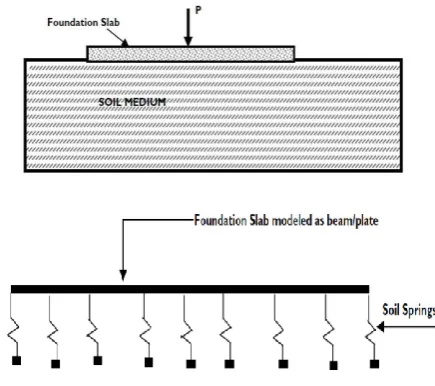
Winkler first studied the beam on elastic springs. The model he developed is known as Winkler foundation model. This model is the oldest and simplest elastic foundation model. The beam in Winkler foundation model is based on the pure bending beam theory commonly used in structural analysis. In this model it is assumed that the displacement at any point on the surface of the foundation is directly, proportional to the foundation surface pressure, acting at that point and is independent of pressure applied at other locations. In this method, the vertical translations of the soil ‘w’, at a point is assumed to depend only upon the contact pressure ‘p’, acting at the point in the idealized elastic foundation and a proportionality constant, K.
p = K w……….. (1)
The proportionality constant, K, is commonly called the modulus of sub grade reaction. The model was first used to analyze the deflections and resultant stresses in railroad tracks. In the intervening years, it has been applied to many different soil-structure interaction problems.
[image:1.595.332.550.542.735.2]© 2018, IRJET | Impact Factor value: 6.171 | ISO 9001:2008 Certified Journal | Page 3593 a. Winkler’s idealization represents the soil medium
as a system of identical but mutually independent, closely spaced, discrete, linearly elastic springs
b. According to this idealization, deformation of foundation due to applied load is confined to loaded regions only.
c. Figure shows the physical representation of the Winkler foundation.
d. The pressure–deflection relation at any point is given by p= K w, where K = modulus of sub grade reaction.
1.3 MODULUS OF SUB GRADE REACTION
The modulus of sub-grade reaction is a relationship between soil pressure and deflection that is widely used in structural analysis of foundation members. It is used for continuous footings, mats and various types of piling. The modulus of sub-grade reaction is calculated from plate load test using following equation
K = q/δ………. (2)
Here, K = modulus of sub-grade reaction (kN/m3), soil spring
q = mean bearing pressure
δ = mean settlement
Fig - 2:Mat foundation rest on soil spring support
1.4 MODELING OF MAT FOUNDATION BY WINKLER APPROACH
Modeling of RC MAT foundation describes the structural behavior of different soil modulus of sub grade and change in foundation depth. Mat selected for analysis is symmetrical in plan of 4.5 x 4.5m with centre to centre column spacing is 2.26 m. Different modulus of sub grade is introduced keeping same SBC with varying settlement criteria and also varying in depth for that soil stiffness in order to know internal force of mat foundation the displacement and moment. The soil under the raft slab is represented by a set of springs for which the spring constants k, adjusted to reflect the corresponding soil type.
1.5 Mat size used for the foundation structures are as follows
The columns of the frame are founded on raft slab. The raft slab is divided into finite number of plates with plan dimension of 100mm×100mm and having thickness of 300 mm for analysis purpose.
The raft slab is projected 1.12 m from the centre of columns on all four sides of the structure.
The supporting soil with modulus of sub grade reaction is 150000, 12000, 6000, 3000 for SBC 150 kN/m3, for the deflection of 1 mm, 12.5 mm, 25 mm, 50 mm respectively.
For the same settlement and sub grade modulus the foundation depth is 300mm, 400mm, 500 mm varied for study.
[image:2.595.393.492.394.493.2] For analysis purpose STAAD Pro and STAAD foundation is used and vertical and lateral load combination effect of sub grade on structure and varying depth of foundation on soil interaction is studied. In this study we have taken forces in vertical and lateral along x direction for the same we have carried out analysis.
Fig - 2:Typical 3D modeling of mat foundation
1.6 METHOD OF ANALYSIS
[image:2.595.55.232.417.569.2]© 2018, IRJET | Impact Factor value: 6.171 | ISO 9001:2008 Certified Journal | Page 3594 Table 1:
Loading details
LOAD DETAILS : ACTION FORCE (kN)
CEMENT SILO 100T Ø 3.2m
C1 C2 C3 C4
VZ VZ HX VZ VZ HX
Dead load 30 30 30 30
Use full load 338 338 338 338
Wind in
X-Direction +59.5 -59.5 +15.4 59.5 -59.5 +15.4
2. RESULT
In the present study mat foundation maximum and minimum displacement, moment in both direction are considered to evaluate the Performance of under different soil modulus of sub grade and variation in thickness of mat parameters under the vertical and lateral loading condition. This analysis was carried out under sub structure method consider soil as in elastic condition.
a) Table 2 shows that the maximum displacement below the mat footing increases as the modulus of sub grade decreases.
b) Table 3 shows that the minimum displacement below the mat footing increases as the modulus of sub grade decreases.
c) From the graph 1 and 2 it is observed that initial settlement causes major changes in the moment in both ‘x’ and ‘y’ directions.
d) From the graph 3 and 4, it is observed that the displacement below mat footing is directly proportion to the stiffness of the soil. Hence, when the stiffness of the soil is higher; the displacement below footing is lower and vice- versa.
[image:3.595.32.292.98.195.2]e) Form the graph 5 to 8 and tables 4 & 5; it is observed that as the depth of foundation mat increases, there is a variation in the bending moment. As seen from the table 4, for 300mm depth of mat; moment in X-axis is 6.08%, 0.56% and 0.31%. Accordingly, it is also observed that the bending moment decreases as the depth of the mat increases; with respect to the modulus of sub-grade in both ‘x’ axis and ‘y’ axis.
Table 2: Maximum displacement corresponding soil stiffness
SBC 150 (kN/m²) Allowable
settlement (mm)
Modulus of sub grade (kN/m³)
Max displacement (mm)
12.5 12000 8.849
25 6000 18.027
50 3000 36.402
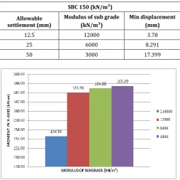
Table 3: Minimum displacement corresponding soil stiffness
SBC 150 (kN/m²)
Allowable settlement (mm)
Modulus of sub grade (kN/m³)
Min displacement (mm)
12.5 12000 3.78
25 6000 8.291
50 3000 17.399
Graph 1: Bending moment variation with respect to modulus of sub-grade in X-axis with constant mat thickness
Graph 2: Bending moment variation with respect to modulus of sub-grade in Y-axis with constant mat thickness
[image:3.595.308.559.392.539.2]© 2018, IRJET | Impact Factor value: 6.171 | ISO 9001:2008 Certified Journal | Page 3595 Graph 4: Minimum displacement for varying mat depth to
[image:4.595.279.558.46.227.2]soil stiffness
Table 4: Percentage of bending moment variation along X axis SBC 150 (kN/m²)
Allowable settlement (mm)
Moment in X-axis 300
(mm) Moment in X-axis 400 (mm) Moment in X-axis 500 (mm)
12.5 to 25 0.56 0.27 0.14
[image:4.595.35.291.431.723.2]25 to 50 0.31 0.14 0.07
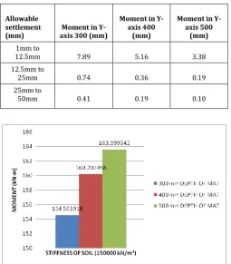
Table 5: Percentage of bending moment variation along X axis SBC 150 (kN/m²)
Allowable settlement
(mm) axis 300 (mm) Moment in
Moment in Y-axis 400
(mm)
Moment in Y-axis 500
(mm) 1mm to
12.5mm 7.89 5.16 3.38
12.5mm to
25mm 0.74 0.36 0.19
25mm to
50mm 0.41 0.19 0.10
Graph 5: Maximum bending moment for varying mat depth having soil stiffness as 150000 KN/m 3
Graph 6: Maximum bending moment for varying mat depth having soil stiffness as 12000 KN/m3
Graph 7: Maximum bending moment for varying mat depth having soil stiffness as 6000 KN/m3
Graph 8: Maximum bending moment for varying mat depth having soil stiffness as 3000 KN/m3
3. CONCLUSION
© 2018, IRJET | Impact Factor value: 6.171 | ISO 9001:2008 Certified Journal | Page 3596
REFERENCES
1. Winkler (1867) proposed a foundation model consisting of closely spaced independent linear springs. These models are used to consider the flexibility of soil in the analysis of structures
2. George Gazetas, Member, ASCE, “Formulas and charts for impedances of surface and embedded foundations.”
3. Bowles, J.E.(1998).”Foundation Analysis and design”, McGraw Hills, New York
4. Sekhar Chandra Dutta, Rana Roy, “A critical review on idealization and modeling for interaction among soil-foundation structure system”, Computers and Structures 80 (2002), pp.1579_1594. Vivek Garg, M.S. Hora, "A review on interaction behavior of structure-foundation-soilsystem.”, International Journal of Engineering Research and Applications, Vol. 2, Issue 6, November- December 2012, pp.639-644.
5. "Soil Structure Interaction The Early Stages" Journal of Applied Science and Engineering, Vol. 16, No. 1, pp. 1_8 (2013).
6. "Parametric study of R.C frames with raft foundation considering soil structure interaction using spring international" journal of scientific development and research april 2016 ijsdr | volume 1, issue 4.