© 2017, IRJET | Impact Factor value: 5.181 | ISO 9001:2008 Certified Journal | Page 266
Assessment & Optimization of Influence of some Process Parameters
on Sheet Metal Blanking
Vikrant J. Jadhav
1, Mr. B.R. Shah
21
ME - Mechanical Engineering (Computer Aided Design, Manufacture & Engineering)
2M.E- Mechanical Engineering Design
---***---Abstract -
Metal blanking is a widely used process in highvolume production of sheet metal components. Blanking consists of a metal forming operation characterized by complete material separation. Low carbon steel is a very common material used in fabrication of sheet metal components. The experimental studies were conducted under varying sheet thickness, clearance and wear radius and shear angle. The main objectives are to present the development of a model to predict the shape of the cut side. The model investigates the effect of potential parameters influencing the blanking process their interactions. This helped in choosing the process leading parameters for two identical product manufactures from two different materials blanked with reasonable quality on the same Tool/Die.
Optimization is one of the techniques used in manufacturing sector to arrive for the best manufacturing condition. This is an essential need of industries towards manufacturing of quality product at lower cost. The main objective of this study is to treasure optimal parameters such as sheet thickness, clearance and wear radius in blanking to find out the variations in three performance characteristic such as burr height, accuracy and circularity value for blanking of medium carbon steel. Based on experiments are conducted on L-9 orthogonal array, analysis has been carried on by using Grey Relational Analysis, a Taguchi method. Response tables and graphs were used to find optimal level of parameters in blanking process. The obtained results shows that the Taguchi Grey Relational Analysis is being effective technique to optimize the parameters for blanking process
Key Words: Blanking, GRA, GRG, Taguchi method, Orthogonal
Array, Finite ElementAnalysis (FEA)
1. INTRODUCTION
Die design is a large division of tool engineering, is complex, fascinating subject. It is one of the most existing of all the area of tool design. Stamping presses and stamping dies are tools used to produce high volume sheet metal parts. These parts achieve their shapes through the effect of the die. Sheet metal stampings have now replaced many components, which were cast or machined. material economy and the resultant reduction in weight and cost, high productivity, use of unskilled labor, and a high degree of possible precision
have rendered press work indispensable for many mass produced goods.
For the manufacturing of the die, the selection of appropriate material selection of manufacturing process and highly precise mating of the upper and lower half of the die is significant. The proper heat treatment of die blocks, and prevents warping. Also, manufacturing within the tolerances limits provided is important for proper functioning of the die and obtaining dimensional accuracy in the product. Also while designing and manufacturing of die the factor of economy is also kept in mind. Press working may be defined as a chip less manufacturing process by which various components are made from sheet metal. The machine used for press working is called a press. The main features of a press are: a frame which supports a ram or a slide and a bed, a source of mechanism for operating the ram in line with and normal to the bed. The ram is equipped with a suitable punch and a die block is attached to the bed. A stamping is produced by downward stroke of ram when the punch moves towards and into the die block.
1.1 Components of the Die and the Press
A simple cutting die used for punching and blanking operation is shown in fig. Below the definition of main components of the press are given.
Bed
The bed is the lower part of press frames that serves as a table to which bolster plate mounted.
Bolster plate
This is a thick plate secured to the press bed, which is used for locating and supporting the die assembly. It is usually 5 to 12.5 mm thick.
Die-set
© 2017, IRJET | Impact Factor value: 5.181 | ISO 9001:2008 Certified Journal | Page 267
Die
The die may be defined as a female portion to complete tool for producing work in a press. It is also referred to a complete tool consisting of a pair of members for producing work in a press.
Lower shoe
The lower shoe of die set is generally mounted on the bolster plate of the press. The die block is mounted on the lower; also the guide post is mounted in it.
Punch
This is the male components of the assemblies, which is directly or indirectly moved by and fastens to the press ram or slide.
Punch plate
The punch plate or the punch plate retainer fits closely over the body of the punch and holds in proper relative position.
Upper shoe
This is the upper part of the die, which contains guidepost bushing and guidepost assembly.
Back up plate
Back up plate or pressure plate is placed so that the intensity of pressure does not become excessive on punch holder. The plate distributes the pressure over a wide area and the intensity of pressure on the punch holder is reduced to avoid crushing.
Stripper
It is the plate which used to strip the metal strip from a cutting punch or die it may also guide the strip.
Knock-out
It is mechanism usually connected to and operated by the press ram for pressing a work piece from die.
1.2 Press Working Operations
The sheet metal operations done on a press may be grouped into two categories, cutting operations and forming operations. In cutting operations, the work piece is stressed beyond its ultimate strength. The stresses caused in the metal by the applied forces will be shearing stresses. In forming operations, the stresses are below the ultimate strength of the metal. In this operation, there is no cutting of the metal but only the contour of the work piece is changed
to get the desired product. The cutting operations include: blanking, punching, notching, perforating, trimming, shaving, slitting and lancing etc. the forming operations include: bending, drawing, redrawing and squeezing. The stresses induced in the metal during bending and drawing operations are tensile and compressive and during the squeezing operations these are compressive
1.3 Working of Cutting Dies
As it is clear in the figure, the punch holder (upper shoe) is fastened directly to the ram of the punch press, and the die shoe (lower shoe) is fastened to the bolster plate of the press. Guide posts may be used to better align the punch holder with the die shoe. These main components (Punch holder, Die shoe and Guide Posts) constitute what is known as the die set. A die set can be had with two guide posts located at the rear of the die set (Known as back post), diagonally, one at the die set. The lower ends of the guide posts are press fitted into the die shoe. At the upper end, the guide posts have a slip fit with the guide bushings. The punch is fastened to the punch holder and the die block is fastened to the die-shoe. The punch is aligned with the opening in the block. Since, both the punch and the die-block act as cutting tools, they are hardened.
Fig.1: Press working operations
© 2017, IRJET | Impact Factor value: 5.181 | ISO 9001:2008 Certified Journal | Page 268
2. Blanking Process
Blanking is a manufacturing operation as old as the technology itself. Its applications range from components of very light to heavy appliances and machineries. Blanking is defined as the cutting of a work piece between two die components to a predetermined contour. During blanking, the part is subjected to complex solicitations such as deformation, hardening and crack initiation and propagation. The theoretical modeling of such processes is very difficult due to the complexity in describing the different stages of the whole shearing process starting with the elastic stage and ending with the total separation of the sheet metal.
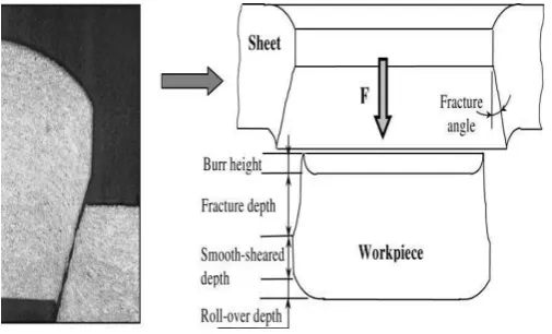
Blanking process, which is also referred to as shearing, or punching process, is illustrated in Fig. . A metal sheet is pressed on a die by a blank holder and perforated by a punch. Four characteristic dimensions can be distinguished on the blanked edge such as the roll over depth, the fracture depth, the smooth sheared depth, the burr formation and fracture angle.
Fig.: Geometry of the sheared work piece.
2.1 Deformation and Rupture Mechanism
During sheet metal shearing operation, the part is subjected to complex solicitations such as deformation, hardening and crack initiation and propagation. The theoretical modeling of such processes is very difficult due to the complexity of describing the different stages of the whole shearing process starting from the elastic stage and ending to the total separation of the sheet metal Fig.6. Accurate knowledge of the failure process is essential for the selection of a suitable damage model. In the case of sheet blanking by shearing processes, numerous authors have studied the different physical mechanisms leading to the final rupture, and proposed their own models.
1. Elastic stage 2. Elastoplastic stage
3. Elastoplastic stage in which damage occurs.
[image:3.595.36.289.362.515.2]4. Initiation propagation of crack leading to final rupture.
Fig.: Different stage of the blanking process
A set of formulae taking into account the material characteristics of the sheet, the geometry of the operation and the wear state of the tool has been developed allowing for the prediction of the characteristic zone heights of the blanked part such the heights of the burr the roll-over, the sheared and the fractured zones. The punch penetration curve can also be plotted which allows for the computation of the maximum blanking force and the blanking energy.
2.1 Main Objective of this Project
The main aim of this study is to evaluate the influence of tool clearance, friction, sheet thickness, punch /die size and blanking layout on the sheet deformation. Hence for optimizing various blanking process parameters following objectives are decided
1. To review the literature on blanking process. 2. To design the die for selected blanking operation. 3. Select various process parameters for in-depth analysis. 4. To optimize selected blanking process parameters. 5. Study actual stress concentration on sheet during blanking. 6. Study of deformation on punch and die using Analysis.
3. EXPERIMENTATION
© 2017, IRJET | Impact Factor value: 5.181 | ISO 9001:2008 Certified Journal | Page 269 Table: Hardware List
Fig.: Video measuring machine (VMM)
3.1 Selection of Blanking Parameters
The methodology that is followed to attain the research objectives is divided into the following work phases:
1) Classify the blanking parameters into controllable and uncountable. The identified controllable parameters are clearance, blank holder force, sheet metal thickness, and material type. While, the uncountable parameters are material properties, inconsistency and conditions (shape, defects and internal stresses), friction and wear state of the tool, stroke rate or blanking speed, and punch-die alignment.
2) Choose the controllable factors that influence the blanking process.
Select an appropriate working range for each potential factor. It is found that the working range of clearance fall within the range (0-15%) of the sheet metal thickness and the working range of the thickness of the used material fall within the range (0.3-0.5) mm.
3) Prepare to use of Design of Experiments (DOE) technique by selecting the experimental levels for each selected factor, i.e. the clearance to be in three levels (5, 10, 15 %) of the sheet metal thickness i.e.0.3, 0.4, 0.5 mm.
Fig.: Blanking process parameters
A) Influence of Blanking Clearance
Dm, Dp, and t are, respectively, the die diameter, the punch diameter, and the sheet thickness.
In order to study the influence of this design parameter, three tools have been designed corresponding to four different clearances, 5%, 10%, a n d 15%. These values correspond to the most used clearances in industry.
B) Influence of the sheet thickness
For a given material, the energy requirement in blanking is influenced by the sheet thickness. It has been observed that:
1. The blanking energy decreases with increasing clearance to sheet thickness ratio c/t and increases with increasing sheet thickness.
2. The proportions of the different depth characteristics of the sheared profile are affected by the thickness.
3. To study the effects of the interactions between the clearances and the sheet thickness, a series of experiments have been carried out with four thickness values of sheet i . e 0.30, 0.40, and 0.50.
C) Influence of the tool wear / wear radius
The design of the tool is one of the main features in the industrial process. Therefore it is necessary to study the effects of tool wear on the blanking force and the sheared profile variations. The quality of the work piece is governed by the state of the tool wear.
© 2017, IRJET | Impact Factor value: 5.181 | ISO 9001:2008 Certified Journal | Page 270 Three wear states of the tool were chosen corresponding to:
A new die with: Rwd= 0.01 mm. A new punch with: Rwp= 0.01 mm.
Two “worn out” punches with different edge radii Rwp= {0.15, 0.3} mm.
4. GREY RELATIONAL ANALYSIS
In a blanking operation, many factors simultaneously influence on blanking process to determine the state of development of the system Usually, we want to know which factors influences the system more and which factor influences the system little. However, the relationship between various factors is usually grey where the information is unclear, incomplete and uncertain. Moreover, practical and experimental data was difficult to obtain and too much scatter to analyze. Two conventional statistical methods frequently used on the relationship between independent and dependent factors were factor analysis and regression analysis methods. Comparing to regression analysis and factor analysis in mathematic statistics, grey relational has some merits such as small sample, having no use for typical distribution, no requirement for independency and small amount of calculation. Additionally, GRA analysis is already proved to be simple and accurate method for selecting factors especially for those problems with unique characteristic. Grey relational grade (GRG) can be used to describe the relationships among the factors and to determine the important factors that significantly influence some defined objectives. GRA can provide a ranking scheme that rank the order of the grey relationship among dependent and independent factors and this allow us to decide which input factors need to be considered more precisely. In the case when experiments are ambiguous or when the experimental method cannot be carried out exactly, grey analysis helps to compensate for the shortcoming in statistical regression .Grey relation analysis is an effective means of analyzing the relationship between sequences with less data and can analyze many factors that can overcome the disadvantages of statistical method. Taguchi method or Taguchi approach is a DOE technique with new experimental strategy where the quality is defined in general terms. The method could be used not only to improve quality, but also to quantify the improvements made in terms of saving money. The experimental design and analyze of the results can be done with less effort and expenses by using the Taguchi approach. Since the method enormously reduces the number of experiments.
4.1 Flowchart of the Taguchi method
The first step of Taguchi method requires the knowledge about the domain that is examined, since the main function, side effects and failure modes have to be identified. A wrong decision in this step makes all other steps useless. The second step is to find control factors and their levels. To
reduce the number of experiments, only the most important factors should be considered
Two or three factor levels can be chosen. In the latter case, the levels should be evenly distributed. The factor levels should be placed very carefully, since the Taguchi method defines the significant and optimal parameters only within the levels. The orthogonal array that defines the experiments is selected in the third step. The fourth step is to perform the experiments. Optimal factors are predicted in the fifth step. And in the last step of Taguchi method optimal parameters should be tested to confirm or reject optimal parameters found by Taguchi method.
4.2 GREY RELATIONAL ANALYSIS
In Grey relational analysis, experimental data i.e., measured features of quality characteristics are first normalized ranking from zero to one. This process is known as Grey relational generation. Next, based on normalized experimental data, Grey relational coefficient is calculated to represent the correlation between the desired and actual experimental data. Then overall Grey relational grade is determined by averaging the Grey relational coefficient corresponding to selected responses. The overall performance characteristic of the multiple response process depends on the calculated Grey relational grade.
4.3 Process Parameters
© 2017, IRJET | Impact Factor value: 5.181 | ISO 9001:2008 Certified Journal | Page 271 In this work, L-9 Orthogonal Array design matrix is used to
set the control parameters to evaluate the process performance. The next table shows the design matrix used in Experimentation.
Experiments were conducted as per L-9 orthogonal array, assigning various values of the levels to the process parameters. After individual experiments for each set of values were conducted on medium carbon steel sheet for Ø10mm Blank, burr height, Accuracy and Circularity are calculated using video measuring machine (VMM) and the final results.
Following Table and fig shows experimental results and individual effect of process variables on burr height.
Assembly Model – A
Sheet / strip thickness 0.30mm, Blanking punch diameter 9.97mm (with the clearance 5 % of sheet thickness) In all loading conditions, the maximum deformation on sheet. at the region where actual force is applied and on die plate contact area of punch and die with sheet / strip.
4.4
Conformation of Results
The Confirmation for the optimal process parameters with its level has conduct to evaluate quality characteristics for Blanking of medium carbon steel sheet. Table 14 shows highest grey relational grade, indicating the initial process parameters set of A1B1C1 for the best multiple performance characteristics among the nine experiments. Table 14 shows the comparison of the experimental results for the conditions (A1B1C1) with predicted result for optimal (A1B1C1) Blanking process parameters.
Predicted Response=Average of A1 + Average of B1 + Average of C1 – 2 x Mean of response (Yij)
The response value obtained from the experiment are Minimum Burr height = 0.039 mm, Accuracy of Blank = 10.012 mm, and Circularity of Blank = 10.008mm. The comparison is shows the good agreement between the predicted and experimental values.
4.5 FINITE ELEMENT ANALYSIS [FEA]
FEA consists of a computer model of a material or design that is stressed and analyzed for specific results. It is used in new product design, and existing product refinement. A company is able to verify a proposed design will be able to perform to the client's specifications prior to manufacturing or construction. Modifying an existing product or structure is utilized to qualify the product or structure for a new service condition. In case of structural failure, FEA may be used to help determine the design modifications to meet the new condition.
Methodology of work
© 2017, IRJET | Impact Factor value: 5.181 | ISO 9001:2008 Certified Journal | Page 272 Step-II: With the help of Literature survey and Technical
Knowledge Preparing CAD Model Blanking tool (Punch and Die)
Step-III: With the help of 3-D Model from CAD System Preparing Meshed 3-D Model for Analysis
Step-IV: Extracting Results from CAE Software
5 CONCLUSIONS
The developed experimental investigation of the sheet metal blanking process makes it possible to study the effects of process parameters such as the material type, the punch-die clearance, the thickness of the sheet and the blank holder force and their interactions on the geometry of the sheared edge especially the burrs height .In general, clearance plays a key role in both product quality and the service life of dies. A good clearance design not only increases the quality of product manufactured, but also reduces product’s burr. As a result, the wear of punches and dies can be greatly reduced and the life expectancy of punching dies increased. More punching times is positively related to bigger wear, while less punching times is related to smaller wear.
The numerical FEA simulation shows the deformation during shearing on punch ranging from 0.074mm to 0.139mm, die 0.000051µ to 0.017µ. These values increase for greater frictional coefficient. The blanking process can be considered as cold working process due to the maximum temperature of 365 K (92˚ C) Attained in the sheet shear region.
ACKNOWLEDGEMENT
I wish to express my profound gratitude to the almighty god for guiding us to successfully complete this work. I take this opportunity to express my deep sense of gratitude to my guide, Prof B.R. Shah for his continuous guidance and encouragement throughout the course of this study. Without his valuable suggestion and encouragement this would not have been possible. It is because of his experience and wonderful knowledge; I could fulfill the requirement of completing the Project report II within the stipulated time.
I would also like to thank Dr.Atul Padalkar, Principal, Flora Institute of Technology, Khopi, Pune for their through valuable support.
I acknowledge with thanks, the assistance provided by the departmental staff and library staff. I thank all my colleagues for their valuable cooperation and coordination which was available from time to time.
REFERENCES
[1]R. Hambli, “Design of Experiment Based Analysis for Sheet Metal Blanking Processes Optimization”,Journal of material processing Technology 28-33.
[2]F. Faura, A. Garcia, M. Estrems, “Finite element analysis of optimum clearance in the blanking process” Journal of material processing Technology 80-81 (1998)
[3]R. Hambli, S. Richir, P. Crubleau, B. Taravel, “Prediction of optimum clearance in sheet metal blanking processes”
[4]Emad Al-Momani, Ibrahim Rawabdeh,“An Application of Finite Element Method and Design of Experiments in the Optimization of Sheet Metal Blanking Process” Jorden Journal of Mechanical and Industrial Engineering, Volume 2 Number 1, March 2008, ISSN 1995-6665, Pages 53-63.
[5] S. K. Maiti, A. A. Ambekar, U. P. Singh, P.P. Date, K. Narasimhan, “Assessment of influence of some process parameters on sheet metal blanking”.Journal of Materials Processing Technology. Journal of Material Processing and Technology 102 (2000) 249-256.
[6]RidhaHambli, “BLANKSOFT: a code for sheet metal blanking processes optimization”Jorden Journal of Mechanical and Industrial Engineering, Volume 2 Number 1, March 2008, ISSN 1995-6665, Pages 21-26.
[7]RidhaHambli,“Optimization of blanking process using neural network simulation” Trans Nonferrous Met. Sco. China.Vol 13, No2, April-2003
[8]Wunhua St., Huwei, Yunlin,Taiwan“The optimal clearance design of micro-punching die” Journal of material processing Technology 80-81 (1998) 111-115
[9]PENG JiaGeng,LIShouben, “Numerical and optimization of clearance in sheet shearing process”. Journal of Material Processing and Technology, ELESVIER, 122 (2002) 249-254. [10]Emad Al-Momani, Ibrahim Rawabdeh, “An Application of Finite Element Method and Optimization of Sheet Metal Blanking Process”.
[11]Avinash S. Sangwikar1 and S. B. Chandgude“Process Parameter Optimization during Blanking of Low Carbon Steel using Taguchi Method”.
[12]R. S. Mohan Kumar, BalaMurugan .C.M “Development of alternate knowledge based system for optimization of blanking die design parameters selection”.
[13]D. Brokken, W.A.M. Brekelmans, F.P.T. Baaijens, “Predicting the shape of blanked products: finite element approach”.Journal of Material Processing of Technology 103 (2000) 51-56.
[14]D. Brokken, W.A.M. Brekelmans, F.P.T. Baaijens, “Predicting the shape of blanked products: finite element approach”.